


REFRIGERATOR SERVICE MANUAL
CAUTION
BEFORE SERVICING THE UNIT,
 READ THE SAFETY PRECAUTIONS IN THIS MANUAL.
 Model #s:
P/No. MFL62188020
795.71052.01, 795.71053.01, 795.71054.01
- SPECIFICATIONS 3-4
- PARTS IDENTIFICATION 5
-
REMOVING AND REPLACING REFRIGERATOR DOORS 6
DOOR 7
DOOR ALIGNMENT 8
FAN AND FAN MOTOR (EVAPORATOR) 8
DEFROST CONTROL ASSEMBLY 8
LAMP 9
MULTI DUCT 9
DISPENSER 10
DISPLAY PWB REPLACEMENT 10
FUNNEL REPLACEMENT 10
SUB PWB FOR DISPENSER 10
CAP DUCT REPLACEMENT 11
CAP DUCT MOTOR REPLACEMENT 11
ICE CORNER DOOR REPLACEMENT 11
ICE MAKER REPLACEMENT 12
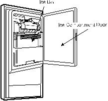
HOW TO REMOVE A ICE BIN 13
HOW TO INSERT A ICE BIN 13
HOW TO REMOVE AND REINSTALL THE PULLOUT DRAWER 14-15
WATER VALVE DISASSEMBLY METHOD 16
FAN AND FAN MOTOR DISASSEMBLY METHOD 16
PULL OUT DRAWER 17
-
ADJUSTMENT 18-19
INTRODUCTION OF E-LINEAR COMPRESSOR 18-20
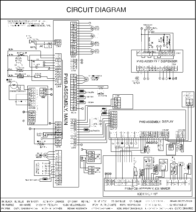
- CIRCUIT DIAGRAM 21
- TROUBLESHOOTINTG 22
- PCB PICTURE 23-24
- TROUBLESHOOTING WITH ERROR DISPLAY 25-34
- TROUBLESHOOTING WITH ERROR DISPLAY 35-44
- REFERENCE 44-49
- COMPONENT TESTING INFORMATION 50-54
- TRBOUBLESHOOTING 55-61
- ICEMAKER OPERATING METHOD AND TROUBLE SHOOTING 62-65
- DESCIPTION OF FUNCTION & CIRCUIT OF MICOM 66-69
SAFETY PRECAUTIONS
Please read the following instructions before servicing your refrigerator.
- Unplug the power before handling any electrical components.
- Check the rated current, voltage, and capacity.
- Take caution not to get water near any electrical components.
- Use exact replacement parts.
- Remove any objects from the top prior to tilting the product.
1-1 DISCONNECT POWER CORD BEFORE SERVICING
IMPORTANT – RECONNECT ALL GROUNDING DEVICES
All parts of this appliance capable of conducting electrical
1-7 REPLACEMENT PARTS
28cu,ft 795.71052.01*
795.71053.01*
795.71054.01*
795.71056.01*
795.71059.01*
current are grounded. If grounding wires, screws, straps, clips, nuts or washers used to complete a path to ground are removed for service, they must be returned to their original position and properly fastened.
-
IMPORTANT NOTICE
This information is intended for use by individuals possessing adequate backgrounds of electrical, electronic and mechanical experience. Any attempt to repair a major appliance may result in personal injury and property damage. The manufacturer or seller cannot be responsible for the interpretation of this information, nor can it assume any liability in connection with its use.
-
ELECTRICAL SPECIFICATIONS
Temperature Control (Freezer Compartment) . -6°F to +8°F Defrost Control ……Total Comp Running Time: 7 hrs~50 hrs Defrost Thermostat ……………………………………………… 46°F Electrical Rating : 115VAC, 60Hz ………………………….. 5.2 A
Maximum Current Leakage ……………………………….. 0.5 mA
Maximum Ground Path Resistance ………………. 0.14 Ohms
Energy Consumption …………………… 28cu,ft. 528 (E/STAR)
Defrost Thermostat ………………………………… 6615JB2005H
Defrost Heater ……………………………………….. 5300JK1005D
Evaporator Fan Motor …………………………….. 4681JB1027C
Capacitor (Running) ………………………………. EAE58905701
Compressor (Hi-Side) …………………………….. TCA34649901
Evaporator (Lo-Side) ……………………………….. 5421JJ1003L
Condenser …………………………………………… ACG72915205
Dryer ……………………………………………………. 5851JA2007E Condenser Fan Motor ……………………………. .4681JB1029D
Temperature Control …………………….. ACQ76217902(STS)
ACQ76217904(WB) ACQ76217906(SW) ACQ76217907(TI) ACQ76217908(BI)
Main Control …………………………………………. EBR65002702
Ice Fan Motor ………………………………………… 4681JB1027E
(4681JB1029E) Refrigerator Fan Motor ………………………………4681JB1027J
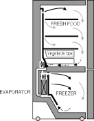
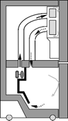
1-8 AIR FLOW / CIRCULATION D’AIR
- NO LOAD PERFORMANCE CONTROL POSITION: MID/MID
And Ambient of : ……………. 70°F …………………………… 90°F Fresh Food, °F ……………… 33°F to 41°F …….. 33°F to 41°F
Frozen Food, °F ……………. -4°F to +4°F ……… -4°F to +4°F
Percent Running Time …… 35%-45% …………….. 50°F-70°F
EVAPORTOR FAN MOTOR
CONDENSER FAN MOTOR
-
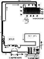
REFRIGERATION SYSTEM
 Minimum Compressor Capacity Vacuum ……………. 21 MIN. Minimum Equalized Pressure
 @ 70°F …………………………………………………… 49 PSIG
@ 90°F …………………………………………………… 56 PSIG
Refrigerant R134a …………………………………………… 4.93 oz.
Compressor ………………………………………………. 956 BTU/hr

INSTALLATION
Clearance must be provided at rear of the refrigerator for air circulation.
AT REAR ……………………………………………………………… 1 in
 ICE ROOM

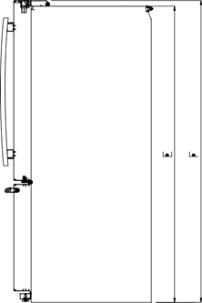
| Description |
795.7105* |
|
| Depth w/ Handles |
A |
35 3/8 in |
| Depth w/ Handles |
B |
32 7/8 in |
| Depth w/ o Door |
C |
29 in |
| Depth (Total with Door Open) |
D |
47 5/8 in |
| Height to Top of Case |
E |
68 3/8 in |
| Height to Top of Door Hinge |
F |
69 3/4 in |
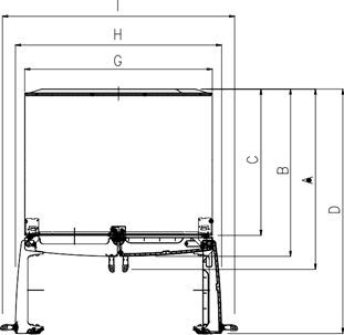
| Width |
G |
35 3/4 in |
| Width (door open 90 deg. w/o handle) |
H |
39 1/4 in |
| Width (door open 90 deg. w/ handle) |
I |
44 1/4 in |
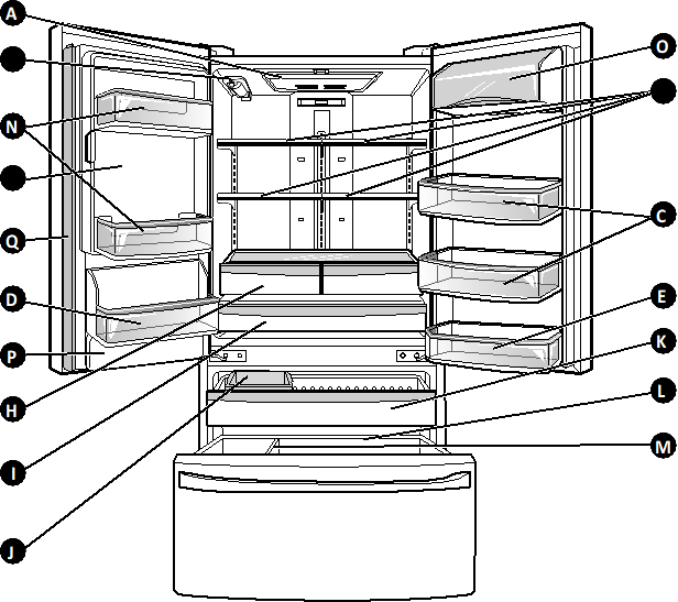


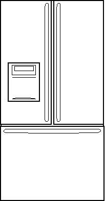
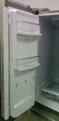
A Refrigerator Light B Filter (Inside)

 C Modular Door Bins D Fixed Door Bin
 Fixed Door Bin
-

 Refrigerator Shelves G Ice Room
(Ice Maker and Ice Bin)

 H Humidity Controlled Crisper I Temperature Controlled
Pantry Drawer
 Extra Ice Bin
K Pullout Drawer L Durabase


 Divider
-

 Door Bins O Dairy Bin

 P Water Tank Cover Q Mullion
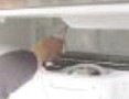
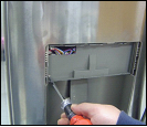
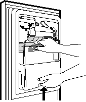
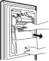
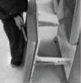
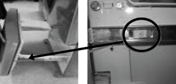
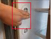
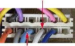
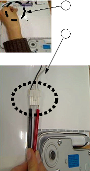
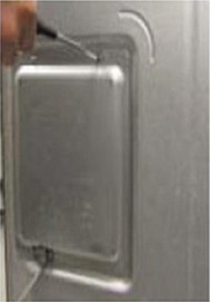
- REMOVING AND REPLACING REFRIGERATOR DOORS
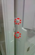
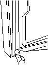
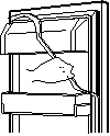
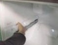
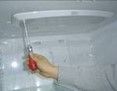
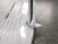
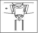
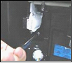
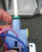
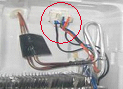
To remove the left refrigerator door:
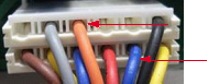
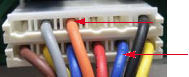
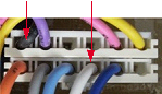
Pull the water tube out of the fitting while pressing the release ring on the fitting.
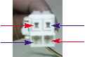
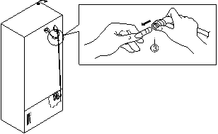 When you pull out the tube, first you have to push the collet by opposite direction of arrow in the upper picture and tube pull out by direction of arrow.
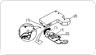
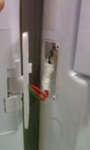
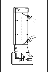
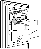
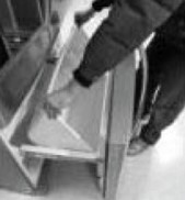
To remove the Right refrigerator door:
 CAUTION: Before you begin, remove food and bins from the doors.

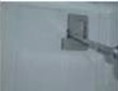
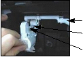
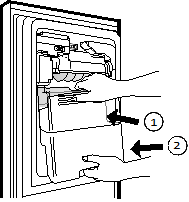
Open the door. Remove the top hinge cover screw (1).

 Lift up the cover (2). Remove the cover.
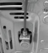
Rotate the hinge lever (3) clockwise.
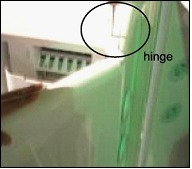
Lift the top hinge (4) free of the hinge lever latch (5). IMPORTANT: When lifting the hinge free of the latch, be careful that the door does not fall forward.


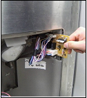
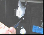
 Open the door. Remove the top hinge cover screw (1). Use a flat-head screwdriver to pry back the hooks (not shown) on the front underside of the cover (2).
 Lift up the cover.
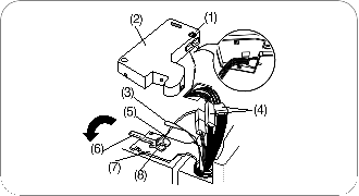
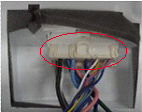
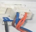
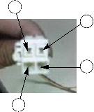
Remove the cover. Pull out the tube (3). Disconnect all the wire harnesses (4). Remove the grounding screw(5)
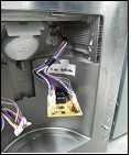
Rotate hinge lever (6) counterclockwise.
Lift the top hinge (7) free of the hinge lever latch (8).
IMPORTANT: When lifting the hinge free of the latch, be careful that the door does not fall forward.

Lift the door from the middle hinge pin and remove the
door.

Place the door, inside facing up, on a nonscratching surface.
-
DOOR

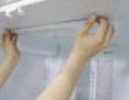
Mullion Removal
- Remove 2 screws.
- Lift mullion up carefully.
- Disconnect wire harness.
 Door Gasket Removal
1. Remove gasket
Pull gasket free from gasket channel on the four remaining sides of door.
Door Gasket Replacement
 1. Insert gasket into channel
Press gasket into channels on the four remaining sides of door.

Mullion Replacement
- Connect wire harness.
-
Insert mullion into channel.
Inserting mullion assy’ into bracket, door
-
Assemble 2 screws.

- Door Alignment
If the space between your doors is uneven, follow the instructions below to align the doors:
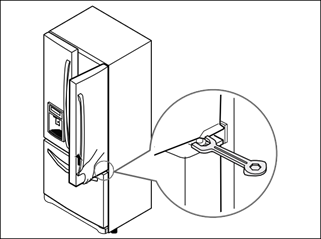 Remove the Base Grillie. Turn the leveling legs (CCW) to raise or (CW) to lower the height of the front of the refrigerator by using flat blade screw driver or 11/32″ wrench. Use the wrench (Included with the User Manual) to adjust the bolt in the door hinge to adjust the height. (CCW to raise or CW to lower the height.)
-
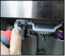
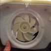
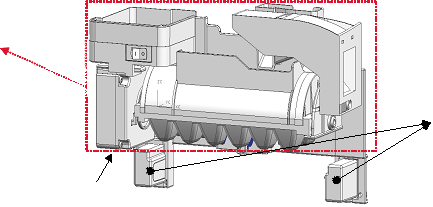
FAN AND FAN MOTOR(EVAPORATOR)
- Remove the freezer drawer. (If your refrigerator has an icemaker, remove the icemaker first)
- Remove the plastic guide for slides on left side by unscrewing phillips head screws.
- Remove the grille by removing four screws and pulling the grille forward.
- Remove the Fan Motor assembly by loosening 3 screws and disassembling the shroud.
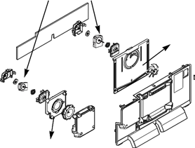 Pull out the fan and separate the Fan Motor and Bracket.

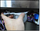
- Ice Fan Scroll Assembly Replacement
- Remove the plastic guide for slides on left side by unscrewing phillips head screws.
- Pull out the cover sensor to disassemble using tools shown in the figure.
- Pull out the cover grille to disassemble using tools shown in the figure.
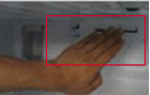
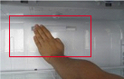
- Put your hand into the inside of grille to disassemble shown in the figure.
- Disconnect wire harness of the grille
- Remove the scroll assembly by loosening all screws
(1) (2)
(3) (4)
(5) (6)
-
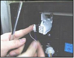
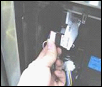
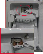
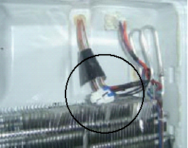
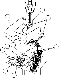
DEFROST CONTROL ASSEMBLY
Defrost Control assembly consists of Defrost Sensor and FUSE-M.
The Defrost Sensor works to defrost automatically. It is attached to the metal side of the Evaporator and senses its temperature. At 46F(8°C), it turns the Defrost Heater off.
Fuse-M is a safety device for preventing over-heating of the Heater when defrosting.
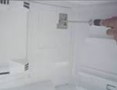
- Pull out the grille assembly. (Figure 1)
- Separate the connector with the Defrost Control assembly and replace the Defrost Control assembly after cutting the Tie Wrap. (Figure 2)
GRILLE ASSEMBLY DEFROST-CONTROL
ASSEMBLY
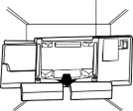
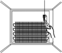
Figure 1 Figure 2
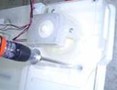
- LAMP
Unplug Refrigerator, or disconnect power at the circuit breaker.
If necessary, remove top shelf or shelves.
3-6-1 Refrigerator Compartment Lamp
- Release 2 screws.
- Hold both ends with your both hands and pull it downward to remove it.
- To remove the case lamp and cover lamp, release another 2 screws as following picture.
- Use a flat blade screwdriver as shown below to remove the cover lamp.
- To remove the LED Assembly, open the Hook part to pull it out as shown in the following picture.
-
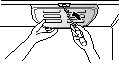
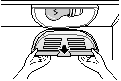
MULTI DUCT
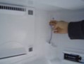
 Remove the upper and lower Caps by using a flat screwdriver, and remove 2 screws. (Figure 3)
- Disconnect the lead wire on the bottom position.
-
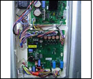
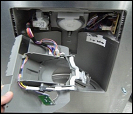
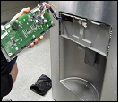
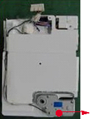
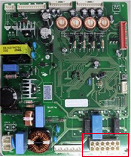
MAIN PWB
 WARNING : Unplug the refrigerator before removing the control board.
- Loosen the 3 screws on the PWB cover.

- Remove the PWB cover

 Case, lamp
Cover, lamp LED, Assembly
3-6-2 Freezer Compartment Lamp
- Unplug refrigerator power cord form outlet.
- Remove screw with driver.
- Grasp the cover Lamp,pull the cover downward.
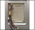 Disconnect wire harness and replace the main PWB in the reverse order of removal.


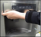
3-9 DISPENSER
- Disconnect funnel by pulling down and forward.
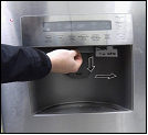
 Follow the steps in the pictures.
- Use a flat blade screwdriver at bottom side hole of the “Cover Assembly dispenser” to detach hooks of the bottom side.
-
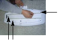
FUNNEL REPLACEMENT
- Pull up and out on the dispenser cover to remove.
- Remove 2 screws.
- Disconnect the wire harness.
- Replace in reverse order.
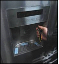 3) Hold the bottom side of the “Cover Assembly, dispenser” as shown in the picture, and pull and remove it. The cover dispenser is attached with a hook.
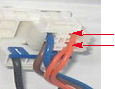
 CAUTION: When replacing the dispenser cover in the reverse order of removal, be careful that the lead wire does not come out and the water tube is not pinched by the dispenser cover, as shown in the picture below.
-
SUB PWB FOR WORKING DISPENSER
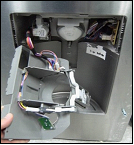
 1) Loosen the screw on the sub PWB.

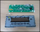
3-10 DISPLAY PWB REPLACEMENT
- Pull up and out on the dispenser cover to remove and replace PWB with dispenser cover.
- Pull the sub PWB down.
 Disconnect the wire harness and replace the sub PWB in the reverse order of removal.

-
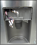
CAP DUCT REPLACEMENT
- Pull up and out on the dispenser cover to remove.
- Disconnect the wire harness.
- Remove the funnel.
- Replace in reverse order.
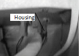
 Contract the Housing.


- CAP DUCT MOTOR REPLACEMENT
1) Separate the Housing of the Cap Duct Motor.
-
ICE CORNER DOOR REPLACEMENT
- Loosen the front screw as shown in the picture.
- Lift up the hinge with one hand.
- Pull out the Ice Corner Door with the other hand.

 Unscrew 3 screws to disassemble the motor.
- When replacing to a new Motor, always check position of the Duct Door and Link to install the Motor.
 Duct Door Link
Cap Duct Motor
NG Position
 Assemble on the screws.
-
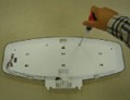
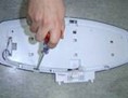
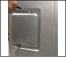
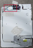
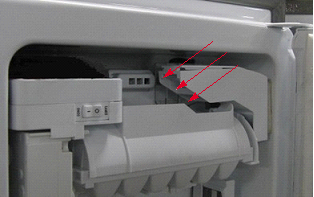
Icemaker replacement
- Remove the stainless screws marked in the picture below.
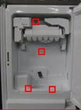
- Grasp the bottom of motor cover assembly and pull it out slowly.
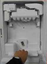
- Disconnect wire harness from wall of compartment.
CAUTION : Make sure that the wire harness shown below is positioned properly in the clips on the back of the cover, and taped in place. If this harness is loose it will not allow the motor housung assembly to fit flush to the door liner.
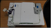
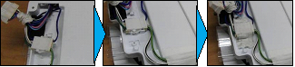

 In-door motor
-
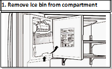
HOW TO REMOVE A ICE BIN
1) Grip the handles, as shown in the picture.
-
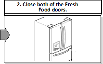
HOW TO INSERT A ICE BIN
- Insert the Ice Bin, slightly tilting it to avoid touching the Icemaker. (Especially, Ice-Detecting Sensor)


- Lift the lower part slightly.
- Take the Ice Bin out slowly.
-
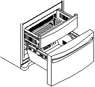
HOW TO REMOVE AND REINSTALL THE PULLOUT DRAWER
- Follow Steps to Remove
Step 1) Open the freezer door. Step 2) Remove the lower basket.
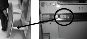 Step 3) Remove the two screws from the guide rails (one from each side).
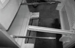
Step 4) Lift the freezer door up to unhook it from the rail support and remove.
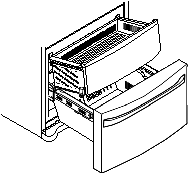
Pull both rails to full extension.
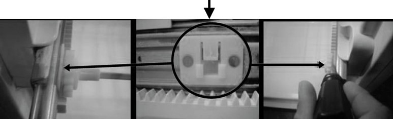
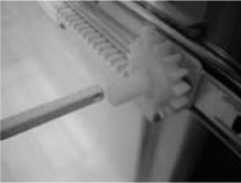
Step 5) First: Remove the gear from the left side first by releasing the tab behind the gear, place a screwdriver between the gear and the tab and pull up on the gear.
Second: Remove the center rail.
Third: Remove the gear from the right side by following the same steps for the left side.
NOTE: THIS TAB MUST BE PUSHED IN TO RELEASE THE GEAR.
-
Follow Steps to Reinstall
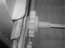
Step 1) Reinstall the right side gear into the clip.
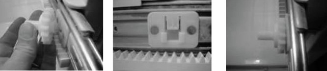
Step 2) Insert the rail into the right side gear. Gears do not need to be perpendicular to each other.
Step 4) The rail system will align itself by pushing the rails all the way into the freezer section.
Pull the rails back out to full extension.
Step 6) Reinstall the two screws into the guide rails (one from each side).
Step 3) Insert the rail into the left side gear, and insert the gear into the clip.
Step 5) Reinstall the freezer door by inserting the rail tabs into the guide rail.
Step 7) Reinstall the lower basket, and close the freezer door.
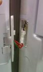
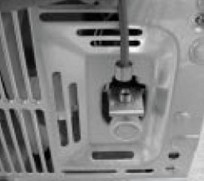
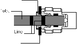
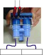
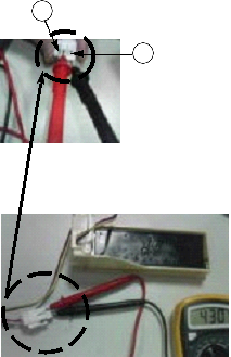
- WATER VALVE DISASSEMBLY METHOD
1) Turn off the water. Then separate the water line from the valve.
-
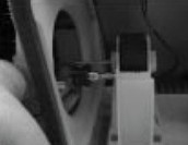
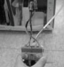
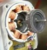
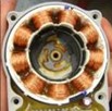
FAN AND FAN MOTOR DISASSEMBLY METHOD
- Using a short screwdriver, loosen one SCREW in DRAIN PIPE ASSEMBLY and one connected to the MOTOR COVER.
 MOTOR COVER


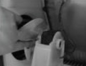
- Separate the Mechanical Cover and Valve Screw.

- Separate the housing and pull out the valve.


 Befrore disconnecting the water lines, place a towel under the water valve to catch any water that may come out. Pull out the clip and press the collet to separte the water line from the valve.
2) Pull and separate the FAN ASSEMBLY and MOTOR turning counterclockwise based on the MOTOR SHAFT.
FAN ASSEMBLY MOTOR


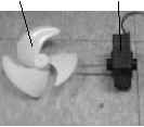

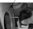
The assembly is in the reverse order of the disassembly and take special care for the following details.
- Be careful not to bend the tube during assembly.
- Press the WATER DISPENSER button until water pours out and check for leakage in the CONNECTOR TUBE (It differs by the water pressure but usually takes about 2 minutes until water pours out.)

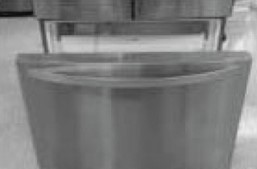
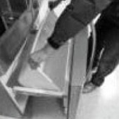
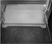
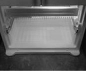
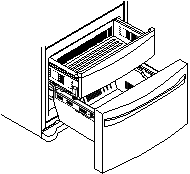
- PULL OUT DRAWER
To remove, pull the drawer out to full extension.
Lift the front of the drawer up, then pull it straight out.
To install, slightly tilt up the front and insert the drawer into the frame and push it back into place.
-
COMPRESSOR
-
Role
-
The compressor intakes low temperature and low pressure gas from the evaporator of the refrigerator and compresses this gas to high-temperature and high-pressure gas. It then delivers the gas to the condenser.
-
Note for Usage
- Be careful not to allow over-voltage and over-current.
- Do not drop or handle carelessly.
-
Keep away from any liquid.
If liquid such as oil or water enters the Cover PTC Compressor may fail due to breakdown of their insulating capabilities.
- Always use the Parts designed for the compressor and make sure it is properly attached to the compressor. Parts may appear physically identical but could have different electrical ratings. Replace parts by part number and model number. Use only approved substitute parts.
-
REMOVE THE COVER PTC
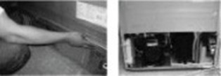
- Remove the Cover Back M/C
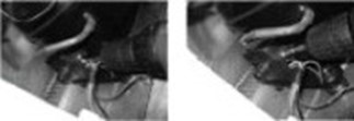
- Loosen two screws on comp base
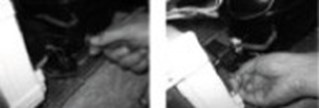
- Use a L-shaped flap tooll to pry off the cover
- Assembly in reverse order of disassembly
4-2 Introduction of E-Linear Compressor
 E-Linear compressor is run by mechanical part design through automatically varying the cooling power. The main parts consist of compressor and Sub PCB which controls the compressor. PCB authorizes constant voltage and constant frequency to the compressor and protects it.
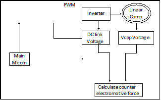
Control of Compressor Block Diagram
| Compressor Controller |
Signal |
|
Frequ |
|
-ency |
|
|
Counter elec- tromotive force |
|
Control Block Diagram of Compressor
-
Compressor operating pattern
 Drive half stroke after turning on initial power for 30 seconds. Then, slowly increase stroke and reach target input. Once reaching the target input, input naturally changes according to refrigerator load without any special control.
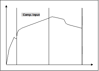

Interval 1) Half stroke interval – after initial running, stay at the initial value for 30 seconds
Interval 2) Running interval – Increase at every 0.8 till it reaches the target input; it takes about 3′ 45″
Interval 3) CVCF interval – Run by target voltage and main operating frequency and the input naturally changes according to refrigerator load


 PWBDADSSEMBDLYYD,DDD SMADRDTDBUUZZZZEEDDRD
PWBDD ASSEMBDLYYD,DD AMBIENDTDLEDDD
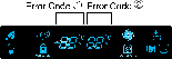
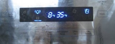
6-1. Error Code Summary
 WARNING: When you check the Resistance values, be sure to turn off the power.
And wait for the voltage-discharge sufficiently.
 NOTE) 3 hours before the error : Press the Ultra ICE button and Freezer button simultaneously 3 hours after the error : All errors, except for “Er rt”, “Er SS”, “Er IS(except for Icing sensor)”, “Er gF”, “Er It” error, are displayed.
“Er IS” which is displayed without input of user is the error of Icing Sensor.
NO
Error Detection CategoryError Display
Error Generation Factors
RemarkFreezer TemperatureFreezer Temperature1NormalityNoneNormal operation of Display2Freezer Sensor ErrorErFSShort or Disconnection of Freezer Sensor
Check each sensor and its connector.3Refrigerator Sensor ErrorErrSShort or Disconnection of Refrigerator Sensor4Defrosting Sensor ErrorErdSShort or Disconnection of Defrosting Sensor
5
Icing Sensor Error
Er
ISShort or disconnection of the sensor about Ice maker (Icing sensor, Ice maker sensor)6Pantry sensor errorErSSShort or Disconnection of Pantry Sensor7Room Temp Sensor ErrorErrtShort or Disconnectoin of Room temp.sensor
8
Ice maker kit defect
Er
It
Other Electric system error such as moter, gear, Hall IC, operation circuit within I/M kitWhen the ice does not drop even when the I/M Test S/W is pressed
(same as model applied Twisting Ice Maker before)
9Flow Meter(Sensor) Defect
Er
gFError of flow meter or water input or low water pressureError of flow meter or water input or low water pressure or flow meter connection
10
Poor Defrosting
Er
dHEven though it is passed
1 hour since then Defrosting, if Defrosting sensor is not over 46°F(8°C), it is causedTemperature Fuse Disconnection, Heater disconnection, DRAIN Jam, Poor Relay for Heater
11Abnormality of BLDC FAN Motor for Ice Making
Er
IFIt is caused when feedback signal isn’t over 65 seconds during BLDC FAN motor operating
Poor BLDC Motor connection, DRIVE IC, and TR
12Abnormality of BLDC FAN Motor for Freezer
Er
FFIt is caused when feedback signal isn’t over 65 seconds during BLDC FAN motor operating
Poor BLDC Motor connection, DRIVE IC, and TR
13Abnormality of BLDC FAN MOTOR For
Refrigerator
Er
rFIt is caused when feedback signal isn’t over 65 seconds during BLDC FAN motor operating
Poor BLDC Motor connection, DRIVE IC, and TR
14Abnormality of BLDC FAN Motor for Mechanic Room
Er
CFIt is caused when feedback signal isn’t over 65 seconds during BLDC FAN motor operating
Poor BLDC Motor connection, DRIVE IC, and TR
15
Communication Error
Er
CO
Communication Error between Micom of Main PCB and Display MicomPoor Communication connection,Poor TR of Transmitter and Receiver Tx/Rx between display and main board.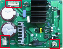
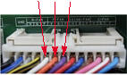
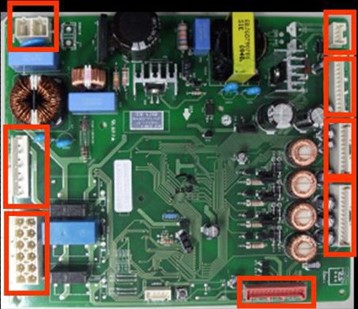 Main PCB
| P/No & MFG |
Picture |
|||
|
CON1 |
CON8 |
|||
|
CON6 |
||||
|
EBR65002701 (2010.02~) |
CON2 |
CON5 |
||
|
CON4 |
||||
|
CON3 |
||||
|
CON10 |
||||
|
EBR64173902 (2010.02~) Refer to 48Page |
CON203 CON201 |
CON2 |
||
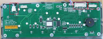
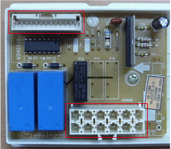


- Display PCB & Sub PCB
|
P/No |
Picture |
|||
|
Display PCB EBR65768601 (2010.02~) |
|
|||
|
CON104 |
CON102 CON101 |
|||
|
Sub PCB EBR60070704 (2010.02~) |
CON1 |
CON2 |
||
 Troubleshooting With Error Display
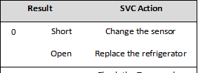
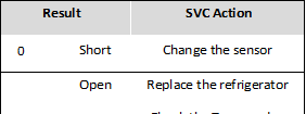
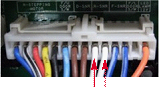
- Freezer Sensor Error (Er FS)
|
No |
Checking flow |
Result & SVC Action |
|
1 |
Check for a loose connection. |
|
|
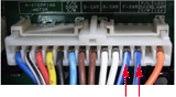
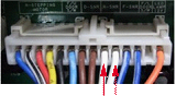
2 |
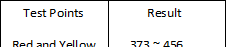
Check the Blue/White to
<CON6> |
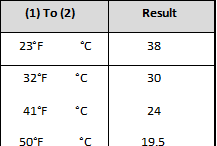
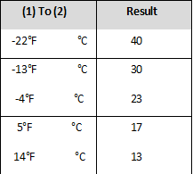
<Temperature table-1>
For example, |


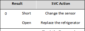
- Refrigerator Sensor Error (Er rS)
|
No |
Checking flow |
Result & SVC Action |
|
1 |
Check for a loose connection. |
|
|
2 |
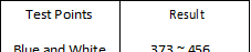
Check the White to White.
<CON6> |
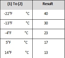
<Temperature table-2>
For example, |


- Icing Sensor Error (Er IS)
|
No |
Checking flow |
Result & SVC Action |
|
1 |
Check for a loose connection. |
|
|
2 |
Check the Blue to Blue.
<Display> <CON101> |
<Temperature table-1>
For example, |


- Defrost Sensor Error (F dS)
|
No |
Checking flow |
Result & SVC Action |
|
1 |
Check for a loose connection.
|
|
|
2 |
Check the Orange to Orange.
Check the Brown to Brown.
<CON6> |
<Temperature table-3>
For example, |


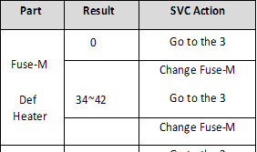 Defrost Heater Error (Er dH)
|
No |
Checking flow |
Result & SVC Action |
|
1 |
Check the Door gasket. |
|
|
2 |
Check the Defrost control part. Fuse M Sensor Def Heater |
|
|
3 |
Input Test 3 Mode. (Push the button 3 times) |
|
|
4 |
Check the Blue to Orange.
<CON3> |
|
|
5 |
Release the test mode. push the button 1 times. (normal) |
|
|
6 |
Check the Blue to Orange.
<CON3> |


- Freezer Fan Error (Er FF)
|
No |
Checking flow |
Result & SVC Action |
|
1 |
Reset the unit and Input Test 1 Mode. (Push the button 1 time) |
|
|
2 |
Open the freezer door and Check the air flow.
|
|
|
3 |
Check the Fan motor.
|
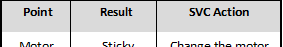
Rotate fan using your hand. It feel sticky, change the motor. (cause of ice or rust inside of motor) |
|
4 |
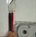
Check the Fan motor voltage. (1) (2) (3)
<CON4> |


- Icing Fan Error (Er IF)
|
No |
Checking flow |
Result & SVC Action |
|
1 |
Reset the unit and Input Test 1 Mode. (Push the button 1 time) |
|
|
2 |
Open the refrigerator door and Check the air flow.
|
|
|
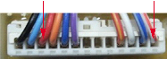
3 |
Check the Connector (Frozen caused the PCB short)
|
To protect ice short, add wire seal in connector. We developed new type connector, so order the new type.
Wire seal (Silicon) |
|
4 |
Check the Fan motor. (Frozen, Lock, ect.)
|
|
|
5 |
Check the Fan motor voltage. (1) (2) (3)
<CON4> |


- Condenser Fan Error (Er CF)
|
No |
Checking flow |
Result & SVC Action |
|
1 |
Reset the unit and Input Test 1 Mode. (Push the button 1 time) |
|
|
2 |
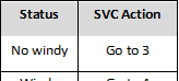
Check the fan rotating.
|
|
|
3 |
Check the Fan motor and surrounding.
|
Rotate fan using your hand. It feel sticky, change the motor. |
|
4 |
Check the Fan motor voltage. (1) (2) (3)
<CON4> |


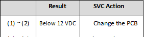
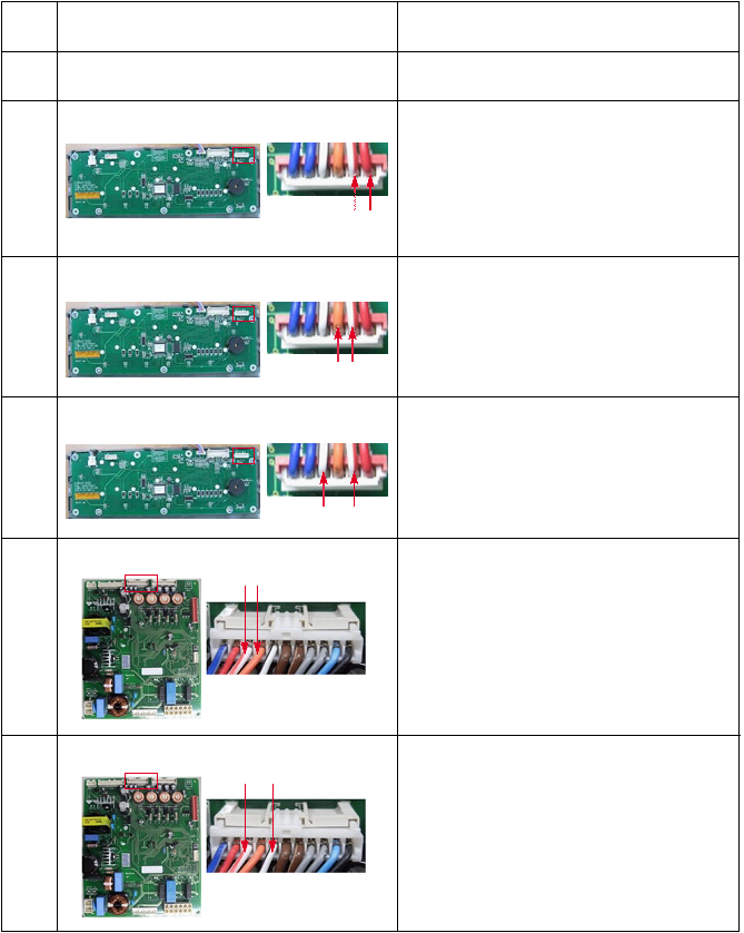
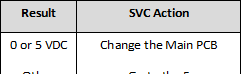
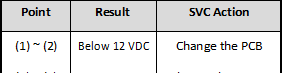
- Communication Error (Er CO)
No Checking flow
- Check the loose connection.
- Check the Red to White Red.
<CON101>
Result & SVC Action
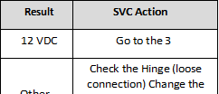
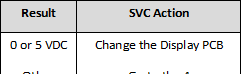 Check the Orange to Brown.
<CON101>
 Check the Orange to Red.
<CON101>
- Check the White/Red to Orange.
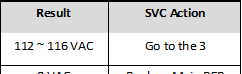
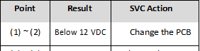
|
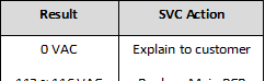
Result |
SVC Action |
|
0 or 5 VDC |
Change the Display PCB |
|
Other |
Go to the 6 |
<CON5>
- Check the White Red to White/Black.
|
Result |
SVC Action |
|
0 or 5 VDC |
Change the Main PCB |
|
Other |
Explain to customer |
<CON5>
 Troubleshooting Without Error Display
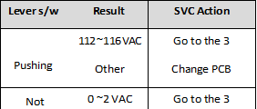 Cube mode doesn’t work
|
No |
Checking flow |
Result & SVC Action |
|
1 |
Check the loose connection. |
|
|
2 |
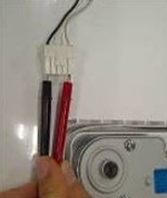
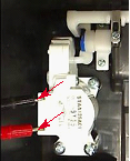
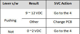
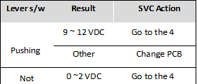
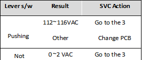
Check the Black to White. (While pushing the lever S/W)
<CON2> |
|
|
3 |
Check the RED to White Red. (While pushing the lever S/W)
<CON1> |
|
|
4 |
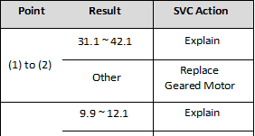
Check the resistance value.
<Ice Maker> (1) (2) (3) (4) <Geared Motor> <Dispenser Motor> |
|


 Crush mode doesn’t work
|
No |
Checking flow |
Result & SVC Action |
|
1 |
Check the loose connection. |
|
|
2 |
Check the Sky Blue to White. (While pushing the lever S/W)
<CON2> |
|
|
3 |
Check the RED to White Red. (While pushing the lever S/W)
<CON1> |
|
|
4 |
Check the resistance value.
<Ice Maker> (3) (1) (2) (4) <Geared Motor> <Dispenser Motor> |
|


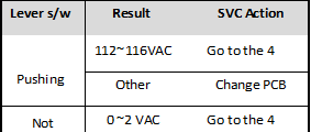
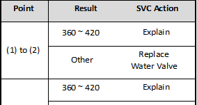
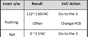 Water mode doesn’t work
|
No |
Checking flow |
Result & SVC Action |
|
1 |
Check the loose connection. |
|
|
2 |
Check the Purple to White. (While pushing the lever S/W)
<CON2> |
|
|
3 |
Check the Blue to Gray. (While pushing the lever S/W)
<CON3> |
|
|
4 |
Check the resistance value. (1) (2) (3) (4) Dispenser Ice Maker <Pilot Valve> <Water Valve> Machine Room In door |
|


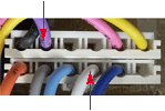


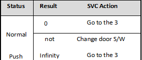
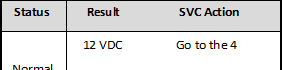
- Freezer room LED lamp doesn’t work
No Checking flow Result & SVC Action
- Check the Freezer door switch. If feel sticky, Change the door s/w.
 Check the door S/W resistance.
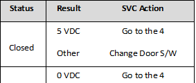 Check the Black to Sky blue.
<CON6>
 Check the Blue to Black.
<CON3>
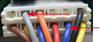
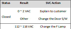
- Refrigerator room lamp doesn’t work
No Checking flow Result & SVC Action
- Check the Refrigerator door switch. If feel sticky, Change the door s/w.
 Check the door S/W resistance.
 Check the Black to Orange.
<CON6>
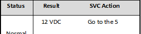 Check the Red to BLue.
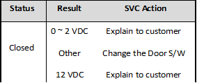 Check the Red to BLue.
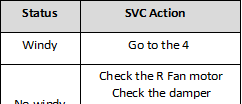

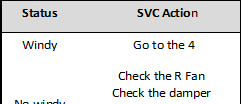
 Poor cooling in Fresh food section
|
No |
Checking flow |
Result & SVC Action |
|
1 |
Check the sensor resistance.
<CON6>
For example, |
|
|
2 |
Reset the unit and Input Test 1 Mode. (Push the button 1 time) |
|
|
3 |
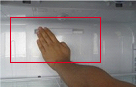
Open the fresh food door and Check the air flow. |
|
|
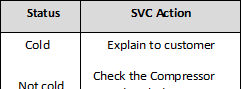
4 |
Check the air temperature. Cold or not ? |


No Checking flow
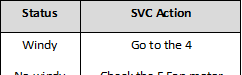
5 Damper checking method. Inputting TEST Mode, Check the damper and PCB.
(3)
(1)
Result & SVC Action
|
Test Mode |
Damper State |
SVC Action |
|
1 Mode |
Open |
Damper is normal. (Check the |
|
2 Mode |
Closed |
|
|
1,2 mode |
Not working |
Change the damper |
 (2) (4)
-
 Check the Fan motor. Rotate fan using your hand.
It feel sticky, change the motor. (Cause of ice or rust inside of motor)
 Check the R Fan motor voltage.
(1) (2) (3)
<CON4>
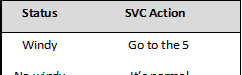
 Poor cooling in Freezer compratment
|
No |
Checking flow |
Result & SVC Action |
|
1 |
Check the sensor resistance.
<CON6>
For example, |
|
|
2 |
Reset the unit and Input Test 1 Mode. (Push the button 1 time) |
|
|
3 |
Open the freezer door and Check the air flow. |
|
|
4 |
Check the air temperature. Cold or not ? |


 Over cooling in Fresh food compartment
|
No |
Checking flow |
Result & SVC Action |
|
1 |
Check the sensor resistance.
<CON6>
For example, |
|
|
2 |
Reset the unit and Input Test 1 Mode. (Push the button 1 time) |
|
|
3 |
Open the refrigerator door and Check the air flow. |
|
|
4 |
Input Test 2 Mode and Check the air flow. (Push the button 1 time)
|
|
|
5 |
Check the damper resistance. (3) (1) (2) (4) |
|


- Reference
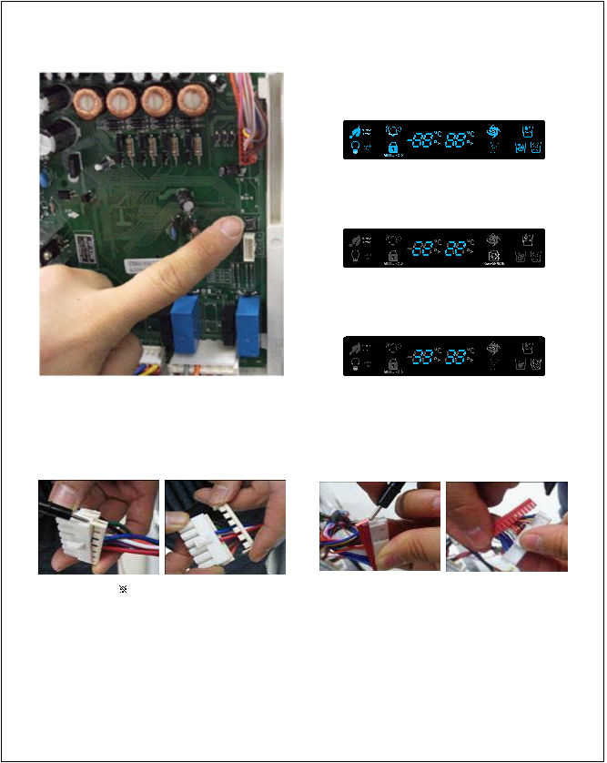 TEST MODE and Removing TPA
- How to make TEST MODE
If you push the test button on the Main PCB, the refrigerator will be enter the TEST MODE.
- 1 time : Comp / Damper / All FAN on (All things displayed)
-
2 times : Damper closed
(22 22 displayed)
-
3 times : Forced defrost mode
(33 33 displayed)
Main PWB
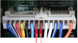
-
How to remove Terminal Position Assurance (TPA)
<AC TPA> <DC TPA>
After measure the values, you should put in the TPA again.
-
Wire Color
BL : Blue WH : White
BO : Bright Orange BK : Black
BN : Brown PR : Purple RE : Red
GN : Green SB : Sky Blue GY : Gray
BL/WH : Blue & White WH/RD : White & Red YL/BK : Yellow & Black
- TEMPERATRUE CHART – FRZ AND ICING SENSOR
| TEMP |
RESISTANCE |
VOLTAGE |
| -39°F (-40°C) |
73.29 |
4.09 V |
| -30°F (-35°C) |
53.63 |
3.84 V |
| -21°F (-30°C) |
39.66 |
3.55 V |
| -13°F (-25°C) |
29.62 |
3.23 V |
| -4°F (-20°C) |
22.33 |
2.89 V |
| 5°F (-15°C) |
16.99 |
2.56 V |
| 14°F (-10°C) |
13.05 |
2.23 V |
| 23°F (-5°C) |
10.10 |
1.92 V |
| 32°F (0°C) |
7.88 |
1.63 V |
| 41°F (5°C) |
6.19 |
1.38 V |
| 50°F (10°C) |
4.91 |
1.16 V |
| 59°F (15°C) |
3.91 |
0.97 V |
| 68°F (20°C) |
3.14 |
0.81 V |
| 77°F (25°C) |
2.54 |
0.67 V |
| 86°F (30°C) |
2.07 |
0.56 V |
| 95°F (35°C) |
1.69 |
0.47 V |
| 104°F (40°C) |
1.39 |
0.39 V |


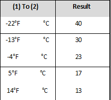
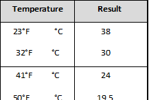
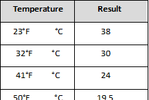
- TEMPERATRUE CHART – REF AND DEF SENSOR
| TEMP |
RESISTANCE |
VOLTAGE |
| -39°F (-40°C) |
225.1 |
4.48 V |
| -30°F (-35°C) |
169.8 |
4.33 V |
| -21°F (-30°C) |
129.3 |
4.16 V |
| -13°F (-25°C) |
99.30 |
3.95 V |
| -4°F (-20°C) |
76.96 |
3.734 V |
| 5°F (-15°C) |
60.13 |
3.487 V |
| 14°F (-10°C) |
47.34 |
3.22 V |
| 23°F (-5°C) |
37.55 |
2.95 V |
| 32°F (0°C) |
30 |
2.67 V |
| 41°F (5°C) |
24.13 |
2.40 V |
| 50°F (10°C) |
19.53 |
2.14 V |
| 59°F (15°C) |
15.91 |
1.89 V |
| 68°F (20°C) |
13.03 |
1.64 V |
| 77°F (25°C) |
10.74 |
1.45 V |
| 86°F (30°C) |
8.89 |
1.27 V |
| 95°F (35°C) |
7.40 |
1.10 V |
| 104°F (40°C) |
6.20 |
0.96 V |


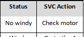
Step 1) Open PWB cover Step 2) Check for blinking frequency of LED, PWB
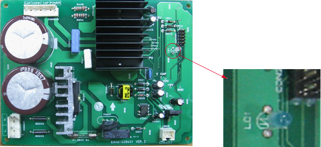
If compressor is normal, it does not blink
: Refer to the next page to find out what actions to take according to how many times LED blink


| No |
LED operating condition |
Cause |
Service guideline |
|
|
1 |
LED two – time repetiton
on – on – off – on – on – off – on – on – off repeating |
PCB part defect (piston overrun) |
|
|
|
LED four – time repetiton
on – on – on – on – off – on – on – on – on – off repeating |
1.After resetting |
|||
|
power, check if it is |
||||
|
running normal |
||||
|
2.If the same |
||||
|
2 |
outlet clogging |
symptom arises after the first action, replace PCB |
||
|
3.If the same |
||||
|
symptom arises after |
||||
|
the second action, |
||||
|
replace compressor |
||||
|
LED five – time repetiton
on – on – on – on – on – off – on – on – on – on – on – off repeating |
1. After resetting |
|||
|
power, check if it is |
||||
|
running normal |
||||
|
2. If the same |
||||
|
3 |
piston constraint |
symptom arises after the first action, replace PCB |
||
|
3. If the same |
||||
|
symptom arises after |
||||
|
the second action, |
||||
|
replace compressor |
||||
|
LED six – time repetiton
on – on – on – on – on – on – off – on – on – on – on – on – on – off |
repeating |
1. After resetting |
||
|
power, check if it is |
||||
|
running normal |
||||
|
4 |
circuit overcurrent error |
If the same symptom arises after the first action, replace PCB If the same symptom |
||
|
arises after the |
||||
|
second action, |
||||
|
replace compressor |
||||
|
LED seven- time repetiton
on – on – on – on – on – on – on – off – on – on –on – on – on – on– on – off repeating |
1.After resetting |
|||
|
power, check if it is |
||||
|
5 |
PCB part defect (IPM) |
running normal 2. If the same symptom arises after the first action, |
||
|
replace PCB |
||||


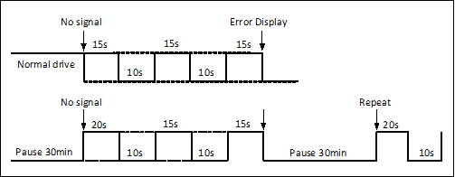
- How to check the Fan-Error
(1) EBR650027
After sending a signal to the fan, the MICOM checks the BLDC fan motor s lock status. If there is no feedback signal from the BLDC fan, the fan motor stops for 10 seconds and then is powered again for 15 seconds. To determine that there is a fan motor malfunction,
this process is repeated 3 times. If the fan motor is determined to be defective, the error code will be shown in the display for 30 minutes.
At this point, the process will be repeated until the fan motor operates normally. If normal operation is achieved, the error display is erased and the MICOM is reset automatically.
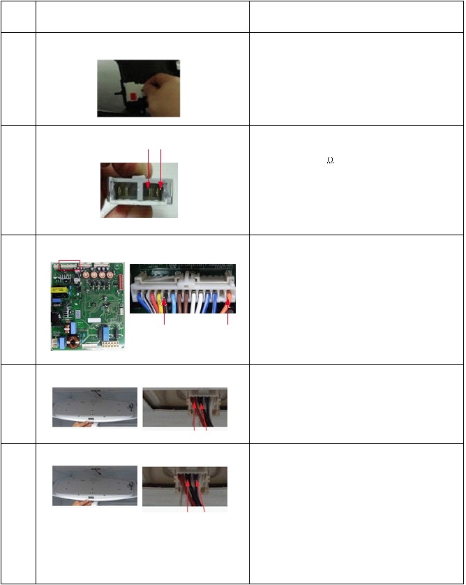
 COMPONENT TESTING INFORMATION
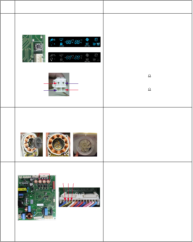
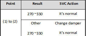
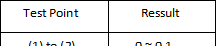
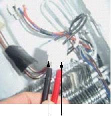
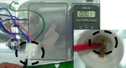
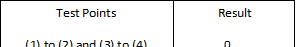
Defrost Controller Assembly
|
Function |
|
|
|
How to Measure (Fuse-M) |
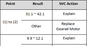
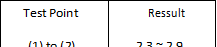
(1) to (2) |
Set a ohmmeter to the 2 housing pin. Measure the 2 pin connected to Fuse-M. If the ohmmeter indicate below 0.1ohm fuse-m is a good condition, But infinitely great ohm Fuse-M is disconnection |
|
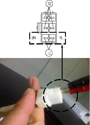
How to Measure (Sensor) |
(1) to (2) |
Set a ohmmeter to The 2housing pin. Measure the 2 pin connected to Sensor. If the ohmmeter indicate When check the ohm at other temperature Check the sensor manual. |
|
Standard |
Fuse-M (at all temperature)
|
Sensor (at room temperature)
|


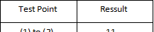
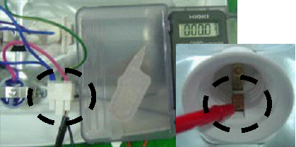
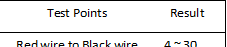
- Sheath Heater
|
Function |
Sheath heater is a part for defrost. All heating wire is connected to only one line. So we can decide part is defect or not when we check the resistance. |
|
How to Measure |
(1) (2) Set a ohmmeter connect to The 2 housing pin. Measure the 2 pin connected to Sheath Heater. If the ohmmeter indicate (V°øV)/Watt=R is good condition, ex) when watt=350w, voltage=115v R=(115°ø115)/350=38 Sheath heater is disconnection |
|
Standard |
Sheath heater (at all temperature)
|


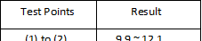
 Door Heater Assembly
| Function |
The heater is |
designed |
to |
prevent |
the raising dew from door. |
|||
| How to | ||||||||
| Measure | ||||||||
|
1 |
|
|||||||
|
3 |
2 |
|
||||||
|
6 |
4 |
5 |
||||||
|
7 |
||||||||
| 8 | ||||||||
|
9 |
||||||||
| Standard |
|
|||||||


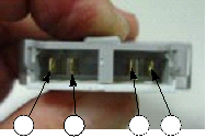

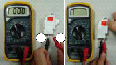
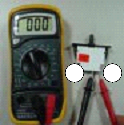
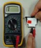
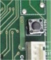
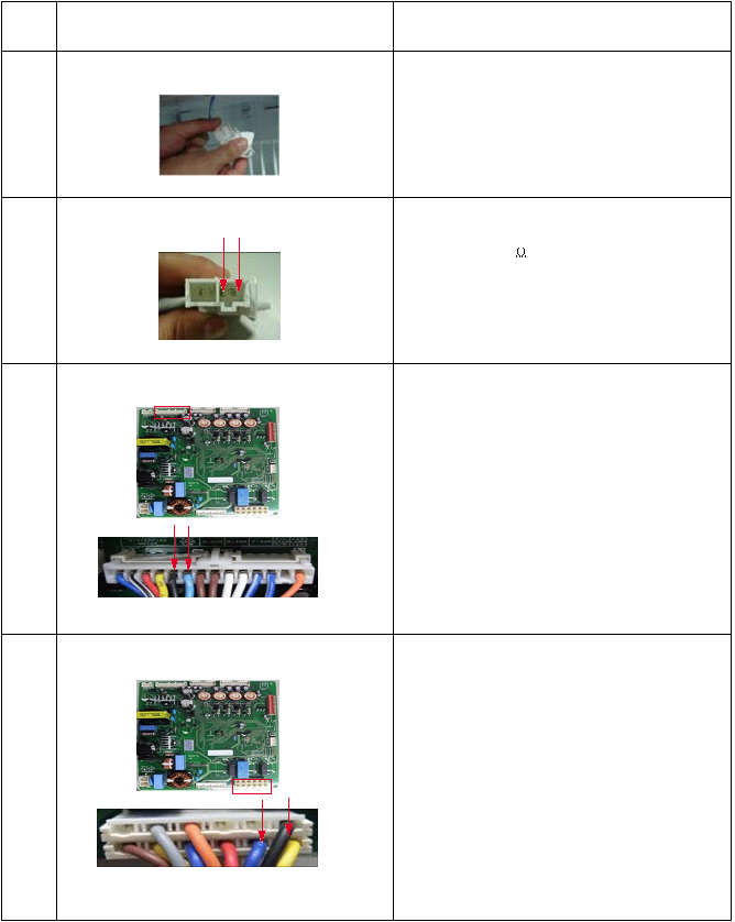
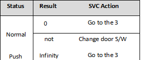
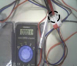
- Door Switch
|
Function |
The switch sense if the door open or close.
When the door open, internal contact operate on and off moving plunger of door switch up and down. |
|
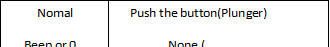
How to Measure |
<Switch, Freezer> <Switch, Refrigerator> Button (Plunger) 1 2 3 4 1 2 3 4 3 4 2 1 Beep Beep Check the resistance between connectors 1, 2 and 3, 4 .It means check whether or not applying an electric current. If there is resistance, it means the switch not inferiority |
|
Standard |
Multimeter beep – Switch F,R
|


 Dispenser DC Motor
|
Function |
– Dispenser DC Motor : When customer push the dispenser button, Pull duct door and abstract from ice bank. |
|
How to Measure |
(1) (2) Dispensor DC Motor |
|
Standard |
Dispenser DC Motor
|

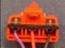
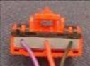
 AC Motor ASSEMBLY
|
Function |
The In-door motor of AC motor assembly pushes ices to the dispenser. |
|
How to Measure |
< In-door Motor > < In-door Motor >
(1) (2) (1) (3) Check the resistance between connectors (In-door motor 1, 2) and (In-door motor 1, 3). It means check whether or not applying an Electric current. If there is resistance, it means the geared motor or solenoid is not inferiority |
|
Standard |
Geared Motor Cube Solenoid
|


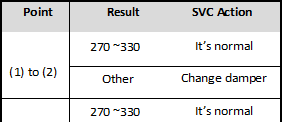
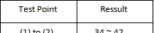
 Damper
|
Function |
The damper supplies the cold air at freezer room to chillroom by using the damper’s plate. Chillroom is colder than before when damper’s plate is open. When damper’s plate is close, chillroom’s temperature will rise. |
|
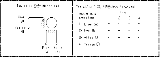
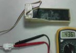
How to Measure |
< Damper Circuit > 1 Blue 1 Blue
3 White
3 Yellow Check the 1 , 3 < extension >
Check the 2 , 4 Check the 1 , 3 Check the resistance between connectors 1,3 and 2,4 .It means check whether or not applying an electric current. If there is resistance, it means the damper not inferiority |
|
Standard |
Damper
|


 Lamp Socket
|
Function |
The lamp socket connect cover lamp assembly to lamp. The lamp socket fix lamp and unite lamp and cover lamp assembly. The lamp socket supply electric source to lamp also. |
|
How to Measure |
(1) (2) (3) (4) Check the resistance between connector of housing and connector of lamp socket. It means check whether or not applying an electric current. If there is resistance it means the lamp socket is not inferiority. |
|
Standard |
|

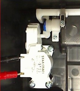
 Flow Sensor
|
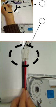
Function |
Flow Sensor (in machine room) Count the water quantity from city water to water filter in refrigerator |
|
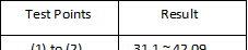
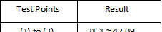
How to Measure |
Flow Sensor (in machine room) |
|
Standard |
|

- TROUBLESHOOTING
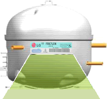
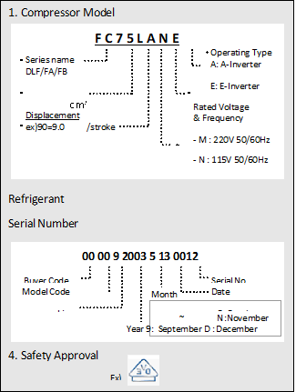
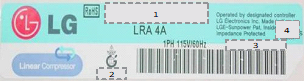
- INFORMATION OF LINEAR COMPRESSOR
 The information tag provides compressor model, refrigerant, serial number and safety approval
Compressor Label

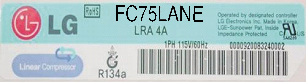
 Name Plate
 Size : 90mm X 20mm
 There are two types of controllers used in the linear compressor system.
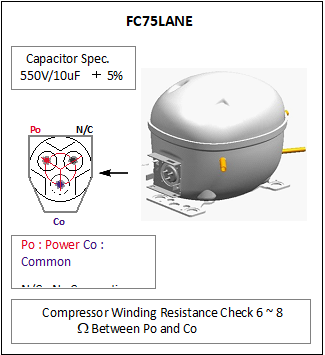
- The “E”-inverter system is used with the FC75LANE compressor.
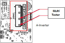
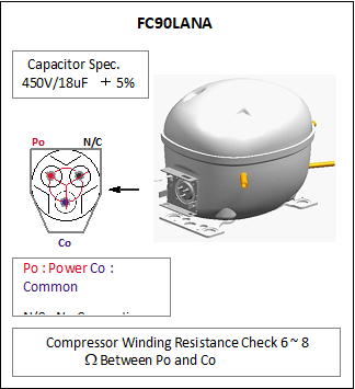
- The “A”-inverter system is used with the FC90LANA compressor.
 Refrigerator
Comp Drive
Compressor


 FC75LANE
E-Inverter System


 FC90LANA
A-Inverter System
*VVVF : Variable Voltage Variable Frequency
**CVCF : Constant Voltage Constant Frequency


 To reduce noise level, the piston stroke is slowly increased to full power during start up.
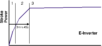 Step 1) Start up – Half stroke interval for first 30 seconds.
Step 2) Ramp up – Stroke increases every 0.8sec until maximum stroke length is reached (about 3 min, 15 sec)
Step 3) CVCF interval – 180V / 60Hz

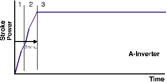 Step 1) Start up – Half stroke interval for first 20 seconds.
Step 2) Ramp up – Stroke increases until maximum stroke length is reached (about 1 min, 40 sec)
Step 3) VVVF interval – target voltage and frequency controlled by Control Board signals
 There are 6 protection logics designed to protect the linear compressor system. When a failure is detected, the compressor will shut and will try to restart after a set period of time for each type of failure. The LED located on the inverter drive PCB will flash the appropriate code to indicate the detected failure. This code will continue to flash until the unit is disconnected from the power source.
Inverter Error Codes
App.RequirementWaiting TimeThe number of LED flashesFCT0A-Inv.Compressor current and voltage error.20 sec.1Stroke TripE-Inv.
A-Inv.Piston stroke overrun detected.1 min.2Locked Piston TripE-Inv.
A-Inv.Piston is locked.2 min. 30 sec.5Current TripE-Inv.
A-Inv.Current overload detected.2 min. 30 sec.6IPM FaultE-Inv.
A-Inv.High current detected due to IPM failure.2 min. 30 sec.7Communication ErrorA-Inv.Miscommunication with Refrigerator08

 Bridge Diodes converts 115V AC (Alternating current) to 115V DC (Direct current) The Voltage Multiplying circuit then increases the 115V DC to 230V DC.
Then the IPM (Intelligent Power Module) converts the 230V DC to 230V AC.
The converted AC power can be regulated to any required voltage and frequency.
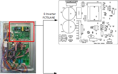

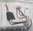
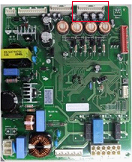
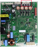
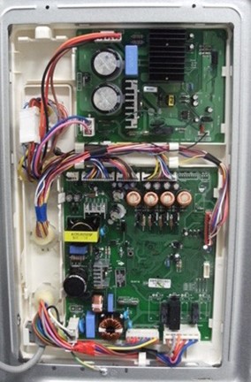
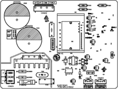
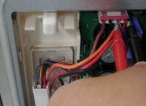
 There are two PCB located behind the PCB cover. One is the main PCB, and the other is the driver PCB the linear compressor.
A-Inverter FC90LANA

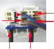
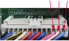
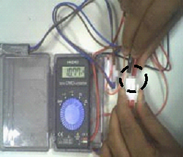
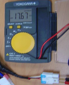
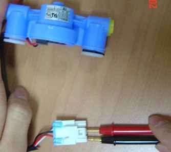
 Measure the voltage at locations on the connector (as shown picture) with a multi-tester.
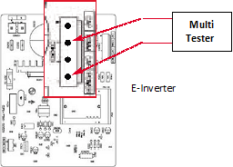
IPM Voltage Check
 To ensure proper diagnosis, make sure that the unit has been plugged in for at least 10 min.
 To determine if the compressor is receiving the proper voltage, check the PCB output voltage during operation.
 Normal operating voltage will be between 80V AC and 180V AC.
Note : Higher voltage readings may occur under “heavy” load conditions.

 Insulation check : Check for infinite Ohms between all compressor terminal and ground.


LG Linear Compressor
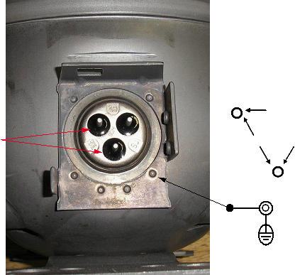 NOTE : Any Terminal to Ground should read Inf ( ~ )

 Inf (~)
6 ~ 8 6 ~ 8 Inf (~)
GN
GND


-
SERVICE DIAGNOSIS CHART
| COMPLAINT |
POINTS TO BE CHECKED |
REMEDY |
| No Cooling. |
|
|
| Cools poorly. |
|
|
| Food in the Refrigerator is frozen. |
|
|
| Condensation or ice forms inside the unit. |
|
|
| Condensation forms in the Exterior Case. |
|
|
| There is abnormal noise. |
|
|
| Door does not close well. |
|
|
| Ice and foods smell unpleasant. |
|
|


 Other possible problems:
|
Check if frost forms in the freezer. |
Not defrosting |
Check Components of the defrosting circuit. |
||
|
Check the refrigeration system. |
The system is faulty. |
Perform sealed system repair. |
||
|
Check the Thermistor. |
The operation of the Thermistor is incorrect. |
Replace the Thermistor. |
||
- REFRIGERATION CYCLE
 Troubleshooting Chart
|
CAUSE |
STATE OF THE UNIT |
STATE OF THE EVAPORATOR |
TEMPERATURE OF THE COMPRESSOR |
REMARKS |
|
|
LEAKAGE |
PARTIAL LEAKAGE |
Freezer compartment and Refrigerator don’t cool normally. |
Low flowing sound of Refrigerant is heard and frost forms in inlet only. |
A little higher than ambient temperature. |
|
|
COMPLETE LEAKAGE |
Freezer compartment and Refrigerator don’t cool normally. |
Flowing sound of refrigerant is not heard and frost isn’t formed. |
Equal to ambient temperature. |
|
|
|
CLOGGED BY DUST |
PARTIAL CLOG |
Freezer compartment and Refrigerator don’t cool normally. |
Flowing sound of refrigerant is heard and frost forms in inlet only. |
A little higher than ambient temperature. |
|
|
WHOLE CLOG |
Freezer compartment and Refrigerator don’t cool. |
Flowing sound of refrigerant is not heard and frost isn’t formed. |
Equal to ambient temperature. |
|
|
| MOISTURE CLOG |
Cooling operation stops periodically. |
Flowing sound of refrigerant is not heard and frost melts. |
Lower than ambient temperature. |
|
|
| DEFECTIVE COMPRESSION |
COMP- RESSION |
Freezer and Refrigerator don’t cool. |
Low flowing sound of refrigerant is heard and frost forms in inlet only. |
A little higher than ambient temperature. |
|
|
NO COMP- RESSION |
No compressing operation. |
Flowing sound of refrigerant is not heard and there is no frost. |
Equal to ambient temperature. |
|
|
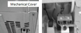
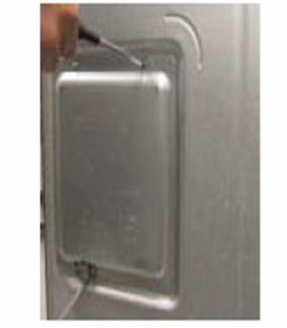
- Cleaning
There is no need for routine condenser cleaning in normal Home operating environments. If the environment is particularly greasy or dusty, or there is significant pet traffic in the home, the condenser should be cleaned every 2 to 3 months to ensure maximum efficiency.
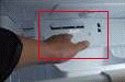
 If you need to clean the condenser: Remove the mechanical cover.
 Use a vacuum cleaner with a soft brush to clean the grille, the open areas behind the grille and the front surface area of the condenser.
 Replace the mechanical cover.
- SEALED SYSTEM DIAGNOSIS
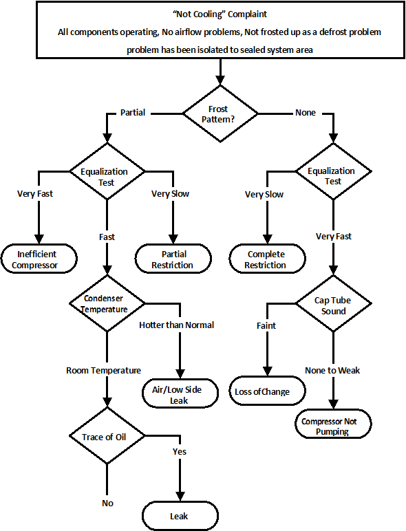
 (The equalization test is trying to restart a compressor using a start kit after it has been operating.)
-
ICEMAKER OPERATING METHOD AND TROUBLE SHOOTING
- Icemaker’s Basic Operating Method
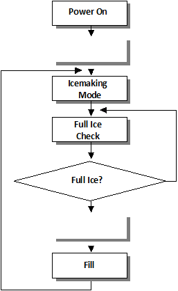

 Adjusts Ice Tray to Start Position with power on.
-
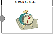
 Waits until water becomes ice.

 For cold air circulation, Ice tray will be on a slightly tilt one hour after
ice-making mode begins. Atilt ice tray means icemaker’s normal operation.
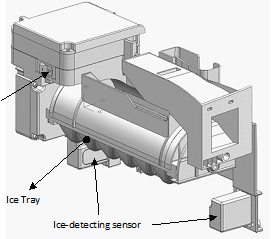
 If water becomes ices in the ice tray, Ice-detecting sensor check if the ice bin is full.

 Twist the ice tray to drop ice into the ICE BIN.
 Supply water to the ice tray by operating the solenoid valve.
-
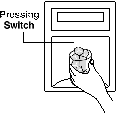
 To force water to supply to the ice tray, or check icemaker’s condition press and hold the FILL Key for about 3seconds.
In the test mode, The icemaker will run through 3 stages step by step
: Harvest

Fill water
Ice making
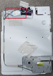
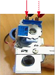
To reset the icemaker’s operation, set the power switch OFF position and back it to ON position.
 Power Switch
Icemaker Unit
- ICE MAKER FUNCTIONS
- Icemaking Mode
- Icemaking Mode begins right after the ice tray fills with water.
-
Icemaker waits until water becomes ice in the ice tray.

Ice-detecting sensor checks if the ice bin is full every 2min.
-
Harvest Mode
At least in 110min, since icemaker begun icemaking mode, Icemaker starts to twist the ice tray to drop ices into the Ice bin. (After installation, at least 1day is needed to make ices)

If the icemaker never drop ices to the ice bin though water becomes ices in the ice tray, check the real temperature of compartment. (not temperature on display)Icemaker needs below 0°F to drop ices to ice bin.
-
-
Fill/Park Position
Once the normal harvest mode has been completed, the water solenoid will be activated.
-
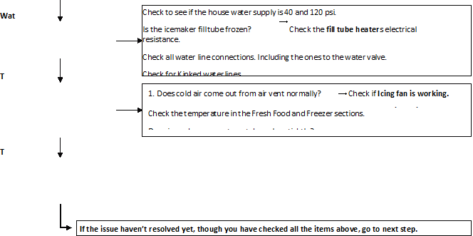
Trouble Shooting Ice & Water system Issues
- Icemaker not making ice or not making enough ice (Environmental Diagnosis)

Icemaker can’t make ices itself. Basically, water, temperature and time are needed.
- Water : If no Water, then no Ice.
- Temperature : The compartment, where the icemaker is located, has to be at least 1°F so that icemaker dumps ices to the bin.
- Time : At least 80 minutes must be passed to make one series of ices after water comes into icemaker.

 Test Mode should not be carried out before checking below.
|
Not making ice |
||||
| er | ||||
|
Is the icemaker’s tray filled with water or Ice? |
No |
|||
| emperature |
Yes |
|||
|
Is the temperature below 10 degrees F in the icemaker compartment. |
No |
|
| ime |
Yes |
|
|
Advise the customer on how long it takes to make ice. |
||
|
No |
|
|
-
Icemaker not making ice or not making enough ice (Icemaker Unit & Ice-detecting sensor Diagnosis)

Icemaker Unit and Ice-detecting sensor Diagnosis
The icemaker unit and Ice-detecting sensor is programmed to be diagnosed.
Follow the procedure step by step to check to see if icemaker and Ice-detecting sensor is working normally.
 Icemaker Unit
Ice-detecting sensor
Test Switch
1stSTEP (Icemaker Unit Diagnosis)
Press the test switch (located on the bottom of the icemaker head) for about 3 seconds. The icemaker tray should turn to the twisting position and return to the flat position, the fills with water.
 CAUTION: Be sure that the ice tray is not filled with water before pressing fill key.
2stSTEP (Ice-detecting sensor Diagnosis)

-
Icemaker not making ice or not making enough ice (Other Suspected Items)
Strongly suspect items below If the issue remains yet, though all the diagnosis for icemaker has been carried out.
- Cap duct bad sealing
- Defective thermal sensor in the icemaker compartment
- Not cold icemaker compartment area (sealed system)
-
Not Dispensing Ice

Clogged Ice In the Ice Bin (suspected items)
-
Customer haven’t used ice dispenser over a week.

Resolution : the ices gets stuck if customer doesn’t use ice dispenser.In this case, empty the ice bin and wait until the new ices are stacked in the ice bin.
-
Temperature of icemaker compartment is not cold enough.

Resolution : Check ice fan, sealed system, cap duct, vent and other items related to temperature. -
Cap duct doesn’t seal the air properly.

Resolution : Possibly, warm air could get into the compartment and make ices get stuck. Replace the cap duct with new one. -
In-door geared motor doesn’t work

Resolution : Change the in-door geared motor and test it.
-
The water comes out of fill cup and the water get into the ice bin.

Resolution : The water pressure from shutoff valve is too high.Recommend to use regulator to the customer and close the shutoff valve slightly.

Clogged Ices In the Chute (suspected items)
-
Cap duct doesn’t seal the air properly.

Resolution : Possibly, warm air could get into the compartment and make ices get stuck. Replace the cap duct with new one.
- DESCRIPTION OF FUNCTION & CIRCUIT OF MICOM
-
FUNCTION
- Function
-
When the appliance is plugged in, it is set to 37°F for Refrigerator and 0°F for freezer.
You can adjust the Refrigerator and the Freezer control temperature by pressing the ADJUST button.
- When the power is initially applied or restored after a power failure, it is set to Control temperature Previously.
- If you do not press any button after turning on the power, only the water, Ice type, lock Icon that has been selected will be turned on and all other LEDs on the Dispenser Panel will be turned off Within 60 seconds. (Power Save Mode)
- If you press a button, only the water, Ice type, lock Icon that has been selected will be turned on and all other LEDs on the Dispenser Panel will be turned off Within 20 seconds. (Power Save Mode)
- If you do not want to use the Power Save Mode, you can change the Mode by pressing the ULTRA ICE Button and Freezer TEMP button simultaneously for more than 5 seconds.
-
How to Toggle the Display between °F & °C
1. The initial setting is °F and the display temperature mode can be changed from °F to °C or °C to °F by pressing and holding the FRZ TEMP and the REF TEMP keys at the same time for over 5 seconds.
-
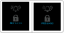
Alarm/Lock function (dispenser and display button lock)
- When the refrigerator is first turned on, the buttons are not locked. “LOCK” is deactivated with light off.
-
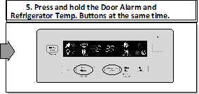
To lock the display, the dispenser, and the control panel, press
and hold the LOCK button for 3 seconds. “LOCK” is activated with light on.
- The LOCK button is the only control feature that remains active in the locked state. The buzzer sound, other control buttons, and the dispenser are deactivated.
- To release from the locked state, press and hold the LOCK button again for 3 seconds.
-
 If you don t hold the Alarm/Lock button more than 3 seconds,
Alarm function will be changed and alarm for opened door will be on/off same as alarm icon indicating.
 Ex) In selecting “LOCK”
Ex) In selecting “LOCK” again
-
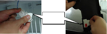
Filter condition display function
- There is a replacement indicator light for the filter cartridge on the dispenser.
- Water filter needs replacement once six months or of using water filter.
- When the Water Filter Icon lights on, you must exchange the filter.
-
After replacing the filter, press and hold the lock button for more than 3 seconds .
After then water Filter icon turn off with reset status.
Classification
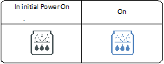 Filter Status Display
- Ultra Ice selection

 Please select this function for quick freezing.
 When you press the Ultra Ice Button, the Ultra ICE ICON will be turned on again.
- Ultra Ice function automatically turns off after a fixed time passes.
-
Dispenser use selection
You can select water or ice.

 When you press the Water Button, the Water Icon will be selected.
- When you press the Ice button, the Cube/Crush ICON will be selected in order.


 Hold your cup in the dispenser for a few seconds after dispensing ice or water to allow the last pieoes of ice or drops of water to fall into the cup.
-
When after initially establ ishing the water comes out, the water tank inside fills and until at the time of quality the hour is caught.
-
DISPENSER LIGHT
– Whenever pressed the LIGHT button, DISPLAY is changed as belows.


Normal status : Ambient Light is off.
 AUTO status : Detecting the lighting of room by LIGHT SENSOR, Ambient Light is on and off automatically. ON status : Ambient Light is on continuously.
For all status : When dispenser is operated, DISPENSER LIGHT is on.
-
CONTROL OF FREEZER FAN MOTOR
- Freezer fan motor has high and standard speeds.
- High speed is used at power-up, for Ultra Ice, and when refrigerator is overloaded. Standard speeds is used for general purposes.
- To improve cooling speed, the RPM of the freezer fan motor change from normal speed to high.
- High speed (2700RPM) : Initial power on or load corresponding operation, Ultra Ice. Normal speed (2400RPM) : General working conditions.
-
Cooling Fan Motor
- The cooling fan is switched ON and OFF in conjunction with the compressor.
- The cooling fan Motor has high and standard speeds. (When room temper rapture more high then 38°C speed is high)
-
The Failure sensing method is the same as in the fan motor of the freezing fan motor(refer to failure diagnosis function table for failure display).
-
Ice Compartment Fan
-
- The Icing Fan is controlled by the the sensor on the top of the ice compartment.
- The Failure sensing method is the same as in the fan motor of the freezer (refer to failure diagnosis function table for failure display)
-
Refrigeration room Fan Motor
- The refrigeration room fan is switched ON and OFF in conjunction with the refrigeration room temperature.
- The Failure sensing method is the same as in the fan motor of the freezing fan motor (refer to failure diagnosis function table for failure display).
-
Ultra ICE
- The purpose of this function is to intensify the cooling speed of freezer and to increase the amount of ice.
- Whenever selection switch is pressed, selection/release, the Icon will turn ON or OFF.
- If there is a power outage and the refrigerator is powered on again, Ultra ICE will be canceled.
- To activate this function, press the Ultra ICE key and the Icon will turn ON. This function will remain activated for 24 hrs. The first one hours the compressor, Freezer Fan and Icing Fan(high speed) will be ON. The next 23 hours the Ice room will be controlled at the lowest temperature. And icing fan run high speed. After 24 hours or if the Ultra ICE key is pressed again, the Ice room will return to its previous temperature. And icing fan run standard speed.
-
During the first 1 hours :
- Compressor, Freezer Fan and Icing Fan(high speed) run continuously.
- If a defrost cycle begins during the first 30 minutes of Ultra ICE, the Ultra ICE cycle will complete its cycle after defrosting has ended.
If the defrost cycle begins when Ultra ICE has run for more than 30 minutes, Ultra ICE will run for 40 minutes after the defrost is completed.
- If Ultra ICE is pressed during defrost, Ultra ICE Icon is on but this function will start seven minutes after defrost is completed and it shall operate for one hours.
- If Ultra Ice is selected within seven minutes after compressor has stopped, the compressor (compressor delays seven minutes) shall start after the balance of the delay time.
- Compressor, Freezer Fan and Icing Fan(high speed) run continuously.
- For the rest of the 23 hours, the Ice room will be controlled at the lowest temperature. And icing fan run high speed.
-
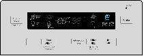
How to set the display mode and cancel it
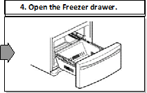
- With the refrigerator door open, keep pressing the Refrigerator Temp Button and ULTRA ICE Button more than 5 seconds, then it goes to the display mode with Special Beep Sound.
- Perform the same way again to cancel the display mode.
- All freezing units do not work at the display mode.
-
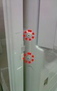
Energy Saver
- If you want additional power save, you can turn on energy saver (some heater off for anti-dew).
- To turn on or off the energy saver function, press Energy Saver Button for more than 3 seconds.
- We recommend using energy saver function when you go out for quite a long time and are out of the rainy season.
Pillar Heater Off

 Pillar Heater On
- Defrosting (removing frost)
- Defrosting starts each time the COMPRESSOR running time Betwee 7~50 hours.
- For initial power on or for restoring power, defrosting starts when the compressor running time reaches 4 hours.
- Defrosting stops if the sensor temperature reaches 46.4°F(8°C) or more. If the sensor doesn’t reach 46.4°F(8°C) in 1 hours, the defrost mode is malfunctioning. (Refer to the defect diagnosis function, 8-1-15.)
- Defrosting won’t function if its sensor is defective (wires are cut or short circuited)
-
Defect Diagnosis Function
- Automatic diagnosis makes servicing the refrigerator easy.
- When a defect occurs, the buttons will not operate; but the tones. such as ding. will sound.
- When the defect CODE removes the sign, it returns to normal operation (RESET).
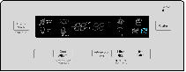
- The defect CODE shows on the Refrigerator and Freezer Display.

-
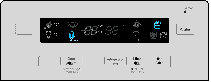
LED check function: If simultaneously pressing Ultra Ice button and freezing temperature adjustment button for a second, display LED graphics on. If releasing the button, the LED graphic displays the previous status.
You can check the error code Within 3-hour Period from initial error
-
Auto pantry
- The temperature control will automatically start upon the selected Auto Pantry temperature control.
- You can adjust the Pantry control with three different temperature ranges by pressing the activate button.


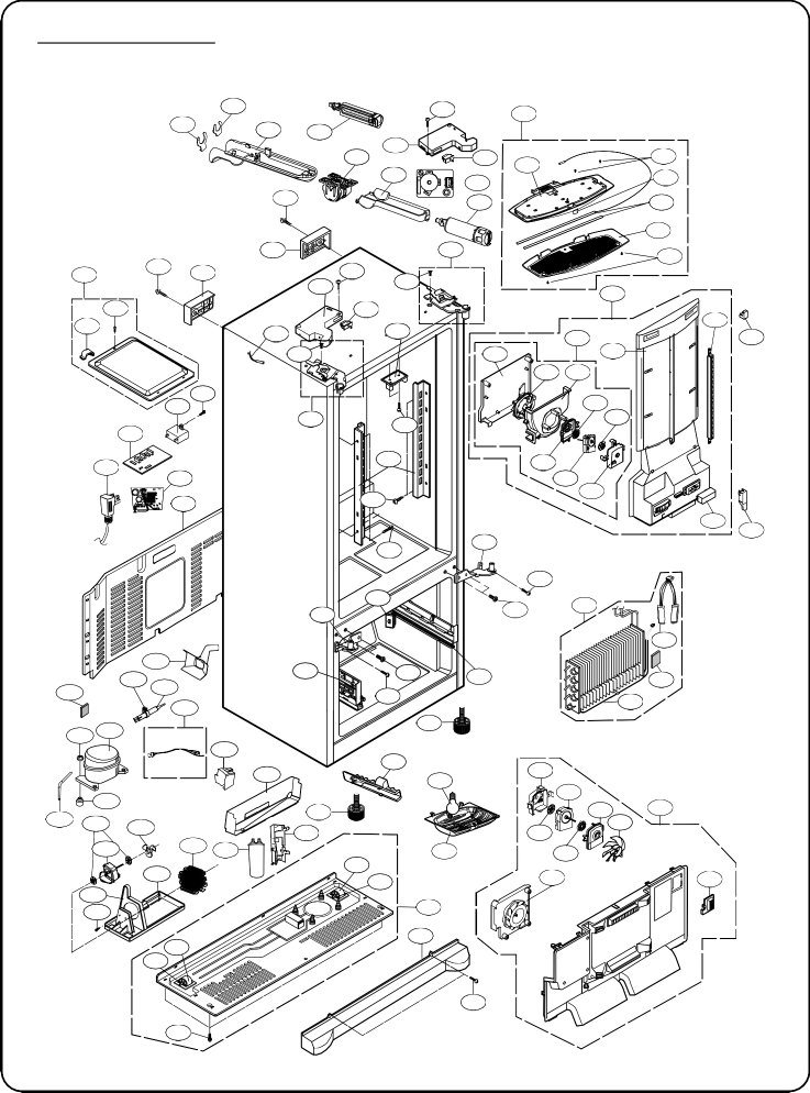
CASE PARTS
CAUTION : Use the part number to order the part, not the position number.
603E
603C
626A
624E
624D
207B
S03
402A
503E
503D
S11
S01
624C
500P
624A
503G
409D
501F
S02
S01
103A
103B
207A
S03
402A
B01
271B
120A
158A
S11
501G
610D
B01
406D
405G
329B
145A
120C 282G
120B
405E
411A
500A
410J
500H
313A
S02
271D S10
145B
S11
262B
405D
404B
405C
405H
405F
405I
282F
S11
262H
406B
B02
S14
302B
400A
316A
314A
300A
318A
105A
317A
303A
304A
249D
S14
B02 249C
106A
408A
316B
310B
312A
309B 329C
420A
323B
410G
312C
106A
290A
315B
145G
409B
503F
405H
405F
404A
405C
405B
329A
332C
319C S20
319A
315C
315A
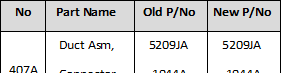
407A
610C
315C
315B
103C
S17
B04


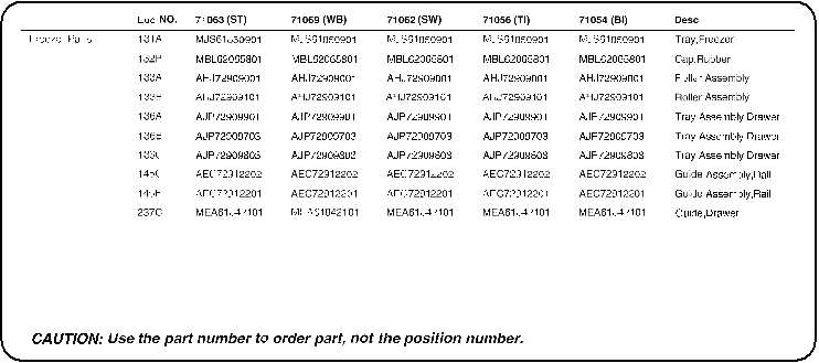
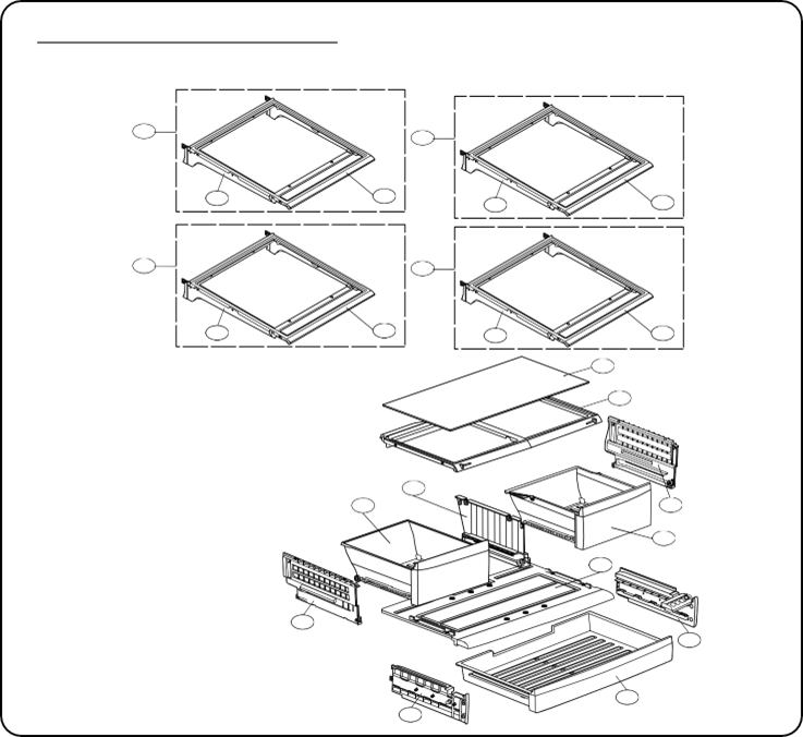
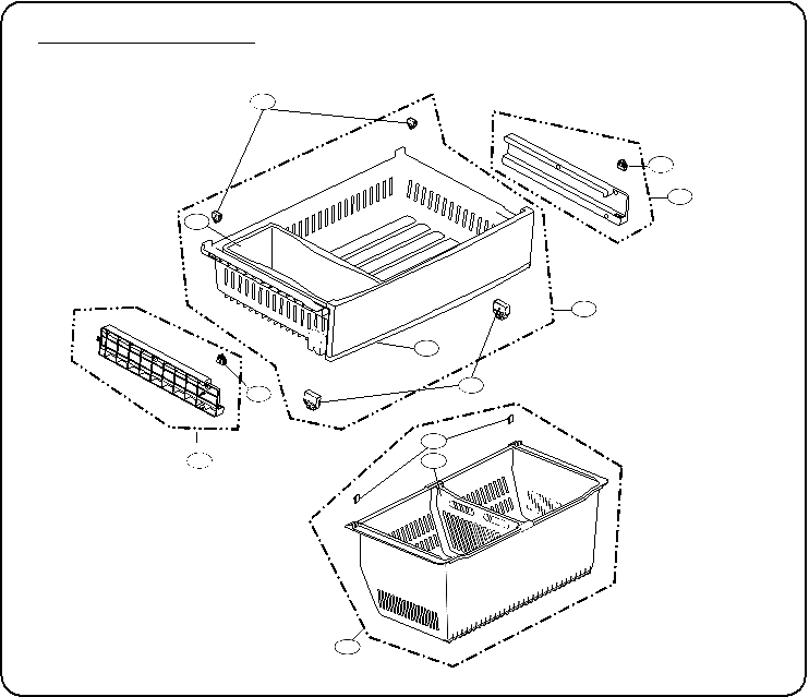 FREEZER PARTS
CAUTION : Use the part number to order part, not the position number.
133B
133B
145C
131A
136C
136B
133B
133A
132P
145F 237C
136A
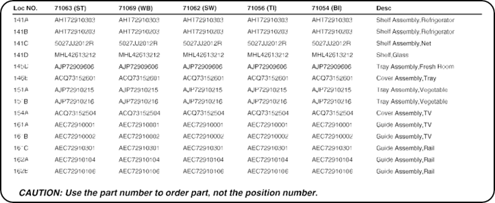
 REFRIGERATOR PARTS
CAUTION : Use the part number to order part, not the position number.
141A
141A


141A
141A


141D
154A
151A
161C
161B
151B
146E
161A
162B
145D
162A
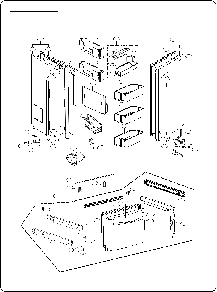
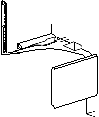
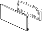
DOOR PARTS
CAUTION : Use the part number to order part, not the position number.
230B
241K
241A
230A
231B
233B
241C
241B
233A
231A
235A
212G
241K
B06
B06
241D
241G
241D
312B
243C
B06
241E
B06
243D
262C
243B
244A
615A
619B
603B
603C
244A
243A
262E 262C
250A
250H
250F
250B
250B
200A
249P
201A
249E
B06
B06 212D
249J
203A
249F
249K


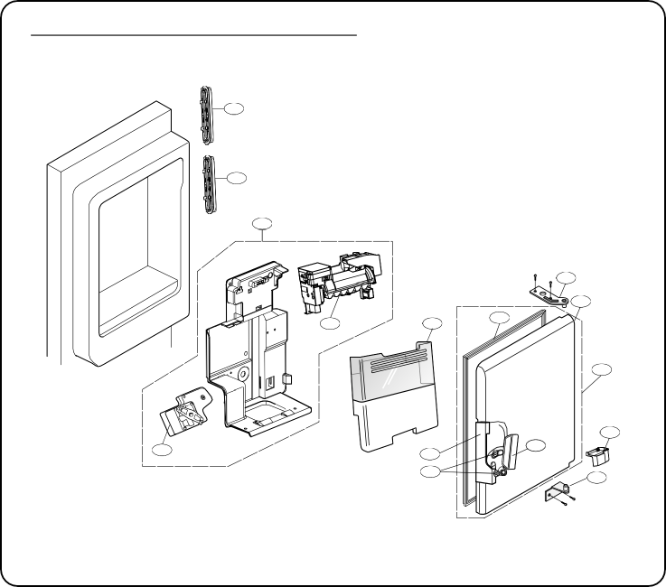
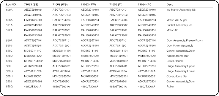
630J
630J
612A
630F
630B
600A
611A
630C
630A
606A
630E
630D
630H
630Q
630G
– 10 –
REFRIGERATOR SERVICE MANUAL PDF =
Your articles are extremely helpful to me. Please provide more information! http://www.hairstylesvip.com