4-1. Function for failure diagnosis  40
40
4-1-1) TEST MODE  40
40
4-1-2) DISPLAY FUNCTION OF COMMUNICATION ERROR  41
41
4-1-3) SELF-DIAGNOSTIC FUNCTION  42
42
4-1-4) DISPLAY FUNCTION OF LOAD CONDITION  45
45
4-1-5) EXHIBITION MODE SETTING FUNCTION  46
46
4-1-6) OPTION SETTING  46
46
4-1-7) Option TABLE  49
49
4-2. Diagnostic method according to the trouble symptom  51
51
4-2-1) IF THE TROUBLE IS DETECTED BY SELF-DIAGNOSIS  52
52
4-2-2) IF FAN DOES NOT OPERATE  60
60
4-2-3) IF ICE MAKER DOES NOT OPERATE  61
61
4-2-4) IF DEFROST DOES NOT OPERATE (F,R DEF  62
62
4-2-5) IF POWER IS NOT SUPPLIED  63
63
4-2-6) IF COMPRESSOR DOES NOT OPERATE  64
64
4-2-7) WHEN ALARM SOUND CONTINUOUS WITHOUT STOP  65
65
4-2-8) IF PANEL PCB DOES NOT WORK NORMALLY  67
67
4-2-9) IF PANTRY PANEL PCB IS NOT WORKING  68
68
4-2-10) WHEN REFRIGERATOR ROOM LAMP DOES NOT LIGHT UP  69
69
4-2-11) IF ICE WATER IS NOT SUPPLIED  70
70
 4-2-12) IF WATER IS NOT SUPPLIED 71

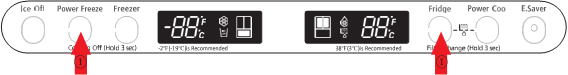
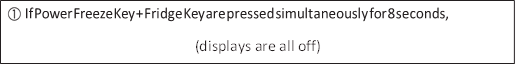
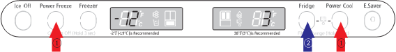
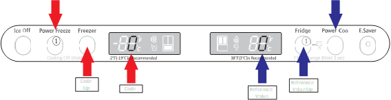
4-1-1. Test mode (manual operation / manual defrost function)
- If Power Freeze & Fridge temperature control Key on the front of panel are pressed simultaneously for 8 seconds , it will be changed to the test mode and all displays on the front of panel will be off.
-
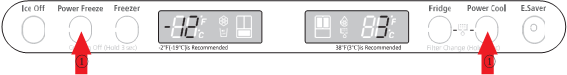
If any key on the front of panel is pressed within 15 seconds after the test mode, it will be operated as below sequence :
manual operation(fresh food compartment)
 manual defrost of fresh food compartment(rd)
manual defrost of fresh food and freezer compartments (Fd) Cancel(Display all off).
 -
If any key on the front of panel is not pressed within 15 seconds after the test mode, the test
mode will be canceled and it will be returned to previous mode.
- Manual operation function
- Manual operation function

 1-1) If any key is pressed once in test mode, blinks “FF” on the display and it indicates the refrigerator has entered the manual operation. At this moment, buzzer beeps as an alarm.
1-2) If manual operation is selected, comp will run at once without 5 minutes delay in any mode. If the refrigerator is on the defrost cycle at the moment, defrost will be finished and manual operation will begin.
(Be careful if manual operation get started at the moment of comp off, over load could be occurred)
1-3) If manual operation works, comp & f-fan operate continuously for 24 hours and fresh food compartment will be controlled by the setting temperature.
1-4) When the manual operation runs, setting temperature will be selected automatically as below: freezer compartment  (-25
(-25 ), fresh food compartment
  (1
(1 ).
).
1-5) During manual operation, Power Freeze & Power Cool function will not be worked. If a function is selected, the power function icon of the selected function will be off automatically after 10 seconds.
1-6) Manual operation can be canceled during manual operation by turning on the appliance after power off(reset) or choosing the step 4) test cancel mode.
1-7) Alarm(0.25 sec ON/ 0.75 sec OFF) will beep continuously until manual operation is completed and there is no function to make the sound stop.
- Manual defrost(fresh food compartment) function


2-1) If any key is pressed one more time during manual operation(fresh food compartment), “rd” shows in the display and then manual operation will be canceled at once and fresh food compartment will be defrosted.
2-2) At this moment, alarm beeps for 3 seconds(0.1 sec ON/ 1 sec OFF) during manual defrost(fresh food compartment) function.
- Simultaneous manual defrost(fresh food and freezer compartments) function


3-1) If any key is pressed one more time during manual defrost(defrost of fresh food compartment, “rd”), “Fd” shows on the display and then fresh food and freezer compartments defrost will operate.
Manual defrost of Fresh food and freezer compartments are followed by manual defrost freezer compartment.
3-2) At this moment, alarm beeps for 3 seconds (0.5 sec ON/ 0.5 sec OFF) during manual defrost function of fresh food and freezer compartment.
-
Test cancel mode
4-1) During defrosting of fresh food and freezer compartments simultaneously, if the display panel change to the test mode and test button is pressed one more time, defrosting of fresh food and freezer compartments will be canceled at the same time and will return to the normal operation.
Or, all test functions will be canceled by turning main power ON again after it OFF.
4-1-2. Display function of Communication error
-
Display function when Panel

MAIN MICOM communication has error
1-1) If there is no answer for 10 seconds after the panel micom received the requirement of communication, “Pc – Er” display on the panel PCB will be ON/OFF alternately until the communication error is canceled. (0.5 sec ALL ON, 0.5 sec ALL OFF alternately)

 (0.5 sec ALL ON, 0.5 sec ALL OFF alternately)
2-1) If there is no answer for 20 seconds after the main micon received the requirement of communication from load MICOM, “Lc – Er” display on the panel PCB will be ON/OFF alternately until the communication error is canceled.

 (0.5 sec ALL ON, 0.5 sec ALL OFF alternately)
2-2) Also pantry room display will be ON/OFF alternately until the communication error is canceled.
(0.5 sec ALL ON, 1.5 sec ALL OFF alternately)
 LOAD MICOM communication has error
4-1-3. Self-diagnostic function
-
Self-diagnostic function in the Initial power ON
1-1) Micom operates self-diagnostic function to check the temperature sensor condition within 1 second when the refrigerator turned On initially.
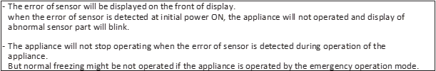
1-2) If bad sensor is detected by the self-diagnostic function, the applicable display LED will blink for 0.5 sec.
At this moment, there is no beep sound.(Refer to self-diagnostic CHECK LIST)
1-3) Self-diagnostic button is recognized only when the error is displayed by the bad sensor.
Display does not operate normally but temperature control will be controlled by the emergency operation.
1-4) When the error is detected by self-diagnosis, the error can be canceled automatically if all troubled sensors are corrected or Self-diagnostic function key (Power Freeze + Power Cool ) are pressed simultaneously for 8 seconds.
(Return to normal display mode)


- Self-diagnostic function during normal operation
2-1) If Power Freeze + Power Cool Key are pressed simultaneously for 6 seconds during normal operation, the temperature setting display will operate for 2 seconds (ON/OFF 0.5sec each).
If Power Freeze + Power Cool Key are pressed simultaneously for 8 seconds (including above 2 seconds), self-diagnostic function will be selected.
2-2) At this moment, self-diagnostic function will be returned with buzzer sound ‘ding-dong’.
If there is an error, display of error will be operated for 30 seconds and then return to normal condition whether problem is corrected or not.
(Refer to self-diagnosis CHECK LIST)
2-3) Input by button is not accepted during self-diagnostic function.
* Self-diagnosis CHECK LIST
| NO |
Trouble item |
Display LED |
Trouble contents |
| 1 |
Ice Maker Sensor Error |
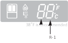
R-1- |
ICE MAKER SENSOR part error |
| 2 |
R-Sensor Error |
R-1- |
FF SENSOR part error |
| 3 |
R-DEF-Sensor Error |
R-1- |
FF defrost SENSOR part error |
| 4 |
R-FAN Error |
R-1- |
FF inner fan motor part error |
| 5 |
Ice Maker Error |
R-1- |
ICE MAKER operation error |
| 6 |
R-DEF.Error |
R-1- |
FZ defrost part error |
| 7 |
Ambient-Sensor Error |
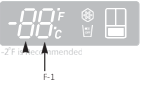
F-1- |
External SENSOR part error |
| 8 |
F-Sensor Error |
F-1- |
FZ SENSOR part error |
| 9 |
F-DEF-Sensor Error |
F-1- |
FZ defrost SENSOR part error |
| 10 |
F-FAN Error |
F-1- |
FZ inner fan motor part error |
| 11 |
C-FAN Error |
F-1- |
Machine room fan motor part error |
| 12 |
F-DEF. Error |
F-1- |
FZ defrost part error |
| 13 |
Pantry-Damper-Heater Error |
R-10- |
Damper Heater open/wire error |
| 14 |
Pantry-Sensor Error |
R-10- |
Pantry Room SENSOR part error |
| 15 |
Panel Main MICOM communication Error |
F-10- |
Panel Main MICOM communication error |
| 16 |
L M communication Error |
F-10- |
LOAD Main MICOM communication error |


 F-10
F-10
F-1
R-10
 R-1
R-1

* Self-diagnostics check list
|
LED |
Item |
Trouble contents |
Diagnostic method |
|
R-1- |
Ice Maker Sensor Error |
Display error : separation of sensor housing part, contact error, disconnection, short circuit Display error of detecting temperature of sensor: more than than |
When checking the voltage of MAIN PCB CN90 #3 |
|
R-1- |
R-Sensor Error |
When checking the voltage of MAIN PCB CN30#6  CN75#1:shall be between 4.5V~1.0V CN75#1:shall be between 4.5V~1.0V |
|
|
R-1- |
R-DEF-Sensor Error |
When checking the voltage of MAIN PCB CN30#7  CN75#:shall be between 4.5V~1.0V CN75#:shall be between 4.5V~1.0V |
|
|
R-1- |
R-FAN Error |
Display error during operation of applicable fan motor : Feed Back signal line contact error, separation of motor wire, motor error | Voltage of MAIN PCB CN75 Orange  Gray shall be between 7V~12V |
|
R-1- |
Ice Maker Error |
Display error : ice making kit is harvested more than 3 times and level error ** Apply to the applicable Ice Maker model. |
After replacing ice maker, check the operation by turning the appliance ON again. |
|
R-1- |
R-DEF. Error |
Display error : separation of fresh food compartment defrost heater housing part, contact error, disconnection, short circuit or temperature fuse error. Display error : the defrosting does not finish though fresh food compartment defrost is heating continuously for more than 80 minutes. |
After separating MAIN PCB CN70,CN71 from PCB, check the resistance value between CN70 White  CN71 Orange shall be 102(441) ohm CN71 Orange shall be 102(441) ohm  7%. (Resistant value is varied by the input power) 7%. (Resistant value is varied by the input power)Check 0 Ohm : heater short, |
|
F-1- |
Ambient-Sensor Error |
Display error : sensor housing separation, contact error, disconnection, short circuit Display error by detecting temperature of sensor: more than  (+65°C) or less than (+65°C) or less than  (-50°C) (-50°C) |
When checking the voltage of MAIN PCB CN32#1  #4 : shall be between 4.5V~1.0V. #4 : shall be between 4.5V~1.0V. |
|
F-1- |
F-Sensor Error |
When checking the voltage of MAIN PCB CN30#3  CN75#1:shall be between 4.5V~1.0V CN75#1:shall be between 4.5V~1.0V |
|
|
F-1- |
DEF-Sensor Error |
When check the voltage of MAIN PCB CN30#4  CN75#1:shall be between 4.5V~1.0V CN75#1:shall be between 4.5V~1.0V |
|
|
F-1- |
F-FAN Error |
Display error during operation of applicable fan motor : Feed Back signal line contact error, motor wire separation, motor error | Voltage of MAIN PCB CN75 Yellow  Gray shall be between 7V~12V. |
|
F-1- |
C-FAN Error |
Display error during operation of applicable fan motor : Feed Back signal line contact error, motor wire separation, motor error | Voltage of MAIN PCB CN75 Sky-blue  Gray shall be between 7V~12V. |
|
F-1- |
F-DEF. Error |
Display error : separation of freezer compartment defrost heater housing part , contact error, disconnection, short circuit or temperature fuse error. Display error : the defrosting does not finish though fresh food compartment compartment defrost is heating continuously for more than 70 minutes. | After separating MAIN PCB CN70,CN71 from PCB, check the resistant value between CN70 brown  CN71 Orange shall be 102(220) ohm CN71 Orange shall be 102(220) ohm  7%. (Resistant value is varied by input power) Check 0 Ohm : heater short,  Ohm : wire / bimetal Open. |
|
R-10- |
Pantry-Damper-Heater Error |
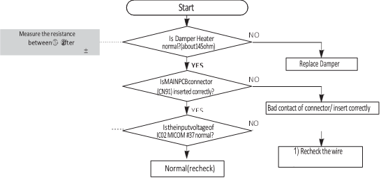
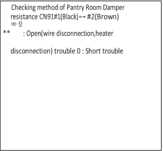
Display error when open error is detected by damper heater : separation of Damper Heater housing part, contact error, disconnection, short circuit | After separating MAIN PCB CN91from PCB, check the resistant value between Black  brown wire shall be 145 ohm  7%. Check 0 Ohm : heater short,  Ohm : wire / bimetal Open. |
|
R-10- |
Pantry-Sensor Error |
Display error : separation of sensor housing, contact error, disconnection, short circuit. Display error by detecting temperature of sensor: more than |
When checking the voltage of MAIN PCB CN30#8  #9 : shall be between 4.5V~1.0V. #9 : shall be between 4.5V~1.0V. |
|
F-10- |
Panel |
Display “oP/LC-Er” in the panel with alarm : MICOM MAIN LOAD communication error MICOM MAIN PANEL communication error LC-Er is displayed when the Option is not equivalent with the right value | Actually, it is desirable to recheck the condition with the oscilloscope after replacing Main and Panel PCB. |
|
F-10- |
Load |


 (-50°C)
 CN90#4 : shall be between 4.5V~1.0V.


 Ohm : wire / bimetal Open.


 (+65°C) or less than
  (-50°C)
 Main communication Error
 Main communication Error


4-1-4. Display function of Load condition
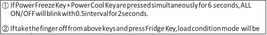
- If Power Freeze Key + Power Cool Key are pressed simultaneously for 6 seconds during normal operation, the temperature setting display of fresh food and freezer compartments will blink ALL ON/OFF with 0.5 for 2 seconds.
- At this moment, If Fridge Key after Power Freeze Key + Power Cool Key is pressed, load condition display mode will be returned with alarm.
-
Load condition display mode shows the load that micom signal is outputting.
However, It means that micom signal is outputting, it does not mean whether load is operating or not. That is to say that though load operation is displayed, load could not be operated by actual load error or PCB relay error etc.
- Load condition display function will maintain for 30 seconds and then normal condition will be returned automatically.
 Load condition display is as below.
F-10 R-10

 * Load mode Check list
| Display LED |
Display contents |
Operation contents |
| R-1- | R-FAN High |
When fresh food compartment fan high operates, applicable LED ON |
| R-1- | R-FAN Low |
When fresh food compartment fan low operates, applicable LED ON |
| R-1- | R-DEF Heater |
When fresh food compartment defrost heater operates, LED ON |
| R-1- | Start Mode |
Initial power ON refrigerator, LED ON |
| R-1- | Overload condition |
When ambient temperature is more than 93 (34°C), LED ON |
| R-1- | Low temperature condition |
When ambient temperature is less than 72 (22°C), LED ON |
| F-1- , ALLLEDOff | Normal Condition |
When ambient temperature is between 73 (23°C) ~ 91 (33°C), LED ON |
| R1- | Exhibition Mode |
Display mode, LED ON |
| F-1- | COMP. |
When compressor operates, applicable LED ON |
| F-1- | F-FAN High |
When freezer compartment fan high operates, applicable LED ON |
| F-1- | F-FAN Low |
When freezer compartment fan low operates, applicable LED ON |
| F-1- | F-DEF Heater |
When freezer compartment defrost heater operates, LED ON |
| R-10- | C-FAN High |
When compressor fan high operates, applicable LED ON |
| R-10- | C-FAN Low |
When compressor fan low operates, applicable LED ON |
| F-10- | French Heater |
When french heater operates, applicable LED ON |
| F-10- | Pantry Room Damper Open |
When damper open, applicable LED ON |
4-1-5. Exhibition mode setting function
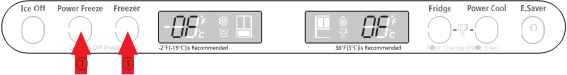
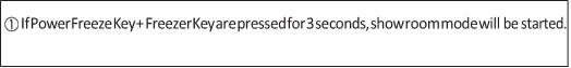
- If Power Freeze Key + Freezer Key are pressed simultaneously for 3 seconds during normal operation, show room mode will be started with buzzer sound(ding-dong).
- If above Power Freeze & Freezer Key are pressed one more time, show room mode will be canceled.
- If show room mode is selected, blinks “OF-OF” on the temperature setting display of the panel and it indicates the refrigerator has entered the show room mode.
- During show room mode, if fresh food and freezer compartments sensors are higher than 65 show room mode will be canceled automatically and freezing operation will be returned. (There is no buzzer sound when the show room mode is canceled by the temperature)
-
Operation contents of show room mode
- Display, Fan motor and etc operate normally, not to operate compressor only.
- Defrost is not operated. (including french heater)
- Display function of the initial real temperature is finished.
- Under the condition of show room mode, show room mode will be operated when Power On after Power OFF.
- Display, Fan motor and etc operate normally, not to operate compressor only.
4-1-6. Option setting function
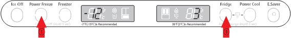
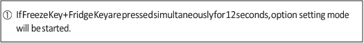
 If Freezer Key + Fridge Key are pressed simultaneously for 12 seconds during normal
operation, fresh food and freezer compartments temperature display will be changed to option
setting mode.


* Key control in option mode
|
Power Freeze Key |
Code Down key |
|
Freezer Key |
Code Up key |
|
Power Cool key |
Reference Value down key |
|
Fridge key |
Reference Value Up key |

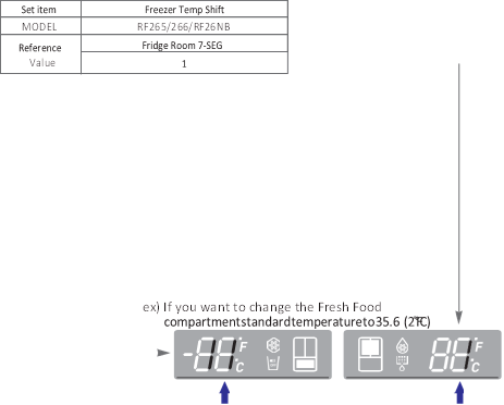
If the display changes to option setting mode, all displays will be off except freezer and fridge compartments temperature display as below.
(Fresh food and freezer compartments case will be explained only because all options are operated with the same method according to the option table.)


-
For example, if you want to change freezer compartment standard temperature to
 (- 2°C) by operating option, do as below.
This function is for changing the standard temperature.
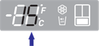
In
 (-19°C) of current temperature of freezer compartment, if you make the temperature lower to
  (-2°C) by the option, the standard temperature would be controlled
  (-21°C) Therefore, if you change the setting of temperature option to
  (-19°C) on the panel, the appliance will be operated with
  (-21°C).
 It means that standard temperature is controlled
  (-2°C) less than setting temperature in the display.
NOTE
-
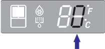
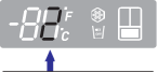
After changing to the option mode, fresh food compartment “0” , freezer compartment “0” will be displayed. ( Basically fresh food compartment “0”, freezer “0” would be set at shipping process, but setting value could be changed for the purpose of improving product at mass producing process.)
– If fresh food compartment “0” shows only, temperature reference value of freezer compartment will be set and current freezer compartment temperature code will be displayed on the freezer temperature display.
-
If freezer compartment “4” is set as below freezer compartment code after fresh food compartment “0 is set, standard temperature of freezer compartment will be lower than 28.4
 (-2.0°C).
 (Refer to the picture “changing the freezer compartment temperature”)

: If you wait for 20 seconds after completing the setting, MICOM will save the setting value to the EEPROM and normal display will be returned and the option setting mode will be canceled.
- Option changing method as above is the same as all RF266/265** model.
- Option changing method as above is the same as all RF266/265** model.
- By the same method as above, it is possible to control the fresh food compartment temperature, water supply, ice-maker harvest temperature/time, defrost return time, hysteresis by temperature, notch gap by temperature etc.
-
Option function is set in the EEPROM at shipping process in the factory. You would better not to change the option of your own.
Completing the setting is that option function return to normal display after 20 seconds. Do not turn off the appliance before returning to the normal display mode.

 NOTE
NOTE


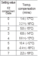
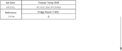 Temperature changing table of freezer compartment


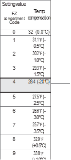 ex) If you want to change the freezer standard temperature to 28.4 (-2°C)


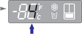
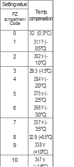
 Temperature changing table of fresh food compartment


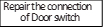
■Below options are applied to the applicable model with ice maker.
Do not set below options to the model without Ice Maker.
-
To change the ice maker harvest waiting time
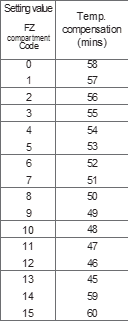 This option controls the harvest waiting time for ice dispensing from Ice maker
|
Set item |
ICE MAKER waiting time of ice making |
|
Reference Value |
Fridge Room 7-SEG |
|
3 |


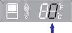
ex) If you want to change the waiting time to 60 minutes
- To change the ice making sensor temperature of ice maker
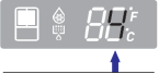
 This option Controls the standard temperature of judgment that is checking whether ice of ice maker is frozen completely or not.
|
Set item |
ICE MAKER control the temperature of ice making |
|
Reference Value |
Fridge Room 7-SEG |
|
4 |


ex) If you want to change the ice making sensor temperature to 5.0 (-15°C)


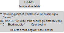
DATA1.Temperature table
Resistance value and MICOM port voltage of sensor according to the temperature SENSOR CHIP : based on PX41C
| ℃ |
℉ |
Voltage |
Resistance |
℃ |
℉ |
Voltage |
Resistance |
℃ |
℉ |
Voltage |
Resistance |
| -50 |
-58 |
4.694 |
153319 |
-5 |
23 |
3.107 |
16419 |
40 |
104 |
1.153 |
2997 |
| -49 |
-56.2 |
4.677 |
144794 |
-4 |
24.8 |
3.057 |
15731 |
41 |
105.8 |
1.124 |
2899 |
| -48 |
-54.4 |
4.659 |
136798 |
-3 |
26.6 |
3.006 |
15076 |
42 |
107.6 |
1.095 |
2805 |
| -47 |
-52.6 |
4.641 |
129294 |
-2 |
28.4 |
2.955 |
14452 |
43 |
109.4 |
1.068 |
2714 |
| -46 |
-50.8 |
4.622 |
122248 |
-1 |
30.2 |
2.904 |
13857 |
44 |
111.2 |
1.040 |
2627 |
| -45 |
-49 |
4.602 |
115631 |
0 |
32 |
2.853 |
13290 |
45 |
113 |
1.014 |
2543 |
| -44 |
-47.2 |
4.581 |
109413 |
1 |
33.8 |
2.802 |
12749 |
46 |
114.8 |
0.988 |
2462 |
| -43 |
-45.4 |
4.560 |
103569 |
2 |
35.6 |
2.751 |
12233 |
47 |
116.6 |
0.963 |
2384 |
| -42 |
-43.6 |
4.537 |
98073 |
3 |
37.4 |
2.700 |
11741 |
48 |
118.4 |
0.938 |
2309 |
| -41 |
-41.8 |
4.514 |
92903 |
4 |
39.2 |
2.649 |
11271 |
49 |
120.2 |
0.914 |
2237 |
| -40 |
-40 |
4.490 |
88037 |
5 |
41 |
2.599 |
10823 |
50 |
122 |
0.891 |
2167 |
| -39 |
-38.2 |
4.465 |
83456 |
6 |
42.8 |
2.548 |
10395 |
51 |
123.8 |
0.868 |
2100 |
| -38 |
-36.4 |
4.439 |
79142 |
7 |
44.6 |
2.498 |
9986 |
52 |
125.6 |
0.846 |
2036 |
| -37 |
-34.6 |
4.412 |
75077 |
8 |
46.4 |
2.449 |
9596 |
53 |
127.4 |
0.824 |
1973 |
| -36 |
-32.8 |
4.385 |
71246 |
9 |
48.2 |
2.399 |
9223 |
54 |
129.2 |
0.803 |
1913 |
| -35 |
-31 |
4.356 |
67634 |
10 |
50 |
2.350 |
8867 |
55 |
131 |
0.783 |
1855 |
| -34 |
-29.2 |
4.326 |
64227 |
11 |
51.8 |
2.301 |
8526 |
56 |
132.8 |
0.762 |
1799 |
| -33 |
-27.4 |
4.296 |
61012 |
12 |
53.6 |
2.253 |
8200 |
57 |
134.6 |
0.743 |
1745 |
| -32 |
-25.6 |
4.264 |
57977 |
13 |
55.4 |
2.205 |
7888 |
58 |
136.4 |
0.724 |
1693 |
| -31 |
-23.8 |
4.232 |
55112 |
14 |
57.2 |
2.158 |
7590 |
59 |
138.2 |
0.706 |
1642 |
| -30 |
-22 |
4.199 |
52406 |
15 |
59 |
2.111 |
7305 |
60 |
140 |
0.688 |
1594 |
| -29 |
-20.2 |
4.165 |
49848 |
16 |
60.8 |
2.064 |
7032 |
61 |
141.8 |
0.670 |
1547 |
| -28 |
-18.4 |
4.129 |
47431 |
17 |
62.6 |
2.019 |
6771 |
62 |
143.6 |
0.653 |
1502 |
| -27 |
-16.6 |
4.093 |
45146 |
18 |
64.4 |
1.974 |
6521 |
63 |
145.4 |
0.636 |
1458 |
| -26 |
-14.8 |
4.056 |
42984 |
19 |
66.2 |
1.929 |
6281 |
64 |
147.2 |
0.620 |
1416 |
| -25 |
-13 |
4.018 |
40938 |
20 |
68 |
1.885 |
6052 |
65 |
149 |
0.604 |
1375 |
| -24 |
-11.2 |
3.980 |
39002 |
21 |
69.8 |
1.842 |
5832 |
66 |
150.8 |
0.589 |
1335 |
| -23 |
-9.4 |
3.940 |
37169 |
22 |
71.6 |
1.799 |
5621 |
67 |
152.6 |
0.574 |
1297 |
| -22 |
-7.6 |
3.899 |
35433 |
23 |
73.4 |
1.757 |
5419 |
68 |
154.4 |
0.560 |
1260 |
| -21 |
-5.8 |
3.858 |
33788 |
24 |
75.2 |
1.716 |
5225 |
69 |
156.2 |
0.546 |
1225 |
| -20 |
-4 |
3.816 |
32230 |
25 |
77 |
1.675 |
5039 |
70 |
158 |
0.532 |
1190 |
| -19 |
-2.2 |
3.773 |
30752 |
26 |
78.8 |
1.636 |
4861 |
71 |
159.8 |
0.519 |
1157 |
| -18 |
-0.4 |
3.729 |
29350 |
27 |
80.6 |
1.596 |
4690 |
72 |
161.6 |
0.506 |
1125 |
| -17 |
1.4 |
3.685 |
28021 |
28 |
82.4 |
1.558 |
4526 |
73 |
163.4 |
0.493 |
1093 |
| -16 |
3.2 |
3.640 |
26760 |
29 |
84.2 |
1.520 |
4369 |
74 |
165.2 |
0.481 |
1063 |
| -15 |
5 |
3.594 |
25562 |
30 |
86 |
1.483 |
4218 |
75 |
167 |
0.469 |
1034 |
| -14 |
6.8 |
3.548 |
24425 |
31 |
87.8 |
1.447 |
4072 |
76 |
168.8 |
0.457 |
1006 |
| -13 |
8.6 |
3.501 |
23345 |
32 |
89.6 |
1.412 |
3933 |
77 |
170.6 |
0.446 |
978 |
| -12 |
10.4 |
3.453 |
22320 |
33 |
91.4 |
1.377 |
3799 |
78 |
172.4 |
0.435 |
952 |
| -11 |
12.2 |
3.405 |
21345 |
34 |
93.2 |
1.343 |
3670 |
79 |
174.2 |
0.424 |
926 |
| -10 |
14 |
3.356 |
20418 |
35 |
95 |
1.309 |
3547 |
80 |
176 |
0.414 |
902 |
| -9 |
15.8 |
3.307 |
19537 |
36 |
96.8 |
1.277 |
3428 |
81 |
177.8 |
0.404 |
877 |
| -8 |
17.6 |
3.258 |
18698 |
37 |
98.6 |
1.253 |
3344 |
82 |
179.6 |
0.394 |
854 |
| -7 |
19.4 |
3.208 |
17901 |
38 |
100.4 |
1.213 |
3204 |
83 |
181.4 |
0.384 |
832 |
| -6 |
21.2 |
3.158 |
17142 |
39 |
102.2 |
1.183 |
3098 |
84 |
183.2 |
0.375 |
810 |
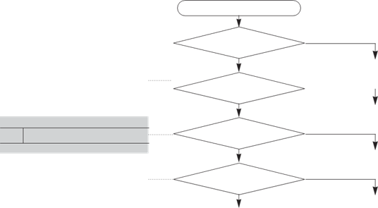
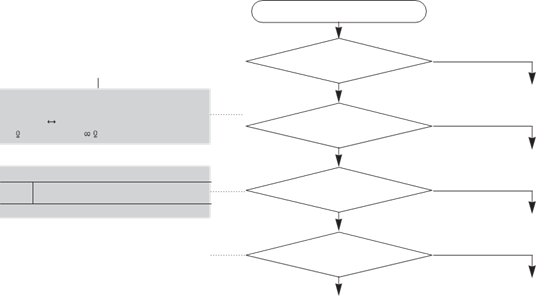
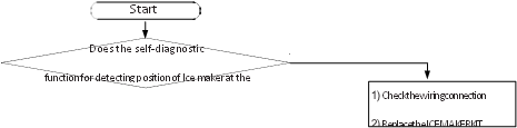
4-2-1. If the trouble is detected by self-diagnosis
- If ICE Maker Sensor has trouble

 ERROR Code
 Start
Start
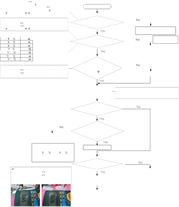
 Is MAIN PCB Connector CN90 inserted correctly?
YES
 Is ICE Maker Sensor
unit normal?
 YES
YES
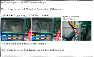
Is the voltage between
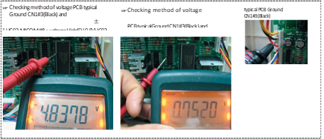
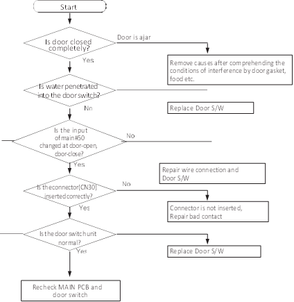
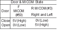
MAIN PCB Connector CN90#”4″(White) and CN1#”3″(Black) normal?
YES
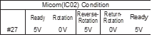
 Is input voltage of IC02 MICOM #30 normal?
 YES
YES
NO

N
O

NO(0.6V > Measurement < 4.6V)

NO
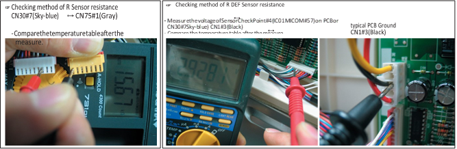
- If R Sensor has trouble

 ERROR Code

 Sensor MICOM/Connector number
Start
 Is MAIN PCB
Connector CN30 to CN75
correctly?
YES
Is R Sensor unit normal?
YES
Is the voltage between
 inserted
NO

NO

NO(0.6V > Measurement < 4.6V)
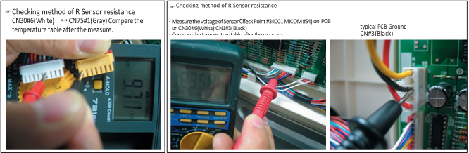
 Connector CN30#6(White) to CN1#3(Black) PCB typical Ground
 Voltage measured between 4.6V ~ 0.6V.
MAIN PCB Connector CN30#6(White) to CN1#3(Black) normal?
 YES
YES
Is the input voltage to NO IC01 MICOM #54 normal?
 YES
YES


Start
 Is MAIN PCB
Connector CN30 to CN75
correctly?
 YES
YES

 Is R DEF Sensor unit normal?
 YES
YES
NO
inserted

NO
 Sensor MICOM/Connector Number
 Connector CN30-“7″(Sky-blue) and CN1-“3″(Black) PCB common Ground
 Voltage measured between 4.6V ~ 0.6V.
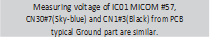
Is the input voltage between MAIN PCB Connector CN30#7(Skyblue)
to CN1#3(Black) normal?
YES
Is the input voltage of IC01 MICOM # 57 normal?
YES
NO(0.6V > Measurement < 4.6V)

NO

Start

 Sensor MICOM/Connector number
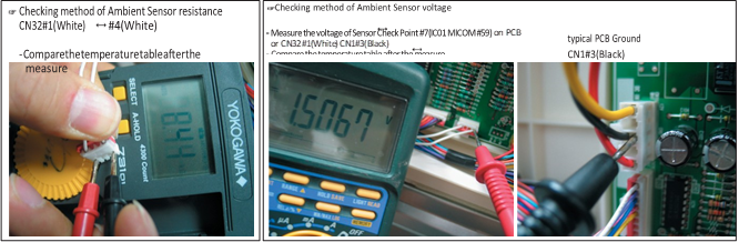
 Connector CN32#1(White) to CN1#3(Black) PCB typical Ground

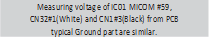 Voltage measured between 4.6V ~ 0.6V.
Is MAIN PCB
Connector CN32 inserted correctly?
YES
Is Ambient Sensor unit normal?
YES
Is the voltage between
MAIN PCB Connector CN32#1(White) to CN1#3(Black) normal?
YES
Is the input voltage of IC01 MICOM #59 normal?
YES
NO

NO

NO(0.6V > Measurement < 4.6V)

NO

Start

 Sensor MICOM/Connector number
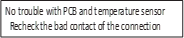
 Connector CN30#3(Red) to CN1#3(Black) PCB typical Ground
 Voltage measured between 4.6V ~ 0.6V.
Are MAIN PCB
Connector CN30 to CN75 inserted correctly?
YES
Is F Sensor unit normal?
YES
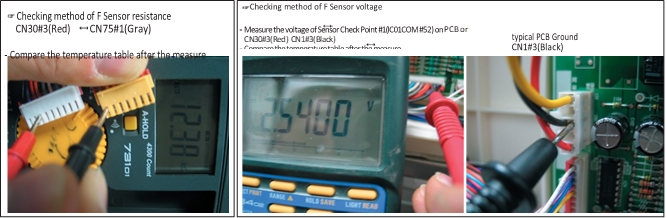
Is the voltage between
MAIN PCB Connector CN30#3(Red) to CN1#3(Black) normal?
YES
Is the input voltage of IC01 MICOM #52 normal?
YES
NO

NO

NO(0.6V > Measurement < 4.6V)

NO

Start


 Sensor MICOM/Connector number
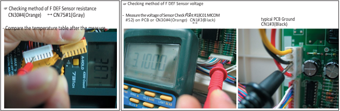
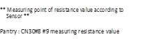
 Connector CN30#4(Orange) to CN1#3(Black) PCB typical Ground
 Voltage measured between 4.6V ~ 0.6V.
Are MAIN PCB
Connector CN30 to CN75 insert correctly?
YES
Is F DEF Sensor unit normal?
YES
Is the voltage between
MAIN PCB Connector CN30#4(Orange) to CN1#3(Black) normal?
YES
Is the input voltage of IC01 MICOM #53 normal?
YES
NO

NO

NO(0.6V > Measurement < 4.6V)

NO
- If Pantry Sensor has trouble

 ERROR Code

Start

 Sensor MICOM/Connector number
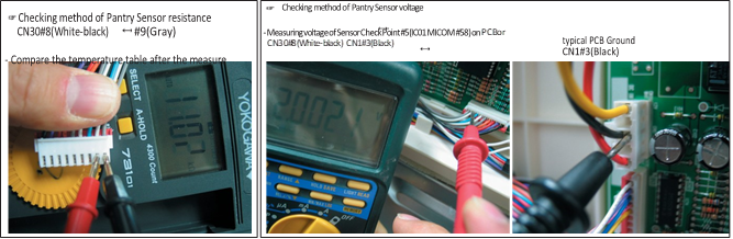
 Connector CN30#8(White-black) to CN1#3(Black) PCB typical Ground

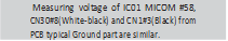 Voltage measured between 4.6V ~ 0.6V.
Is MAIN PCB
Connector CN30 insert correctly?
YES
Is Pantry Sensor normal?
YES
Is the voltage between
MAIN PCB Connector CN30#8(Whiteblack) to CN1#3(Black) normal?
YES
Is the input voltage of IC01 MICOM Pin# 58 normal?
YES
NO

NO

NO(0.6V > Measurement < 4.6V)

NO


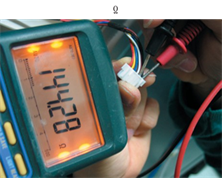
- If Pantry Room Damper Heater has trouble


 ERROR Code
|
MICOM #37 condition |
Initial power On |
Damper heater off |
Damper heater On |
|
4.0V ~ 4.5V |
4.0V ~ 4.5V |
0V |
4-2-2. If FAN does not operate
 Start
Start
Is COMP ON ?

 IsthevoltagebetweenMAIN PCBCN1#3(Black)andCN75#4(Sky
-blue)aroundDC7~12V?
IsthevoltagebetweenMAIN PCBCN1#3(Black)andCN75#3
(Orange)aroundDC7~12V?
Is the voltage between MAIN
PCB CN1#3 (Black) and CN75#2 (Yellow) around DC7~12V?

Is the voltage between MAIN PCB CN1#3 (Black) and CN30#2
(Purple) around 0V?
Is the voltage between MAIN PCB CN1#3 (Black) and CN30#1
 (Black) around 5V?
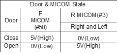
Door & MICOM State
Door
Close Open
F MICOM (#50)
5V(High) 0V(Low)
R MICOM(#3)
Right and Left 0V(Low)
5V(High)
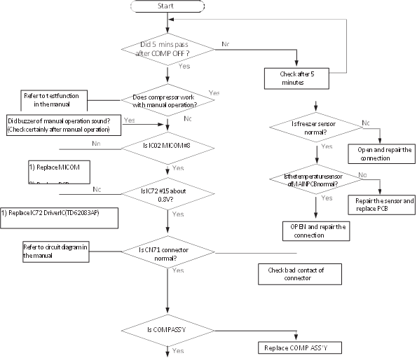
Power ON with 5 minutes delay after power OFF.
For preventing the over load of compressor)
In initial power to appliance, the compressor and fans of fresh food/ freezer, compressor fan operate. If freezer temperature is sensed of 41 by momentary power failure, fans will operate after 5 minutes.
DoesDC7~12Valternatewithbelow DC2VbetweenMAINPCBCN1#3(Black) andCN75#4(Sky-blue)
DoesDC7~12Valternatewithbelow DC2VbetweenMAINPCBCN1#3(Black) andCN75#3(Orange)
DoesDC7~12Valternatewith belowDC2VbetweenMAINPCB CN1#3(Black)andCN75-#2(Yellow)
Replace MAIN PCB
F FAN pulse voltage typical PCB Ground CN75#5(Black) CN10#3(Black)
The voltage measured around 2~3V with multi-meter though the voltage is
Reference
CN75-5(F),6(R),7(C)will generate the pulse signal when motor rotates. These signals will be inputted into MICOM.
Unless signals are not inputted during motor operating, will be ON 10 seconds after fan Off. But if signals are not still entered, the above operation will restart four times more.
If signals are not entered continuously, the motor will be restarted after 10 seconds.
This function is effective when the normal operation of motor would be restrained by foreign matters such as ice.
Expected causes
Check that if FAN-MOTOR has failure itself.
Check that if wiring connection has bad contact.
Check the input of the fan motor rotation pulse when motor fan operates.
very weak because of pulse signal
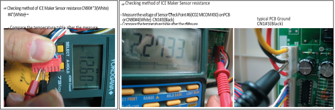
Display for checking the self-diagnostic function R FAN ERROR
Checking method of R,F,C FAN Motor voltage
The voltage between PCB typical Ground CN1-“3″(Black) and R FAN ; CN75#2(Yellow) shall be less than DC 7~12V.
F FAN ; CN75#3(Orange) shall be less than DC 7~12V. C FAN ; CN75#4(Sky-blue) shall be less than DC 7~12V.
– Recheck if resistance values are different after measuring.
typical PCB Ground
CN1#3(Black)
F FAN ERROR
1) R-FAN 2) F-FAN 3) C-FAN
C FAN ERROR
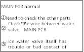
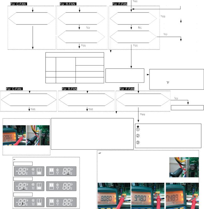
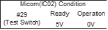
4-2-3. If ICE MAKER does not operate
Function ERROR Code


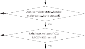


-
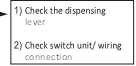
Check the wiring connection part
-
 Replace ICE MAKER KIT
-
 Replace the MAIN PCB
-
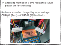
 1) Replace the Water Valve
* refer to operation condition of water valve


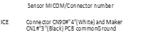
4-2-4. If defrost does not operate (F,R DEF Heater)

R DEF ERROR F DEF ERROR


 Start
Start
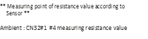
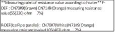
**Measuring point of resistance value according to sensor ** F-DEF : CN30#4 CN75#1 measuring resistance value
R-DEF : CN30#7 CN75#1 measuring resistance value
** 0 : Short trouble / : Open trouble
 Are the all deforst heater normal?


 Is defrost sensor by self-diagnostic normal?


 **Measuring point of resistance value according to sensor ** F-DEF : CN30#4 CN75#1 measuring resistance value
- EF : CN30#7 CN75#1 measuring resistance value
** 0V: Short trouble / 5V: Open trouble
Is the temperature of defrost sensor lower
 than 53.6 (12°C)?
 If Power Freeze Key + Fridge Key are pressed simultaneously for 8 seconds and then select any key, 3rd test mode(manual defrosting) will be operated.
Is power applied to each defrost heaters?
 Doesthesystemreturn tocoolingoperationafter heatingforspecifiedtime?
Reference
If defrost sensor temperatures of fresh food and freezer compartments are higher than 50 (10 ), 53.6 (12 ) by
the heating from heater, heating would be finished and will return to cooling operation after a pause.
Checking method of F,R DEF Heater resistance value F FEF ; CN70#9(Brown) CN71#9(Orange) R FEF ; CN70#7(White) CN71#9(Orange)
– Recheck if resistance values are different after the test
- F DEF Heater 2) R DEF Heater

 Isconnectionterminalof MAINPCBpartnormal?

4-2-5. If Power is not supplied
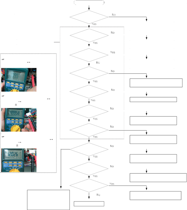
 Start
Start
Is plug connected in?

Is power 115(220)V both terminals of SMPS
 PCB CN1?
Checking method of SMPS voltage CN1 input ; CN1#1(Red) #3(Black) AC voltage
Is fuse on the SMPS PCB down?
 Is DC170(325)V applied both
terminals of BD1+,-
Is DC5.8V
- CheckPCBPATTERNandreplaceBD1
- ReplacePCBASS’Y
Checking method of SMPS 2nd output voltage CN2 input ; CN2#1(Red)
#3(Black) same as C19 terminals.. DC 5V 0.3V
applied between TOP switch 246Y C to S?
ReplacePCBASS’Y
Is 12V applied both terminals of C16?
Checking method of SMPS 2nd output voltage CN2 input ; CN2#5(Yellow)
#3(Black) same as C16 terminals. DC 12V 0.6V
Is 5V applied both terminals of C19?
- Replace U4 (D10LC20U)
- Replace PCB ASS’Y
- Replace REG1 (KA7805)
- Replace PCB ASS’Y
Does Panel PCB operate normally?
-
Checkassemblywireandrepair
- ReplacePanelPCB
Is normal load such as Relay?
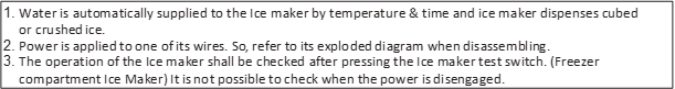
-CheckMAINPCBconnection
-Checktheconnections betweencabinettodoor
-Checktheconnections betweendoortopanelPCB
Is there any PCB soldering, short, breakage?
Normal(Recheck)
- Check the contact of lead wire
- Replace the applicable relay / PCB MAIN
- Solder again
- Replace PCB MAIN


4-2-6. If compressor does not operate

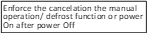
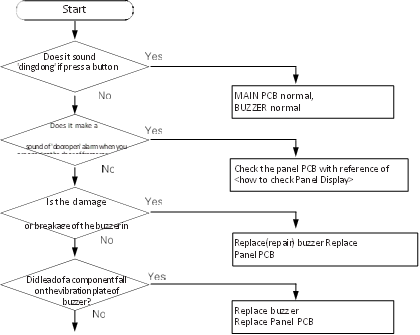
4-2-7. When alarm sound continuous without stop(related with buzzer sound)


If ‘ding-dong’ sounds continuously


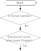

If ‘beep-beep’ sounds continuously


If buzzer does not sound
Buzzer is installed on the panel PCB in this model.
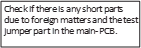
If buzzer does not sound when button is pressed, manual operation is started and door is opened, should separate panel PCB and check the breakage of buzzer and bad soldering.
It is very hard to repair the panel PCB because it consists of SMD assemblies.
 It is recommended to replace assembly PCB when the failure associated with panel is occurred except the minor error such as switch pressing error, surface peeling off and so on.


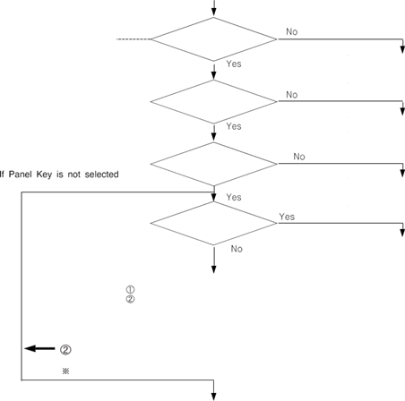
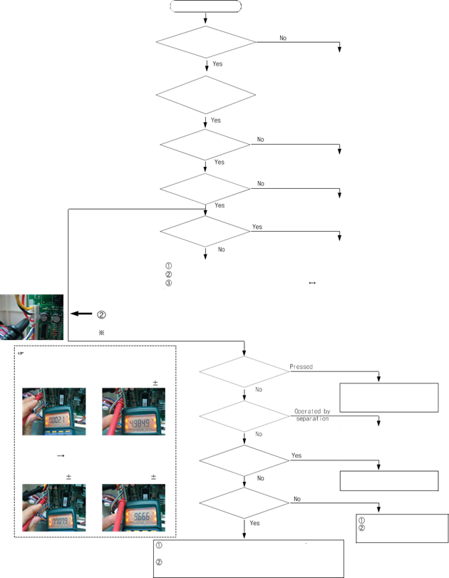
4-2-8. If Panel PCB does not work normally

When lighting of Panel PCB is disabled or only some LED Lamp are disabled


Is the connector of upper hinge cover inserted correctly?


 Is MAIN PCB

 connector (CN50) inserted correctly?
 Is Top Table Panel PCB connector


 inserted correctly?
Is lighting operate normally when replace Panel-PCB?


 If Panel PCB KEY is not selected


 If it is not repaired with using the basic checking method as above
4-2-9. If Pantry Panel PCB is not working normally

 Start
Start

 Does fresh food compartment door switch operate normally?
Is the connector of

 pantry room in fresh food compartment inserted


 correctly?

Is MAIN PCB
 Connector (CN78) inserted correctly?


If Panel Key is not selected
Is signal of MAIN PCB CN78 normal?


 Is the lighting operated when replace Pantry

 Panel-PCB?


 typical PCB Ground CN1#3(Black)
If Panel Panel PCB Key is not selected
If it is not repaired with using the basic checking method as above
Checking method of voltage Based on PCB typical Ground CN1#3(Black)
1) Key voltage ; CN78#1″(Purple)
- select(operating)(0V) 2)normal(about5.0V 0.5V)
- LED part voltage ; CN78-“7″(Yellow), “8”(Pink) Voltage of CN78 is same as IC74 #12,#11 voltage.
– Display On (0.7V 0.3V) – Display Off (9.7V 1V)
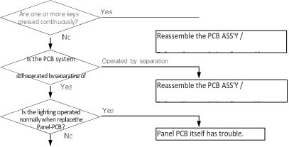
Is a key pressed continuously?
Is the PCB system
still operated by separating of the mechanism?
Is the lighting operated when replace Pantry Panel-PCB?
Is a normal voltage outputted from MAIN PCB IC74
in the key operating?
Reassemble PCB ASS’Y / Enforce the cancelation of pressed keys
Convertible compartment Panel PCB itself has trouble.
Replace MAIN PCB Check the short of MAIN Panel wire
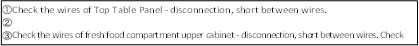
Check the wire of Pantry Room – disconnection, short between wires
Check the short/open of the pantry panel lighting circuit in MAIN PCB.


4-2-10. When refrigerator ROOM Lamp does not light up


The case of fresh food compartment(room) lamp will be explained only.
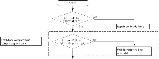


 Because it is possible to repair the other room lamps with the same method.


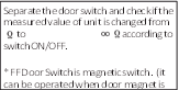
 Is the connection point of R-door switch


 normal?

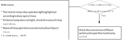


Reference
If the door is opened, the contact of door switch will be opened and MICOM will get applied 5V to finally sense Open.
If 5V has been sensed over two minutes afterwards, Door-Open alarm will sound  for 10 seconds in a oneminute cycle. For that reason, if the door switch has failure, the refrigerator can make
  Ding-Dong sound per a oneminute cycle. Please note the step for its service.


 When measure lamp resistance to the Wire Resistance can be changed by Lamp input voltage. (Actual measurement is below, it can be changed by performance)
 Fresh food compartment lamp CN70#1(Red)
  CN71#1 (Blue) ;
10(33)Ohm 3 Ohm Lamp ; 60W + 60W
 Freezer compartment lamp CN70#1(Red)
CN71#3 (Purple) ; 15(66)Ohm 5 Ohm Lamp ; 60W
 Checking method of Door Switch voltage
Measuring voltage of Sensor Check Point #5(IC01 MICOM #58) on PCB or CN30#8(White-black)  CN75#1(Gray)
Compare time table after measuring
Measuring voltage of CN30#8(white-black)  CN75#1(Gray) are below
typical PCB Ground CN10#3″(Black)


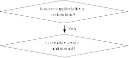
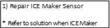
4-2-11. If ICE Water is not supplied


 typical PCB Ground CN1#3(Black)
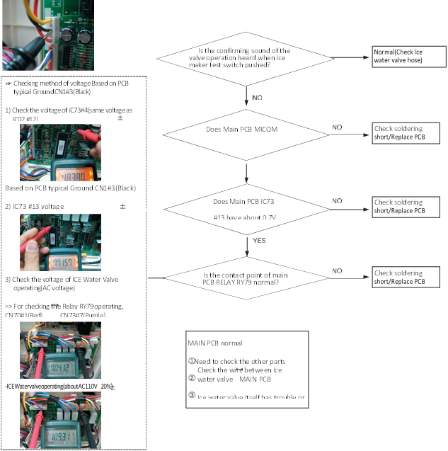


 4-2-12. If Water is not supplied

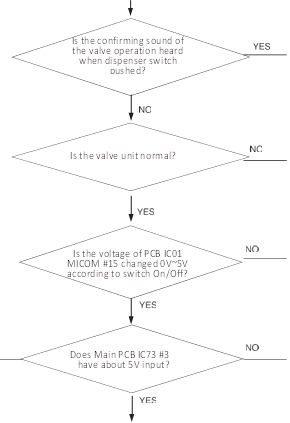
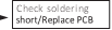
Does Main PCB IC73 #14 have about 0.7V output?
 Is the contact point of main PCB RELAY RY7A normal?