


![]()
![]()


For the latest product updates, visit us online at johnsoncontrols.com,
search commercial refrigeration

Refrigeration Products Catalog
Single-Stage Electromechanical Temperature Controls . . . . . . . . . . . . . . . . . . . R-17 Single-Stage Electronic Temperature Controls . . . . . . . . . . . . . . . . . . . . . . . . . R-44
Multi-Stage Electromechanical Temperature Controls . . . . . . . . . . . . . . . . . . . . R-59
Temperature Control Sensors and Accessories . . . . . . . . . . . . . . . . . . . . . . . . . R-79
Standard Electromechanical Pressure Controls . . . . . . . . . . . . . . . . . . . . . . . . . R-85
Single-Stage Electronic Pressure Controls . . . . . . . . . . . . . . . . . . . . . . . . . . . R-103 Electromechanical Lube Oil and Differential Pressure Controls . . . . . . . . . . . . R-105 Electronic Lube Oil and Differential Pressure Controls . . . . . . . . . . . . . . . . . . R-111 Pressure Sensors and Accessories . . . . . . . . . . . . . . . . . . . . . . . . . . . . . . . . . R-114
Single-Stage Electromechanical Temperature Controls . . . . . . R-17
A11 Series Low Temperature Cutout
Controls . . . . . . . . . . . . . . . . . . . . . . . . R-17
A19 Series Remote Bulb Control . . . . . . . . R-19 A19 Series High Range Temperature
Control . . . . . . . . . . . . . . . . . . . . . . . . . R-21
A19 Series Thermostat for Crop Drying. . R-22 A19 Series Hot Water Temperature Control
(Well Immersion) . . . . . . . . . . . . . . . . . R-23
A19 Temperature Control Less Enclosure (SPDT, Close Differential) . . . . . . . . . . R-24
A19 Series Thermostat for Hazardous Locations . . . . . . . . . . . . . . . . . . . . . R-25
Thermostat. . . . . . . . . . . . . . . . . . . . . . R-26
A19 Thermostat for Portable Heaters (Chain Mount and Drop Cord
Electrical Connection) . . . . . . . . . . . . . R-27 A19 Thermostat for Portable Cooling
Drop Cord Electrical Connection) . . . . R-28 A19 Series Automatic Changeover with
Strap-On Mounting. . . . . . . . . . . . . . . . R-29
Temperature Controls . . . . . . . . . . . . R-30 A19 Flange Mounted Duct Thermostat . . . R-31 A19 Series Fan or Cutout Control
(Liquid Expansion Bulb) . . . . . . . . . . . . R-32
A19 Temperature Control with Rainproof Enclosure . . . . . . . . . . . . . . . . . . . . . R-33
A19 Agricultural/Industrial Thermostat with NEMA 4X Enclosure . . . . . . . . . . . . . . R-34
A19 Temperature Control with NEMA 4X Enclosure (Remote Bulb). . . . . . . . . . R-36
A19 Water Chiller Control with Locked
Cut-Out/Adjustable Cut-In . . . . . . . . . . R-37 A19 Defrost Duration and Fan Delay
Control . . . . . . . . . . . . . . . . . . . . . . . . R-38
A25 Series Warm Air Limit Control with
Manual Reset . . . . . . . . . . . . . . . . . . . R-39
A70 Series Four-Wire, Two-Circuit
Temperature Control . . . . . . . . . . . . . R-40 A72 Series Two-Pole Heavy Duty
(Adjustable Differential) . . . . . . . . . . . . R-41 A72 Series Cooling Tower or Evaporative
Condenser Controls (Single-Stage
Outdoor Enclosure) . . . . . . . . . . . . . . . R-42 A72AA Coiled Bulb Space Thermostat
(Cooling) . . . . . . . . . . . . . . . . . . . . . . . R-43
Temperature Controls . . . . . . R-44
A421 Series Electronic Temperature
Controls . . . . . . . . . . . . . . . . . . . . . . . R-44
A421 Series Electronic Temperature
Controls with Integral Power Cord . . . R-47 A421 Series Electronic Temperature
Controls with Off-Cycle Defrost . . . . . R-50
A421 Series Electronic Temperature
Controls with Integral Cycle Timer . . . R-53 MR Series Defrost Control Modules . . . . . R-56 MR4PMUHV Electronic
Temperature/Defrost Control with
Relay Pack . . . . . . . . . . . . . . . . . . . . . R-58
Multi-Stage Electromechanical Temperature Controls . . . . . . R-59
A28 Series Two-Stage Temperature
Control. . . . . . . . . . . . . . . . . . . . . . . . . R-59
Two Stage Temperature Control . . . . . . . . R-59 A28 Series Two-Stage Flange Mounted
Duct Thermostat . . . . . . . . . . . . . . . . . R-61
A28 Two-Stage Industrial Thermostat (Watertight and Dusttight) . . . . . . . . . . R-62
A28 Two-Stage Temperature Control with Weatherproof Enclosure . . . . . . . . . . . R-63
Table of Contents
A28 Two-Stage Agricultural Thermostat with NEMA 4X Enclosure . . . . . . . . . . . . . . R-64
A36 Series Four-Stage Remote Bulb Thermostats . . . . . . . . . . . . . . . . . . . . . R-65
S26 Series Switching Subbase . . . . . . . . R-66 T22/T25/T26 Series Line Voltage Wall
Thermostat (Heating, Cooling, or
Heating and Cooling) . . . . . . . . . . . . R-67 Typical Wiring Diagram and Electrical
Ratings for Line Voltage Thermostats . R-69
T23 Series Fan Coil Thermostat
(with Fan and System Selectors) . . . . . R-70 T28 Series Fan Coil Thermostat (with or
without Fan Selector Switches) . . . . . . R-71
T46 Series Fan Coil Thermostat . . . . . . . R-72
Temperature Controls . . . . . . . R-74
MS Series Temperature Stage Control
Modules . . . . . . . . . . . . . . . . . . . . . . . . R-74
MS Series Single-Stage Control Modules
with Voltage Input . . . . . . . . . . . . . . . . R-76 MS4PMUHVT Multi-Stage Electronic
Temperature Control with Relay Pack . R-78
Temperature Control Sensors and Accessories . . . . . . . . . . . . . . . R-79
A99B Series Temperature Sensor . . . . . R-79 Bulb Wells . . . . . . . . . . . . . . . . . . . . . . . . . R-80
G Series Thermostat and Humidistat
Guards . . . . . . . . . . . . . . . . . . . . . . . . R-81 T22, T25, T26, T28, T46, and T91
Accessories . . . . . . . . . . . . . . . . . . . . . R-83
T91 Series Room Temperature Sensor . . . R-84
Pressure Controls . . . . . . . . . . R-85
P10 Series Low Pressure Control . . . . . . . R-85 P20 Series Air Conditioning/Pressure
Cutout Control . . . . . . . . . . . . . . . . . . . R-86
P29 Series Low Pressure Control with
Time Delay. . . . . . . . . . . . . . . . . . . . . . R-88
P47 Series Steam Pressure Limit Control. R-89 P67 Series Low Pressure Control . . . . . . R-90 P70, P72 Approximate Low Pressure
Settings for Typical Applications . . . . . R-91
P70, P72, and P170 Series Controls for
Low Pressure Applications . . . . . . . . . R-92 P70, P72, and P170 Series Controls for
High Pressure Applications . . . . . . . . . R-96
P70, P72, and P170 Series Controls for
Dual Pressure Applications . . . . . . . . R-100
Pressure Controls . . . . . . . . . R-103
P470 Electronic Pressure Control with
Display . . . . . . . . . . . . . . . . . . . . . . . R-103
Electromechanical Lube Oil and Differential Pressure
Controls . . . . . . . . . . . . . . . . . R-105
P28 Series Lube Oil Pressure Cutout
Control with Time Delay . . . . . . . . . . R-105 P32 Series Sensitive Pressure Switch . . R-106 P45 Series Lube Oil Pressure Cutout
Control with Time Delay . . . . . . . . . . R-107
P74 Series Differential Pressure Control. R-108 P128 and P145 Series Lube Oil Pressure
Controls . . . . . . . . . . . . . . . . . . . . . . . R-109
P12 Series Differential Pressure
Controls . . . . . . . . . . . . . . . . . . . . . . . R-110
Electronic Lube Oil and Differential Pressure
Controls . . . . . . . . . . . . . . . . . R-111
P545 Series Electronic Lube Oil Control . R-111 CST29A Adaptor Block for Carlyle®
Compressors . . . . . . . . . . . . . . . . . . . R-113
Accessories . . . . . . . . . . . . . . R-114
Replacement Timing Relays for P28 and
P29 Lube Oil Controls . . . . . . . . . . . R-114
Table of Contents
P100 Series Encapsulated Pressure
Switches. . . . . . . . . . . . . . . . . . . . . . . R-115
P499 Series Electronic Pressure
Transducers . . . . . . . . . . . . . . . . . . . R-119
R310A Series Current Sensing Switch . . R-122 Universal Mounting Brackets . . . . . . . . . . R-123 SEC99A UltraCap Armored Capillary . . . R-124
Refrigerant Sensors/Monitors . R-125
Detector . . . . . . . . . . . . . . . . . . . . . . . R-125
Accessories and Replacement Parts . R-126
Controls. . . . . . . . . . . . . . . . . R-127
F59 Series Sump Pump Switch . . . . . . . . R-127 F261 Series Fluid Flow Switches . . . . . . R-128 F262 Airflow Switch . . . . . . . . . . . . . . . . R-130
F263 Series Liquid Level Float
Switches. . . . . . . . . . . . . . . . . . . . . . . R-132
F61 and F62 Series Replacement
Paddles . . . . . . . . . . . . . . . . . . . . . . . R-134
F92 Series Air Volume Controls for
Shallow Wells . . . . . . . . . . . . . . . . . . R-135
F93 Series Air Volume Controls for
Deep Wells . . . . . . . . . . . . . . . . . . . . R-136
Motor Speed Controls . . . . . . . . R-137
P266 Series Single-Phase Condenser
Fan Speed Control . . . . . . . . . . . . . . R-137 P66/S66 Series Controls to P266 Series
Controls Replacement Guide . . . . . . R-140
VFD68 Variable Frequency Drives . . . . . R-142
Valves and Valve Accessories . R-145
V43/V243 Series Pressure-Actuated
Water-Regulating Valves . . . . . . . . . . R-145 V46 Series Pressure Actuated
Water-Regulating Valve . . . . . . . . . . . R-151
V46N Series Reverse Acting Valve . . . . . R-154
V46 Series Valve Sizing Information—90% Open Method. . . . . . . . . . . . . . . . . R-155
V46 Series Valve Dimensions . . . . . . . . . R-156 V47 Series Temperature Actuated
Modulating Valve. . . . . . . . . . . . . . . . R-157
V47N Series Reverse Acting Valve. . . . . R-159 V48 Series Three-Way Water
Regulating Valve . . . . . . . . . . . . . . . . R-160
V146 Series Two-Way Pressure-Actuated Water-Regulating Valves . . . . . . . . . R-161
V148 Series Three-Way Pressure-Actuated Water-Regulating Valves . . . . . . . . . R-166
V246 Series Two-Way Pressure-Actuated Water-Regulating Valves for
High-Pressure Refrigerants . . . . . . . R-171 V248 Series Three-Way Pressure-Actuated
High-Pressure Refrigerants . . . . . . . R-181 STT Water Valve Renewal Kit for
V46, V47, and V48 Series Valves . . . R-188
Companion Flanges and Gaskets for
V43, V46, and V47 Series Valves . . . R-189
Relays and Transformers . . . . . R-190
Y63, Y64, Y65, Y66, and Y69 Series
Transformers . . . . . . . . . . . . . . . . . . . R-190
System 450 Control Series . . . . R-192
System 450™ Series Modular Controls . R-192 System 450™ Series Control Module with
Network Communications . . . . . . . . R-203
System 450™ Reset Control Modules with
Real-Time Clock and Relay Output. . R-206 System 450™ Control Modules with
Analog Output . . . . . . . . . . . . . . . . . R-208
System 450™ Control Modules with
Relay Output . . . . . . . . . . . . . . . . . . R-210
System 450™ Control Module with
Hybrid Analog Output . . . . . . . . . . . . R-212 System 450™ Expansion Modules with
Analog Output . . . . . . . . . . . . . . . . . R-214
System 450™ Expansion Modules with
Relay Output . . . . . . . . . . . . . . . . . . R-216
Table of Contents
System 450™ Power Module . . . . . . . . . R-218 System 450™ Compatible Sensors,
Transducers, and Accessories . . . . . R-219
Cross-Reference . . . . . . . . . . . . . R-223
Ranco® Refrigeration Cross-Reference . R-223 ALCO® Cross Reference . . . . . . . . . . . . R-231
Numerics
210-604R . . . . . . . . . . . . . . . . . . . . . . . . . R-87
246-423 . . . . . . . . . . . . . . R-153, R-158, R-189
246-424 . . . . . . . . . . . . . . . . . . . . . . . . . . R-189
246-425 . . . . . . . . . . . . . . R-153, R-158, R-189
271-51 . . . . .R-88, R-107, R-109, R-112, R-123
426-424 . . . . . . . . . . . . . . . . . . . . R-153, R-158
A
A19AAB-10C . . . . . . . . . . . . . . . . . . . . . . . R-21
A19AAB-4C . . . . . . . . . . . . . . . . . . . . . . . . R-21
A19AAB-7C . . . . . . . . . . . . . . . . . . . . . . . . R-21
A19AAC-4C . . . . . . . . . . . . . . . . . . . . . . . R-19
A19AAC-9C . . . . . . . . . . . . . . . . . . . . . . . R-21
A19AAD-12C . . . . . . . . . . . . . . . . . . . . . . R-19
A19AAD-5C . . . . . . . . . . . . . . . . . . . . . . . R-19
A19AAE-3C . . . . . . . . . . . . . . . . . . . . . . . . R-22
A19AAF-12C . . . . . . . . . . . . . . . . . . . . . . . R-19
A19AAF-20C . . . . . . . . . . . . . . . . . . . . . . . R-19
A19AAF-21C . . . . . . . . . . . . . . . . . . . . . . . R-19
A19AAT-2C . . . . . . . . . . . . . . . . . . . . . . . . R-28
A19ABA-40C . . . . . . . . . . . . . . . . . . . . . . . R-19
A19ABB-2C . . . . . . . . . . . . . . . . . . . R-21, R-22
A19ABB-7C . . . . . . . . . . . . . . . . . . . . . . . . R-21
A19ABC-11C . . . . . . . . . . . . . . . . . . . . . . R-23
A19ABC-12C . . . . . . . . . . . . . . . . . . . . . . R-23
A19ABC-24C . . . . . . . . . . . . . . . . . . . . . . R-19
A19ABC-36C . . . . . . . . . . . . . . . . . . . . . . R-19
A19ABC-37C . . . . . . . . . . . . . . . . . . . . . . R-19
A19ABC-4C . . . . . . . . . . . . . . . . . . . . . . . R-19
A19ABC-74C . . . . . . . . . . . . . . . . . . . . . . R-19
A19ACA-14C . . . . . . . . . . . . . . . . . . . . . . R-19
A19ACA-15C . . . . . . . . . . . . . . . . . . . . . . R-19
A19ADB-1C . . . . . . . . . . . . . . . . . . . . . . . R-19
A19ADB-2C . . . . . . . . . . . . . . . . . . . . . . . R-23
A19ADN-1C . . . . . . . . . . . . . . . . . . . . . . . R-19
A19AGF-31C . . . . . . . . . . . . . . . . . . . . . . R-24
A19ANC-1C . . . . . . . . . . . . . . . . . . . . . . . R-33
A19AUC-1C . . . . . . . . . . . . . . . . . . . . . . . R-25
A19AUC-2C . . . . . . . . . . . . . . . . . . . . . . . R-25
A19AUC-3C . . . . . . . . . . . . . . . . . . . . . . . R-25
A19AUC-4C . . . . . . . . . . . . . . . . . . . . . . . R-25
A19BAB-3C . . . . . . . . . . . . . . . . . . . . . . . . R-26
A19BAC-1C . . . . . . . . . . . . . . . . . . . . . . . R-26
A19BAF-1C . . . . . . . . . . . . . . . . . . . . . . . . R-26
A19BAG-1C . . . . . . . . . . . . . . . . . . . . . . . R-27
A19BBC-2C . . . . . . . . . . . . . . . . . . . . . . . R-26
A19BUC-2C . . . . . . . . . . . . . . . . . . . . . . . R-25
A19CAC-1C . . . . . . . . . . . . . . . . . . . . . . . R-29
A19CAC-2C . . . . . . . . . . . . . . . . . . . . . . . R-29
A19DAC-10C . . . . . . . . . . . . . . . . . . . . . . R-30
A19DAC-12C . . . . . . . . . . . . . . . . . . . . . . R-30
A19DAC-1C . . . . . . . . . . . . . . . . . . . . . . . R-30
A19DAC-9C . . . . . . . . . . . . . . . . . . . . . . . R-30
A19DAF-2C . . . . . . . . . . . . . . . . . . . . . . . R-30
A19EAF-1C . . . . . . . . . . . . . . . . . . . . . . . R-31
A19EAF-2C . . . . . . . . . . . . . . . . . . . . . . . R-31
A19EBA-1C . . . . . . . . . . . . . . . . . . . . . . . R-32
A19EBB-1C . . . . . . . . . . . . . . . . . . . . . . . R-32
A19EBC-1C . . . . . . . . . . . . . . . . . . . . . . . R-32
A19EDB-1C . . . . . . . . . . . . . . . . . . . . . . . R-32
A19KNC-1C . . . . . . . . . . . . . . . . . . . . . . . R-35
A19PRC-1C . . . . . . . . . . . . . . . . . . . . . . . R-34
A19QSC-1C . . . . . . . . . . . . . . . . . . . . . . . R-36
A19QSC-2C . . . . . . . . . . . . . . . . . . . . . . . R-36
A19QSC-3C . . . . . . . . . . . . . . . . . . . . . . . R-36
A19QSC-4C . . . . . . . . . . . . . . . . . . . . . . . R-36
A19ZBA-1C . . . . . . . . . . . . . . . . . . . . . . . R-37
A19ZBC-2C . . . . . . . . . . . . . . . . . . . . . . . R-38
A25AN-1C . . . . . . . . . . . . . . . . . . . . . . . . R-39
A25AP-1C . . . . . . . . . . . . . . . . . . . . . . . . R-39
A25CN-1C . . . . . . . . . . . . . . . . . . . . . . . . R-39
A25CP-1C . . . . . . . . . . . . . . . . . . . . . . . . R-39
A28AA-28C . . . . . . . . . . . . . . . . . . . . . . . R-59
A28AA-29C . . . . . . . . . . . . . . . . . . . . . . . R-59
A28AA-36C . . . . . . . . . . . . . . . . . . . . . . . R-59
A28AA-37C . . . . . . . . . . . . . . . . . . . . . . . R-59
A28AA-4C . . . . . . . . . . . . . . . . . . . . . . . . R-59
A28AA-9C . . . . . . . . . . . . . . . . . . . . . . . . R-59
A28AB-1C . . . . . . . . . . . . . . . . . . . . . . . . R-59
A28AJ-4C . . . . . . . . . . . . . . . . . . . . . . . . . R-59
A28AK-1C . . . . . . . . . . . . . . . . . . . . . . . . R-61
A28AK-2C . . . . . . . . . . . . . . . . . . . . . . . . R-61
A28KA-1C . . . . . . . . . . . . . . . . . . . . . . . . R-62
A28MA-1C . . . . . . . . . . . . . . . . . . . . . . . . R-63
A28MA-2C . . . . . . . . . . . . . . . . . . . . . . . . R-63
A28PA-2C . . . . . . . . . . . . . . . . . . . . . . . . R-64
A28PJ-1C . . . . . . . . . . . . . . . . . . . . . . . . . R-64
A36AHA-50C . . . . . . . . . . . . . . . . . . . . . . R-65
A36AHA-52C . . . . . . . . . . . . . . . . . . . . . . R-65
A36AHA-58C . . . . . . . . . . . . . . . . . . . . . . R-65
A36AHB-33C . . . . . . . . . . . . . . . . . . . . . . R-65
A421ABC-02C . . . . . . . . . . . . . . . . . . . . . R-45
Note: Page numbers in italics denote pages where the product code number appears, but not as the main part.
Code Number Index
A421ABC-03C . . . . . . . . . . . . . . . . . . . . . R-45
A421ABC-04C . . . . . . . . . . . . . . . . . . . . . R-45
A421ABC-06C . . . . . . . . . . . . . . . . . . . . . R-45
A421ABD-02C . . . . . . . . . . . . . . . . . . . . . R-51
A421ABG-02C . . . . . . . . . . . . . . . . . . . . . R-48
A421ABJ-02C . . . . . . . . . . . . . . . . . . . . . . R-48
A421ABT-02C . . . . . . . . . . . . . . . . . . . . . . R-54
A421AEC-01C . . . . . . . . . . . . . . . . . . . . . R-45
A421AEC-02C . . . . . . . . . . . . . . . . . . . . . R-45
A421AED-01C . . . . . . . . . . . . . . . . . . . . . R-51
A421AED-02C . . . . . . . . . . . . . . . . . . . . . R-51
A421AEJ-01C . . . . . . . . . . . . . . . . . . . . . . R-48
A421AET-01C . . . . . . . . . . . . . . . . . . . . . . R-54
A421GBF-02C . . . . . . . . . . . . . . . . . . . . . R-45
A421GEF-01C . . . . . . . . . . . . . . . . . . . . . R-45
A421GEF-02C . . . . . . . . . . . . . . . . . . . . . R-45
A70GA-1C . . . . . . . . . . . . . . . . . . . . . . . . . R-40
A70GA-2C . . . . . . . . . . . . . . . . . . . . . . . . . R-40
A70HA-14C . . . . . . . . . . . . . . . . . . . . . . . . R-40
A70HA-1C . . . . . . . . . . . . . . . . . . . . . . . . . R-40
A70HA-2C . . . . . . . . . . . . . . . . . . . . . . . . . R-40
A70KA-1C . . . . . . . . . . . . . . . . . . . . . . . . . R-40
A72AA-1C . . . . . . . . . . . . . . . . . . . . . . . . . R-41
A72AA-2C . . . . . . . . . . . . . . . . . . . . . . . . . R-41
A72AA-3C . . . . . . . . . . . . . . . . . . . . . . . . . R-41
A72AA-4C . . . . . . . . . . . . . . . . . . . . . . . . . R-43
A72AE-1C . . . . . . . . . . . . . . . . . . . . . . . . . R-42
A72AP-1C . . . . . . . . . . . . . . . . . . . . . . . . . R-41
A72CE-1C . . . . . . . . . . . . . . . . . . . . . . . . . R-42 A99BA-200C . . . . . . R-74, R-79, R-195, R-220 A99BB-200C . . . . . . . . . . . . . R-58, R-74, R-78,
. . . . . . . . . . . . . . . . . . . . R-79, R-195, R-220
A99BB-25C . . . . . . . . . . . . R-79, R-195, R-220
A99BB-300C . . . . . . R-74, R-79, R-195, R-220
A99BB-500C . . . . . . R-74, R-79, R-195, R-220
A99BB-600C . . . . . . R-74, R-79, R-195, R-220
A99BC-1500C . . . . . . . . . . R-79, R-195, R-220
A99BC-25C . . . . . . . . . . . . R-79, R-195, R-220
A99BC-300C . . . . . . . . . . . R-79, R-195, R-220
A99BC-500C . . . . . . . . . . . . . . . . . . . . . . . R-79
A99-CLP-1 . . . . . . . . . . . . R-79, R-196, R-220
ADP11A-600R . . . . . . . . . R-79, R-196, R-220
B
BKT16A-600R . . . . . . . . . . . . . . . . . . . . . . R-85
BKT182-1R . . . . . . . . . . . . . . . . . . . . . . . R-106
BKT229-1R . . . . . . . . . . . . . . . . . . . . . . . R-106
BKT287-1R . . . . . . . . . . . R-195, R-204, R-207,
. . . . . . . . . . . . . . . . . . . R-208, R-210, R-213,
. . . . . . . . . . . . . . . . . . . . R-214, R-216, R-218
BKT287-2R . . . . . . . . . . . R-195, R-204, R-207,
. . . . . . . . . . . . . . . . . . . R-208, R-210, R-213,
. . . . . . . . . . . . . . . . . . . . R-214, R-216, R-218
BKT287-3R . . . . . . . . . . . R-195, R-204, R-207,
. . . . . . . . . . . . . . . . . . . R-208, R-210, R-213,
. . . . . . . . . . . . . . . . . . . . R-214, R-216, R-218
BKT287-4R . . . . . . . . . . . R-195, R-204, R-207,
. . . . . . . . . . . . . . . . . . . R-208, R-210, R-213,
. . . . . . . . . . . . . . . . . . . . R-214, R-216, R-218 BKT38A-600R . . . . . . . . . R-107, R-109, R-123 BKT38A-601R . . . . . . . . . . . . . . . . . . . . R-109
BKT48A-600R . . . . . . . . . . . . . . . . . . . . . R-72
BOX10A-600R . . . . . . . . . . R-79, R-195, R-220
C
C450CBN-3C . . . . . . . . . . . . . . . .R-195, R-210
C450CCN-3C . . . . . . . . . . . . . . . .R-195, R-210
C450CEN-1C . . . . . . . . . . . . . . . .R-195, R-204
C450CPN-3C . . . . . . . . . . . . . . . .R-195, R-208
C450CPW-100C . . . . . . . . . . . . . .R-195, R-213
C450CQN-3C . . . . . . . . . . . . . . . .R-195, R-208
C450CRN-1C . . . . . . . . . . . . . . . .R-195, R-204
C450RBN-3C . . . . . . . . . . . . . . . .R-195, R-207
C450RCN-3C . . . . . . . . . . . . . . . .R-195, R-207
C450SBN-3C . . . . . . . . . . . . . . . .R-195, R-216
C450SCN-3C . . . . . . . . . . . . . . . .R-195, R-216
C450SPN-1C . . . . . . . . . . . . . . . .R-195, R-214
C450SQN-1C . . . . . . . . . . . . . . . .R-195, R-214
C450YNN-1C . . . . . . . . . . . . . . . .R-195, R-218
CSE57A-600 . . . . . . . . . . . . . . . . . . . . . . R-65
CST29A-600C . . . . . . . . . . . . . . . . . . . . R-113
CVR17A-620R . . . . . . . . . . . . R-40, R-41, R-43
CVR17A-621R . . . . . . . . . . . . . . . . .R-40, R-41
CVR28A-617R . . . . . . R-20, R-21, R-23, R-24,
. . . . . . . . . . . . . . . . . . . . . . . R-26, R-29, R-60
CVR28A-618R . . . . . . R-20, R-21, R-23, R-24,
. . . . . . . . . . . . . . . . . . R-26, R-31, R-32, R-60
CVR61A-600R . . . . . . . . . . . . . . . . . . . . . R-37
CVR88A-600R . . . . . . . . . . . . . . . . . . . . . R-72
Code Number Index
D
DBK10A-600R . . . . . . . . . . . . . . . . . . . . R-147
DBK10A-601R . . . . . . . . . . . . . . R-147, R-148
DBK10A-602R . . . . . . . . . . . . . . . . . . . . R-147
DBK10A-603R . . . . . . . . . . . . . . . . . . . . R-147
DBK11A-600R . . . . . . . . . . . . . . . . . . . . R-147
DBK11A-601R . . . . . . . . . . . . . . . . . . . . R-147
DBK11A-602R . . . . . . . . . . . . . . . . . . . . R-147
DBK11A-603R . . . . . . . . . . . . . . . . . . . . R-147
DPM17A-600R . . . . . . . . . . . . . . . . . . . . R-188
DPM17A-601R . . . . . . . . . . . . . . . . . . . . R-188
DPM18A-600R . . . . . . . . . . . . . . . . . . . . R-147
DPM18A-601R . . . . . . . . . . . . . . . . . . . . R-147
DPM18A-602R . . . . . . . . . . . . . . . . . . . . R-147
DPM18A-603R . . . . . . . . . . . . . . . . . . . . R-147
DPT2650-005D-AB . . . . . . . . . . . R-196, R-221
DPT2650-0R5D-AB . . . . . . . . . . R-196, R-221
DPT2650-10D-AB . . . . . . . . . . . . R-196, R-221
DPT2650-2R5D-AB . . . . . . . . . . R-196, R-221
DPT2650-R25B-AB . . . . . . . . . . . R-196, R-221
DSC16A-600R . . . . . . . . . . . . . . . . . . . . R-147
DSC16A-601R . . . . . . . . . . . . . . . . . . . . R-147
DSC16A-602R . . . . . . . . . . . . . . R-147, R-148
DSC16A-603R . . . . . . . . . . . . . . . . . . . . R-147
F
F261KAH-V01C . . . . . . . . . . . . . . . . . . . R-128
F261KEH-V01C . . . . . . . . . . . . . . . . . . . R-128
F261KFH-V01C . . . . . . . . . . . . . . . . . . . R-128
F261KFH-V02C . . . . . . . . . . . . . . . . . . . R-128
F261MAH-V01C . . . . . . . . . . . . . . . . . . . R-128
F261MAL-V01C . . . . . . . . . . . . . . . . . . . R-128
F261MEH-V01C . . . . . . . . . . . . . . . . . . . R-128
F261MFH-V01C . . . . . . . . . . . . . . . . . . . R-128
F262KDH-01C . . . . . . . . . . . . . . . . . . . . R-130
F263MAC-V01C . . . . . . . . . . . . . . . . . . . R-132
F263MAP-V01C . . . . . . . . . . . . . . . . . . . R-132
F59A-1C . . . . . . . . . . . . . . . . . . . . . . . . . R-127
F59A-2C . . . . . . . . . . . . . . . . . . . . . . . . . R-127
F59H-1C . . . . . . . . . . . . . . . . . . . . . . . . . R-127
FLG15A-600 . . . . . . . . . . . . . . . . . . . . . . R-189
FLG15A-601 . . . . . . . . . . . . . . . . . . . . . . R-189
FTG13A-600R . . . . . . . . . . . . R-20, R-21, R-37,
. . . . . . . . . . . . . . . . . . . . . . R-41, R-59, R-80
FTG18A-600R . . . . . . . . . . . . . . . . . . . . . R-106
G
GRD10-1R . . . . . . . . . . . . . . . . . . . . . . . . R-81
GRD10A-600 . . . . . . . . . . . . . . . . . . . . . . R-81
GRD10A-601 . . . . . . . . . . . . . . . . . . . . . . R-81
GRD10A-606 . . . . . . . . . . . . . . . . . . . . . . R-81
GRD10A-608 . . . . . . . . . . . . . . . . . . . . . . R-81
GRD10A-609 . . . . . . . . . . . . . . . . . . . . . . R-81
H
HE-6300 . . . . . . . . . . . . . . . . . . . . . . . . . . R-76
HE-6310 . . . . . . . . . . . . . . . . . . . . . . . . . . R-76
HE-67S3-0N00P . . . . . . . . . . . . . .R-196, R-221
HE-67S3-0N0BT . . . . . . . . . . . . .R-196, R-221
HE-68N2-0N00WS . . . . . . . . . . . .R-196, R-221
HE-68N3-0N00WS . . . . . . . . . . . .R-196, R-221
K
KEY12A-600 . . . . . . . . . . . . . . . . . . . . . . . R-81
KIT14A-612 . . . . . . . . . . . R-153, R-158, R-189
KIT14A-613 . . . . . . . . . . . R-153, R-158, R-189
KIT14A-614 . . . . . R-146, R-153, R-158, R-189 KIT21A-600 . . . . . . . . . . . . . . . . . . . . . . R-134
KIT21A-601 . . . . . . . . . . . . . . . . . . . . . . R-134
KITP545-82C . . . . . . . . . . . . . . . .R-112, R-113
KNB17A-600R . . . . . . . . . . . . . . . . . . . . . R-83
KNB20A-600R . . . . . . . . . . . . . . . . . . . . . R-83
KNB20A-602R . . . . . . . . . . . R-20, R-21, R-23,
. . . . . . . . . . . . . . . . . . . . . . . R-24, R-26, R-60
KNB26A-600R . . . . . . . . . . . . . . . . .R-72, R-83
M
MR1DR24-11C . . . . . . . . . . . . . . . . . . . . . R-56
MR2DR24-11C . . . . . . . . . . . . . . . . . . . . . R-56
MR2PM24-11C . . . . . . . . . . . . . . . . . . . . . R-56
MR4DR24-12C . . . . . . . . . . . . . . . . . . . . . R-56
MR4PM12C-12C . . . . . . . . . . . . . . . . . . . R-58
MR4PM24-12C . . . . . . . . . . . . . . . . . . . . . R-56
MR4PMUHV-12C . . . . . . . . . . . . . . . . . . . R-58
MS1DR24T-11C . . . . . . . . . . . . . . . . . . . . R-74
MS1DR24V-11C . . . . . . . . . . . . . . . . . . . . R-76
MS2DR24T-11C . . . . . . . . . . . . . . . . . . . . R-74
MS2PM24T-11C . . . . . . . . . . . . . . . . . . . . R-74
MS4DR24T-11C . . . . . . . . . . . . . . . . . . . . R-74
MS4PM12CT-11C . . . . . . . . . . . . . . . . . . R-78
Code Number Index
MS4PM24T-11C . . . . . . . . . . . . . . . . . . . . R-74
MS4PMUHVT-11C . . . . . . . . . . . . . . . . . . R-78
P
P10BC-7C . . . . . . . . . . . . . . . . . . . . . . . . . R-85
P10BG-3C . . . . . . . . . . . . . . . . . . . . . . . . . R-85
P10BJ-1C . . . . . . . . . . . . . . . . . . . . . . . . . R-85
P10FC-4C . . . . . . . . . . . . . . . . . . . . . . . . . R-85
P10PA-11C . . . . . . . . . . . . . . . . . . . . . . . . R-85
P128AA-17C . . . . . . . . . . . . . . . . . . . . . . R-109
P128AA-1C . . . . . . . . . . . . . . . . . . . . . . . R-109
P128AA-2C . . . . . . . . . . . . . . . . . . . . . . . R-109
P12AA-1C . . . . . . . . . . . . . . . . . . . . . . . . R-110 P145NCA-12C . . . . . . . . . . . . . . R-107, R-109
P145NCA-82C . . . . . . . . . . . . . . R-107, R-109
P145NCB-12C . . . . . . . . . . . . . . R-107, R-109
P145NCB-82C . . . . . . . . . . . . . . R-107, R-109
P170AA-118C . . . . . . . . . . . . . . . . . . . . . . R-96
P170AA-2C . . . . . . . . . . . . . . . . . . . . . . . . R-97
P170AA-400C . . . . . . . . . . . . . . . . . . . . . . R-97
P170AB-12C . . . . . . . . . . . . . . . . . . . . . . . R-93
P170AB-2C . . . . . . . . . . . . . . . . . . . . . . . . R-93
P170CA-1C . . . . . . . . . . . . . . . . . . . . . . . . R-93
P170CA-3C . . . . . . . . . . . . . . . . . . . . . . . . R-96
P170CA-400C . . . . . . . . . . . . . . . . . . . . . . R-97
P170DA-1C . . . . . . . . . . . . . . . . . . . . . . . . R-96
P170DA-400C . . . . . . . . . . . . . . . . . . . . . . R-97
P170EA-14C . . . . . . . . . . . . . . . . . . . . . . . R-93
P170KA-1C . . . . . . . . . . . . . . . . . . . . . . . . R-96
P170LB-1C . . . . . . . . . . . . . . . . . . . . . . . R-101
P170LB-6C . . . . . . . . . . . . . . . . . . . . . . . R-100
P170MA-18C . . . . . . . . . . . . . . . . . . . . . R-100
P170MA-1C . . . . . . . . . . . . . . . . . . . . . . R-101
P170NA-1C . . . . . . . . . . . . . . . . . . . . . . . R-101
P170SA-1C . . . . . . . . . . . . . . . . . . . . . . . R-100
P20BB-1C . . . . . . . . . . . . . . . . . . . . . . . . . R-86
P20DB-1C . . . . . . . . . . . . . . . . . . . . . . . . . R-86
P20EB-18C . . . . . . . . . . . . . . . . . . . . . . . . R-86
P20EB-1C . . . . . . . . . . . . . . . . . . . . . . . . . R-86
P20EB-2C . . . . . . . . . . . . . . . . . . . . . . . . . R-86
P20GB-1C . . . . . . . . . . . . . . . . . . . . . . . . . R-86
P28AA-17C . . . . . . . . . . . . . . . . . . . . . . . R-105
P28AA-18C . . . . . . . . . . . . . . . . . . . . . . . R-105
P28AA-1C . . . . . . . . . . . . . . . . . . . . . . . . R-105
P28AA-2C . . . . . . . . . . . . . . . . . . . . . . . . R-105
P28AN-1C . . . . . . . . . . . . . . . . . . . . . . . . R-105
P28DA-1C . . . . . . . . . . . . . . . . . . . . . . . R-105
P28DN-1C . . . . . . . . . . . . . . . . . . . . . . . R-105
P28GA-2C . . . . . . . . . . . . . . . . . . . . . . . R-105
P28NA-5C . . . . . . . . . . . . . . . . . . . . . . . R-105
P29NC-2C . . . . . . . . . . . . . . . . . . . . . . . . R-88
P29NC-3C . . . . . . . . . . . . . . . . . . . . . . . . R-88
P29NC-49C . . . . . . . . . . . . . . . . . . . . . . . R-88
P29NC-53C . . . . . . . . . . . . . . . . . . . . . . . R-88
P29NF-1C . . . . . . . . . . . . . . . . . . . . . . . . R-88
P32AC-1C . . . . . . . . . . . . . . . . . . . . . . . R-106
P32AC-2C . . . . . . . . . . . . . . . . . . . . . . . R-106
P32AF-1C . . . . . . . . . . . . . . . . . . . . . . . . R-106
P32AF-2C . . . . . . . . . . . . . . . . . . . . . . . . R-106
P400AD-1C . . . . . . . . . . . . . . . . .R-112, R-113
P400AD-2C . . . . . . . . . . . . . . . . . . . . . . R-112
P400BD-1C . . . . . . . . . . . . . . . . . . . . . . R-112
P45NAA-10C . . . . . . . . . . . . . . . . . . . . . R-107
P45NAA-5C . . . . . . . . . . . . . . . . . . . . . . R-107
P45NCA-12C . . . . . . . . . . . . . . . . . . . . . R-107
P45NCA-82C . . . . . . . . . . . . . . . . . . . . . R-107
P47AA-13C . . . . . . . . . . . . . . . . . . . . . . . R-89
P47AA-1C . . . . . . . . . . . . . . . . . . . . . . . . R-89
P47AA-4C . . . . . . . . . . . . . . . . . . . . . . . . R-89
P47AB-3C . . . . . . . . . . . . . . . . . . . . . . . . R-89
P47BA-1C . . . . . . . . . . . . . . . . . . . . . . . . R-89
P47BA-6C . . . . . . . . . . . . . . . . . . . . . . . . R-89
P47EA-1C . . . . . . . . . . . . . . . . . . . . . . . . R-89
P47GA-9C . . . . . . . . . . . . . . . . . . . . . . . . R-89 P499RAP-101C . . . . . . . . . . . . . .R-197, R-222
P499RAP-101K . . . . . . . . . . . . . .R-197, R-222
P499RAP-102C . . . . . . . . . . . . . .R-197, R-222
P499RAP-105C . . . . . . . . . . . . . .R-197, R-222
P499RAP-105K . . . . . . . . . . . . . .R-197, R-222
P499RAP-107C . . . . . . . . . . . . . .R-197, R-222
P499RAP-107K . . . . . . . . . . . . . .R-197, R-222
P499RAPS100C . . . . . . . . . . . . . .R-197, R-222
P499RAPS100K . . . . . . . . . . . . . .R-197, R-222
P499RAPS102C . . . . . . . . . . . . . .R-197, R-222
P499RAPS102K . . . . . . . . . . . . . .R-197, R-222
P499RCP-101C . . . . . . . . . . . . . .R-197, R-221
P499RCP-101K . . . . . . . . . . . . . .R-197, R-221
P499RCP-105C . . . . . . . . . . . . . .R-197, R-221
P499RCP-105K . . . . . . . . . . . . . .R-197, R-221
P499RCP-107C . . . . . . . . . . . . . .R-197, R-221
P499RCP-107K . . . . . . . . . . . . . .R-197, R-221
P499RCP-401C . . . . . . . . . . . . . .R-197, R-221
P499RCP-402C . . . . . . . . . . . . . .R-197, R-221
Code Number Index
P499RCP-404C . . . . . . . . . . . . . R-197, R-221
P499RCP-405C . . . . . . . . . . . . . R-197, R-221
P499RCPS100C . . . . . . . . . . . . . R-197, R-221
P499RCPS100K . . . . . . . . . . . . . R-197, R-221
P499RCPS102C . . . . . . . . . . . . . R-197, R-221
P499RCPS102K . . . . . . . . . . . . . R-197, R-221
P545NCB-22C . . . . . . . . . . . . . . . . . . . . R-111
P545NCB-25C . . . . . . . . . . . . . . . . . . . . R-111
P545NCB-82C . . . . . . . . . . . . . . R-111, R-113
P67AA-1C . . . . . . . . . . . . . . . . . . . . . . . . . R-90
P67CA-1C . . . . . . . . . . . . . . . . . . . . . . . . . R-90
P67EA-5C . . . . . . . . . . . . . . . . . . . . . . . . . R-90
P70AA-118C . . . . . . . . . . . . . . . . . . . . . . . R-96
P70AA-119C . . . . . . . . . . . . . . . . . . . . . . . R-97
P70AA-2C . . . . . . . . . . . . . . . . . . . . . . . . . R-97
P70AA-400C . . . . . . . . . . . . . . . . . . . . . . . R-97
P70AA-5C . . . . . . . . . . . . . . . . . . . . . . . . . R-93
P70AB-12C . . . . . . . . . . . . . . . . . . . . . . . . R-93
P70AB-1C . . . . . . . . . . . . . . . . . . . . . . . . . R-93
P70AB-2C . . . . . . . . . . . . . . . . . . . . . . . . . R-93
P70BA-10C . . . . . . . . . . . . . . . . . . . . . . . . R-93
P70BA-1C . . . . . . . . . . . . . . . . . . . . . . . . . R-93
P70CA-1C . . . . . . . . . . . . . . . . . . . . . . . . . R-93
P70CA-2C . . . . . . . . . . . . . . . . . . . . . . . . . R-96
P70CA-3C . . . . . . . . . . . . . . . . . . . . . . . . . R-96
P70CA-400C . . . . . . . . . . . . . . . . . . . . . . . R-97
P70CA-4C . . . . . . . . . . . . . . . . . . . . . . . . . R-93
P70CA-5C . . . . . . . . . . . . . . . . . . . . . . . . . R-97
P70DA-1C . . . . . . . . . . . . . . . . . . . . . . . . . R-96
P70DA-2C . . . . . . . . . . . . . . . . . . . . . . . . . R-97
P70DA-400C . . . . . . . . . . . . . . . . . . . . . . . R-97
P70EA-10C . . . . . . . . . . . . . . . . . . . . . . . . R-93
P70EA-14C . . . . . . . . . . . . . . . . . . . . . . . . R-93
P70GA-11C . . . . . . . . . . . . . . . . . . . . . . . . R-93
P70HA-3C . . . . . . . . . . . . . . . . . . . . . . . . . R-93
P70KA-1C . . . . . . . . . . . . . . . . . . . . . . . . . R-96
P70KA-7C . . . . . . . . . . . . . . . . . . . . . . . . . R-97
P70LA-2C . . . . . . . . . . . . . . . . . . . . . . . . R-101
P70LB-1C . . . . . . . . . . . . . . . . . . . . . . . . R-100
P70LB-6C . . . . . . . . . . . . . . . . . . . . . . . . R-100
P70MA-18C . . . . . . . . . . . . . . . . . . . . . . R-100
P70MA-1C . . . . . . . . . . . . . . . . . . . . . . . R-100
P70MA-2C . . . . . . . . . . . . . . . . . . . . . . . R-101
P70NA-1C . . . . . . . . . . . . . . . . . . . . . . . . R-100
P70SA-1C . . . . . . . . . . . . . . . . . . . . . . . . R-100
P72AA-1C . . . . . . . . . . . . . . . . . . . . . . . . . R-93
P72AA-27C . . . . . . . . . . . . . . . . . . . . . . . . R-96
P72AB-1C . . . . . . . . . . . . . . . . . . . . . . . . R-93
P72CA-2C . . . . . . . . . . . . . . . . . . . . . . . . R-96
P72DA-1C . . . . . . . . . . . . . . . . . . . . . . . . R-96
P72LA-1C . . . . . . . . . . . . . . . . . . . . . . . . R-100
P72LB-1C . . . . . . . . . . . . . . . . . . . . . . . . R-100
P72MA-1C . . . . . . . . . . . . . . . . . . . . . . . R-100
P72NA-1C . . . . . . . . . . . . . . . . . . . . . . . R-100
P74AA-1C . . . . . . . . . . . . . . . . . . . . . . . R-108
P74BA-1C . . . . . . . . . . . . . . . . . . . . . . . R-108
P74EA-10C . . . . . . . . . . . . . . . . . . . . . . R-108
P74EA-8C . . . . . . . . . . . . . . . . . . . . . . . R-108
P74FA-10C . . . . . . . . . . . . . . . . . . . . . . . R-108
P74FA-1C . . . . . . . . . . . . . . . . . . . . . . . . R-108
P74FA-5C . . . . . . . . . . . . . . . . . . . . . . . . R-108
P74JA-2C . . . . . . . . . . . . . . . . . . . . . . . . R-108
PLT112-1 . . . . . . . . . . . . . . . . . . . . . . . . R-134
PLT112-2 . . . . . . . . . . . . . . . . . . . . . . . . R-134
PLT213-6R . . . . . . . . . . . . . . . . . . . . . . . . R-83
PLT231-1R . . . . . . . . . . . . . . . . . . . . . . . . R-83
PLT333-12R . . . . . . . . . . . . . . . . . . .R-72, R-83
PLT333-1R . . . . . . . . . . . . . . . . . . . .R-72, R-83
PLT333-2R . . . . . . . . . . . . . . . . . . . . . . . . R-83
PLT333-3R . . . . . . . . . . . . . . . . . . . .R-72, R-83
PLT333-4R . . . . . . . . . . . . . . . . . . . . . . . . R-83
PLT333-5R . . . . . . . . . . . . . . . . . . . .R-72, R-83
PLT344-1R . . . . . . . . . . . R-195, R-204, R-207,
. . . . . . . . . . . . . . . . . . . R-208, R-210, R-213,
. . . . . . . . . . . . . . . . . . . . R-214, R-216, R-218
R
R310AD-1C . . . . . . . . . . . . . . . . .R-112, R-122
R310AE-2C . . . . . . . . . . . . . . . . . . . . . . R-122
RLD-H10-100 . . . . . . . . . . . . . . . .R-125, R-126
RLD-H10-101 . . . . . . . . . . . . . . . . . . . . . R-125
RLD-H10-102 . . . . . . . . . . . . . . . . . . . . . R-125
RLD-H10-103 . . . . . . . . . . . . . . . . . . . . . R-125
RLD-H10-105 . . . . . . . . . . . . . . . . . . . . . R-125
RLD-H10-600R . . . . . . . . . . . . . . .R-125, R-126
RLD-H10-601R . . . . . . . . . . . . . . .R-125, R-126
RLD-H10-602R . . . . . . . . . . . . . . .R-125, R-126
RLD-H10-603R . . . . . . . . . . . . . . .R-125, R-126
RLD-H10-604R . . . . . . . . . . . . . . . . . . . . R-125
RLD-H10-606R . . . . . . . . . . . . . . .R-125, R-126
RLD-H10-607R . . . . . . . . . . . . . . .R-125, R-126
RLD-H10PM-1 . . . . . . . . . . . . . . . . . . . . R-125
RLD-H10PRO-1 . . . . . . . . . . . . . . . . . . . R-125
Code Number Index
RLY13A-600R . . . . . . . . . . . . . . . . . . . . . R-114
RLY13A-602R . . . . . . . . . . . . . . . . . . . . . R-114
RLY13A-608R . . . . . . . . . . . . . . . . . . . . . R-114
RLY13A-609R . . . . . . . . . . . . . . . . . . . . . R-114
RLY13A-610R . . . . . . . . . . . . . . . . . . . . . R-114
RLY13A-613R . . . . . . . . . . . . . . . . . . . . . R-114
RLY13A-616R . . . . . . . . . . . . . . . . . . . . . R-114
RLY13A-617R . . . . . . . . . . . . . . . . . . . . . R-114
ROD18A-600R . . . . . . . . . . . . . . . . . . . . R-147
ROD18A-601R . . . . . . . . . . . . . . . . . . . . R-147
ROD18A-602R . . . . . . . . . . . . . . . . . . . . R-147
ROD18A-603R . . . . . . . . . . . . . . R-147, R-148
ROD18A-604R . . . . . . . . . . . . . . . . . . . . R-147
RP4MRUHV-1C . . . . . . . . . . . . . . . . . . . . R-58
RP4MSUHV-1C . . . . . . . . . . . . . . . . . . . . R-78
S
S26AA-1 . . . . . . . . . . . . . . . . . . . . . . . . . . R-66
S26AH-1 . . . . . . . . . . . . . . . . . . . . . . . . . . R-66
S26DH-1 . . . . . . . . . . . . . . . . . . . . . . . . . . R-66
SCN10A-600R . . . . . . . . . . . . . . . . . . . . R-147
SCN10A-601R . . . . . . . . . . . . . . R-147, R-148
SEC37A-600R . . . . . . . . . . . . . . . . . . . . R-151
SEC37A-601R . . . . . . . . . . . . . . . . . . . . R-151
SEC37A-602R . . . . . . . . . . . . . . . . . . . . R-151
SEC99AA-18C . . . . . . . . . . . . . . . . . . . . R-124
SEC99AA-24C . . . . . . . . . . . . . . . . . . . . R-124 SEC99AA-36C . . . . . . . . R-124, R-151, R-152,
. . . . . . . . . . . . . . . . . . . . . . . . . R-154, R-160
SEC99AA-48C . . . . . . . . . . . . . . . . . . . . R-124
SEC99AA-60C . . . . . . . . . . . . . . . . . . . . R-124
SEC99AB-18C . . . . . . . . . . . . . . . . . . . . R-124
SEC99AB-24C . . . . . . . . . . . . . . . . . . . . R-124
SEC99AB-36C . . . . . . . . . . . . . . . . . . . . R-124
SEC99AB-48C . . . . . . . . . . . . . . . . . . . . R-124
SEC99AB-60C . . . . . . . . . . . . . . . . . . . . R-124
SEP107A-602R . . . . . . . . . . . . . . R-151, R-160
SEP127A-600R . . . . . . . . . . . . . . R-151, R-160
SEP13A-600R . . . . . . . . . . . . . . . . . . . . . R-152
SEP13A-602R . . . . . . . . . . . . . . . . . . . . . R-152
SEP13A-603R . . . . . . . . . . . . . . . . . . . . . R-152
SEP50A-600R . . . . . . . . . . . . . . . . . . . . . R-152
SEP50A-601R . . . . . . . . . . . . . . . . . . . . . R-152
SEP70A-601R . . . . . . . . . . . . . . . . . . . . . R-152
SEP70A-604R . . . . . . . . . . . . . . . . . . . . . R-152
SEP70A-605R . . . . . . . . . . . . . . . . . . . . . R-152
SEP77A-605R . . . . . . . . . . . . . . .R-151, R-160
SEP81A-601R . . . . . . . . . . . . . . .R-151, R-160
SEP81A-602R . . . . . . . . . . . . . . .R-151, R-160
SEP86A-600R . . . . . . . . . . . . . . . . . . . . R-147
SEP87A-600R . . . . . . . . . . . . . . . . . . . . R-147
SEP88A-600R . . . . . . . . . . . . . . .R-147, R-148
SEP88A-601R . . . . . . . . . . . . . . . . . . . . R-147
SEP91A-600R . . . . . . . . . R-151, R-152, R-154
SEP91A-601R . . . . . . . . . R-151, R-154, R-160
SEP91A-602R . . . . . . . . . R-151, R-154, R-160
SEP91A-603R . . . . . . . . . R-151, R-154, R-160
SET29A . . . . . . . . . . . . . . . . . . . . . . . . . R-157
SET29A-601R . . . . . . . . . . . . . . . . . . . . R-157
SET29A-602R . . . . . . . . . . . . . . . . . . . . R-157
SET29A-604R . . . . . . . . . . . . . . . . . . . . R-157
SET29A-605R . . . . . . . . . . . . . . .R-157, R-159
SET29A-606R . . . . . . . . . . . . . . . . . . . . R-157
SET29A-622R . . . . . . . . . . . . . . . . . . . . R-157
SET29A-623R . . . . . . . . . . . . . . . . . . . . R-157
SET29A-624R . . . . . . . . . . . . . . . . . . . . R-157
SET29A-625R . . . . . . . . . . . . . . . . . . . . R-157
SET29A-626R . . . . . . . . . . . . . . . . . . . . R-157
SET29A-627R . . . . . . . . . . . . . . . . . . . . R-157
SET29A-629R . . . . . . . . . . . . . . . . . . . . R-157
SET29A-630R . . . . . . . . . . . . . . . . . . . . R-157
SET29A-632R . . . . . . . . . . . . . . . . . . . . R-157
SET29A-633R . . . . . . . . . . . . . . . . . . . . R-157
SET98A-621R . . . . . . . . . . . . . . . . . . . . R-157
SHL10A-600R . . . . . . . . . . . . . . . . . . . . . R-79 SHL10A-603R . . . . . . . . . . R-79, R-196, R-220 STT14A . . . . . . . . . . . . . . . . . . . . . . . . . R-157 STT14A-600R . . . R-151, R-154, R-157, R-188 STT14A-601R . . . . . . . . . . . . . . .R-152, R-188
STT14A-603R . . . . . . . . . . . . . . . . . . . . R-152
STT15A . . . . . . . . . . . . . . . . . . . . . . . . . R-157 STT15A-602R . . . . . . . . R-151, R-154, R-157,
. . . . . . . . . . . . . . . . . . . . . . . . . .R-159, R-188 STT15A-603R . . . . . . . . . . . . . . .R-152, R-188
STT15A-605R . . . . . . . . . . . . . . .R-160, R-188
STT16A . . . . . . . . . . . . . . . . . . . . . . . . . R-157 STT16A-601R . . . . . . . . R-151, R-152, R-154,
. . . . . . . . . . . . . . . . . . . . R-157, R-159, R-188
STT16A-604R . . . . . . . . . . . . . . .R-160, R-188
STT17A . . . . . . . . . . . . . . . . . . . . . . . . . R-157
STT17A-604R . . . . . . . . . . . . . . .R-160, R-188
STT17A-609R . . . . . . . . R-151, R-152, R-154,
. . . . . . . . . . . . . . . . . . . . . . . . . .R-157, R-188
Code Number Index
T
T22AAA-1C . . . . . . . . . . . . . . . . . . . . . . . . R-68
T22ABC-1C . . . . . . . . . . . . . . . . . . . . . . . . R-68
T22ABC-3C . . . . . . . . . . . . . . . . . . . . . . . . R-68
T22BBC-1C . . . . . . . . . . . . . . . . . . . . . . . . R-68
T22CBC-1C . . . . . . . . . . . . . . . . . . . . . . . R-68
T22CBC-3C . . . . . . . . . . . . . . . . . . . . . . . R-68
T22JAA-1C . . . . . . . . . . . . . . . . . . . . . . . . R-68
T22JCC-1C . . . . . . . . . . . . . . . . . . . . . . . . R-68
T22SDA-1C . . . . . . . . . . . . . . . . . . . . . . . . R-68
T22SEB-1C . . . . . . . . . . . . . . . . . . . . . . . . R-68
T22SFB-1C . . . . . . . . . . . . . . . . . . . . . . . . R-68
T22TFB-1C . . . . . . . . . . . . . . . . . . . . . . . . R-68
T23A-1C . . . . . . . . . . . . . . . . . . . . . . . . . . R-70
T23B-1C . . . . . . . . . . . . . . . . . . . . . . . . . . R-70
T25A-16C . . . . . . . . . . . . . . . . . . . . . . . . . R-68
T25A-1C . . . . . . . . . . . . . . . . . . . . . . . . . . R-68
T26A-14C . . . . . . . . . . . . . . . . . . . . . . . . . R-68
T26A-15C . . . . . . . . . . . . . . . . . . . . . . . . . R-68
T26J-7C . . . . . . . . . . . . . . . . . . . . . . . . . . R-68
T26J-9C . . . . . . . . . . . . . . . . . . . . . . . . . . R-68
T26S-18C . . . . . . . . . . . . . . . . . . . . . . . . . R-68
T26T-3C . . . . . . . . . . . . . . . . . . . . . . . . . . R-68
T28BD-1C . . . . . . . . . . . . . . . . . . . . . . . . . R-71
T28CD-1C . . . . . . . . . . . . . . . . . . . . . . . . . R-71
T28DA-1C . . . . . . . . . . . . . . . . . . . . . . . . . R-71
TE-6000-x . . . . . . . . . . . . . . . . . . .R-196, R-220
TE-6001-1 . . . . . . . . . . . . . . . . . .R-196, R-220
TE-6001-11 . . . . . . . . . . . . . . . . .R-196, R-220
TE-631xx-x . . . . . . . . . . . . . . . . . .R-196, R-220
TE-68NT-0N00S . . . . . . . . . . . . . .R-196, R-221
V
V248GB1-001C . . . . . . . . . . . . . . . . . . . R-181
V248GB1B001C . . . . . . . . . . . . . . . . . . . R-181
V248GC1-001C . . . . . . . . . . . . . . . . . . . R-181
V248GC1B001C . . . . . . . . . . . . . . . . . . . R-181
V248GD1-001C . . . . . . . . . . . . . . . . . . . R-181
V248GD1B001C . . . . . . . . . . . . . . . . . . . R-181
V248GE1-001C . . . . . . . . . . . . . . . . . . . R-181
V248GE1B001C . . . . . . . . . . . . . . . . . . . R-181
V248GF1-001C . . . . . . . . . . . . . . . . . . . R-181
V248GF1B001C . . . . . . . . . . . . . . . . . . . R-181
V248GK1-001C . . . . . . . . . . . . . . . . . . . R-181
V248GL1-001C . . . . . . . . . . . . . . . . . . . R-181
V248GM1-001C . . . . . . . . . . . . . . . . . . . R-181
V248HC1B001C . . . . . . . . . . . . . . . . . . . R-181
V43AS-1C . . . . . . . . . . . . . . . . . .R-145, R-147
V43AS-2C . . . . . . . . . . . . . . . . . .R-145, R-147
V43AS-5C . . . . . . . . . . . . . . . . . . . . . . . R-147
V43AT-1C . . . . . . . . . . . . . . . . . . .R-145, R-147
V43AT-2C . . . . . . . . . . . . . . . . . . .R-145, R-147
Code Number Index
Code Number Index
V47AA-2C . . . . . . . . . . . . . . . . . . . . . . . . R-157
V47AA-3C . . . . . . . . . . . . . . . . . . . . . . . . R-157
V47AB-27C . . . . . . . . . . . . . . . . . . . . . . . R-157
V47AB-2C . . . . . . . . . . . . . . . . . . . . . . . . R-157
V47AB-3C . . . . . . . . . . . . . . . . . . . . . . . . R-157
V47AB-4C . . . . . . . . . . . . . . . . . . . . . . . . R-157
V47AB-5C . . . . . . . . . . . . . . . . . . . . . . . . R-157
V47AC-3C . . . . . . . . . . . . . . . . . . . . . . . . R-157
V47AC-40C . . . . . . . . . . . . . . . . . . . . . . . R-157
V47AC-4C . . . . . . . . . . . . . . . . . . . . . . . . R-157
V47AC-6C . . . . . . . . . . . . . . . . . . . . . . . . R-157
V47AC-8C . . . . . . . . . . . . . . . . . . . . . . . . R-157
V47AD-19C . . . . . . . . . . . . . . . . . . . . . . . R-157
V47AD-1C . . . . . . . . . . . . . . . . . . . . . . . . R-157
V47AD-2C . . . . . . . . . . . . . . . . . . . . . . . . R-157
V47AD-3C . . . . . . . . . . . . . . . . . . . . . . . . R-157
V47AE-13C . . . . . . . . . . . . . . . . . . . . . . . R-157
V47AE-1C . . . . . . . . . . . . . . . . . . . . . . . . R-157
V47AE-2C . . . . . . . . . . . . . . . . . . . . . . . . R-157
V47AE-3C . . . . . . . . . . . . . . . . . . . . . . . . R-157
V47AR-1 . . . . . . . . . . . . . . . . . . . . . . . . . R-157
V47AR-2 . . . . . . . . . . . . . . . . . . . . . . . . . R-157
V47AR-3 . . . . . . . . . . . . . . . . . . . . . . . . . R-157
V47AS-1 . . . . . . . . . . . . . . . . . . . . . . . . . R-157
V47AS-13C . . . . . . . . . . . . . . . . . . . . . . . R-157
V47AS-2 . . . . . . . . . . . . . . . . . . . . . . . . . R-157
V47AS-3 . . . . . . . . . . . . . . . . . . . . . . . . . R-157
V47AT-1 . . . . . . . . . . . . . . . . . . . . . . . . . R-157
V47AT-2 . . . . . . . . . . . . . . . . . . . . . . . . . R-157
V47AT-3 . . . . . . . . . . . . . . . . . . . . . . . . . R-157
V47NB-1C . . . . . . . . . . . . . . . . . . . . . . . . R-159
V47NC-1C . . . . . . . . . . . . . . . . . . . . . . . . R-159
V47NR-1C . . . . . . . . . . . . . . . . . . . . . . . . R-159
V48AB-1C . . . . . . . . . . . . . . . . . . . . . . . . R-160
V48AB-2C . . . . . . . . . . . . . . . . . . . . . . . . R-160
V48AC-1C . . . . . . . . . . . . . . . . . . . . . . . . R-160
V48AC-2C . . . . . . . . . . . . . . . . . . . . . . . . R-160
V48AD-1C . . . . . . . . . . . . . . . . . . . . . . . . R-160
V48AD-2C . . . . . . . . . . . . . . . . . . . . . . . . R-160
V48AE-1C . . . . . . . . . . . . . . . . . . . . . . . . R-160
V48AE-2C . . . . . . . . . . . . . . . . . . . . . . . . R-160
V48AF-1C . . . . . . . . . . . . . . . . . . . . . . . . R-160
V48AF-2C . . . . . . . . . . . . . . . . . . . . . . . . R-160
V48AJ-2C . . . . . . . . . . . . . . . . . . . . . . . . R-160
V48AL-2C . . . . . . . . . . . . . . . . . . . . . . . . R-160
V48AM-2C . . . . . . . . . . . . . . . . . . . . . . . R-160
V48EK-2C . . . . . . . . . . . . . . . . . . . . . . . . R-160
VFD68BBB-2C . . . . . . . . . . . . . . . . . . . . R-143
VFD68BCB-2C . . . . . . . . . . . . . . . . . . . . R-143
VFD68BDC-2C . . . . . . . . . . . . . . . . . . . . R-143
VFD68BFD-2C . . . . . . . . . . . . . . . . . . . . R-143
VFD68BGG-2C . . . . . . . . . . . . . . . . . . . R-143
VFD68BHG-2C . . . . . . . . . . . . . . . . . . . . R-143
VFD68BJK-2C . . . . . . . . . . . . . . . . . . . . R-143
VFD68BKL-2C . . . . . . . . . . . . . . . . . . . . R-143
VFD68BLL-2C . . . . . . . . . . . . . . . . . . . . R-143
VFD68BMP-2C . . . . . . . . . . . . . . . . . . . . R-143
VFD68BNP-2C . . . . . . . . . . . . . . . . . . . . R-143
VFD68CDF-2C . . . . . . . . . . . . . . . . . . . . R-143
VFD68CFF-2C . . . . . . . . . . . . . . . . . . . . R-143
VFD68CGG-2C . . . . . . . . . . . . . . . . . . . R-143
VFD68CHH-2C . . . . . . . . . . . . . . . . . . . . R-143
VFD68CJJ-2C . . . . . . . . . . . . . . . . . . . . R-143
VFD68CKL-2C . . . . . . . . . . . . . . . . . . . . R-143
VFD68CLL-2C . . . . . . . . . . . . . . . . . . . . R-143
VFD68CMP-2C . . . . . . . . . . . . . . . . . . . R-143
VFD68CNP-2C . . . . . . . . . . . . . . . . . . . . R-143
VFD68DFM-2C . . . . . . . . . . . . . . . . . . . . R-143
VFD68DGM-2C . . . . . . . . . . . . . . . . . . . R-143
VFD68DHM-2C . . . . . . . . . . . . . . . . . . . R-143
VFD68DJN-2C . . . . . . . . . . . . . . . . . . . . R-143
VFD68DKN-2C . . . . . . . . . . . . . . . . . . . . R-143
VFD68DLN-2C . . . . . . . . . . . . . . . . . . . . R-143
W
WEL11A-601R . . . . . . . . . . . R-33, R-36, R-79,
. . . . . . . . . . . . . . . . . . . . . R-80, R-196, R-220
WEL14A-601R . . . . . . . . . . . . . . . . . . . . . R-80 WEL14A-602R . . . . . . R-19, R-21, R-25, R-37,
. . . . . . . . . . . . . . . . . . . . . . . R-59, R-65, R-80 WEL14A-603R . . R-19, R-25, R-59, R-65, R-80
WEL16A-600R . . . . . . . R-25, R-35, R-62, R-80
WEL16A-601R . . . . . . . . . . . . . . . . .R-19, R-80
WEL17A-600R . . . . . . . . . . . . . . . .R-80, R-157
WEL17A-601R . . . . . . . . . . . . . . . .R-80, R-157
WEL17A-602R . . . . . . . . . . . . . . . . . . . . . R-80
WEL17A-604R . . . . . . . . . . . . . . . . . . . . . R-80
WEL18A-600R . . . . . . . . . . . . . . . . . . . . . R-80
WEL18A-601R . . . . . . . . . . . . . . . . . . . . R-159
WEL18A-602R . . . . . . . . . . R-80, R-157, R-159
WGT11A-600R . . . . . . . . . . . . . . . . . . . . R-127
WGT11A-604R . . . . . . . . . . . . . . . . . . . . R-127
Code Number Index
Y
Y63F22-0 . . . . . . . . . . . . . . . . . . . . . . . . R-190
Y63T22-0 . . . . . . . . . . . . . . . . . . . . . . . . R-190
Y66T12-0 . . . . . . . . . . . . . . . . . . . . . . . . R-191
Y66T13-0 . . . . . . . . . . . . . . . . . . . . . . . . R-191
Y69T15-0 . . . . . . . . . . . . . . . . . . . . . . . . R-191
| Single-Stage Electromechanical Temperature Controls Code No. LIT-1927005 |
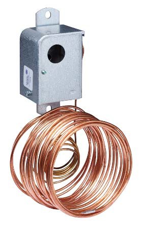
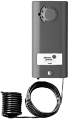
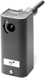
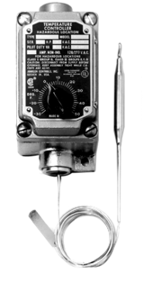
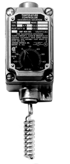
![]() A11 Series Low Temperature Cutout Controls
A11 Series Low Temperature Cutout Controls
![]()
![]()
![]()
Description
A11 Series Low Temperature Cutout Controls are available with single-pole, single-throw (SPST) or single-pole, double-throw (SPDT) contact action. Typical applications include the sensing of low temperature conditions to avoid over cooling or icing of hydronic coils, cooling coils, and liquid-handing pipes. The controls are compact and sturdy, and have an adjustable temperature setpoint range with a fixed differential. The range adjustment screw is accessible at the bottom of the control, and at the top of the control when the cover is removed.
The A11 Controls are compact and sturdy and feature an adjustable range with a fixed differential. The range adjustment screw is accessible at the bottom of the control or at the top, when the cover is removed. A factory-set low temperature stop is available when specified.
Refer to the A11 Series Low Temperature Cutout Controls Product Bulletin (LIT-125010) for important product application information.
Electrical Rating
| Motor Rating | 120 V | 208 V | 240 V |
| Motor Description | |||
| AC Full Load Amperes | 16.0 | 9.2 | 8.0 |
| AC Locked Rotor Amperes | 96.0 | 55.2 | 48.0 |
| Non-Inductive Amperes | 16.0 | 9.2 | 8.0 |
| Pilot Duty | 125 VA, 24 to 277 VAC | ||
Selection Chart
Features
- precision repeat accuracy remains unaffected by ambient temperature at the control diaphragm cup and 4 ft (1.2 m) capillary (20 ft [6.1 m] sensing bulb must be in the controlled area)
- trip-free manual reset allows the lever to reset. You must press and release the lever before operation resumes.
- precision snap-acting contacts in a dust protected enclosure enables the A11 Control to operate to the fullest potential
- direct reading scale provides
easy-to-adjust setpoint. Adjustments can be made from the top or bottom of the control.
Repair Information
If the A11 Series Low Temperature Cutout Control fails to operate within its specifications, replace the unit. For a replacement control, contact the nearest Johnson Controls® representative.
A11 Series Low Temperature Cutout Control
| Model | Description |
| A11A | SPST, open low, manual reset |
| A11B | SPST, open low, automatic recycle |
| A11D | SPDT, manual reset |
| A11E | SPDT, automatic recycle |
( )
( )
( )
( )
( )
( )
( )
( )
( )
( )
( )
( )
( )
( )
( )
( )
( )
( )
( )
( )
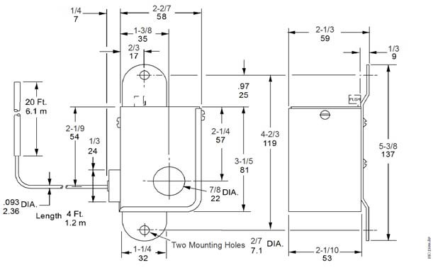
A11 Series Low Temperature Cutout Controls Dimensions, in. (mm)
| Single-Stage Electromechanical Temperature Controls |
A11 Series Low Temperature Cutout Controls (Continued)
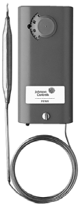
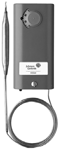
![]()
![]()
![]()
![]()
Technical Specifications
| A11 Low Temperature Cutout Controls | ||
| Product Codes | A11A: SPST, open low, manual reset
A11B: SPST, open low, automatic recycle A11D: SPDT, manual reset A11E: SPDT, automatic recycle |
|
| Range Cutout | 35 to 45°F (2 to 7°C) | |
| Differential | A11A and A11D: Temperature must be 12°F (6.7°C) above cutout point before control can be reset. A11B and A11E: 12°F (6.7°C) | |
| Ambient Temperature | Minimum: 0°F (-18°C) Maximum: 140°F (60°C) | |
| Maximum Temperature at Bulb | 250°F (121°C) | |
| Sensing Element | 1/8 in. x 20 ft (3 mm x 6.1 m) or 1/8 in. x 40 ft (3 mm x 12.2 m) | |
| Capillary Length | 4 ft (1.2 m) | |
| Switch | Snap-acting contacts in dust-protected enclosure | |
| Material | Case: 0.6 (2 mm) cold rolled steel Cover: 0.3 in. (1 mm) cold rolled steel | |
| Finish | Galvanized steel | |
| Conduit Opening | 22 mm (9/10 in.) hole for 13 mm (1/2 in.) conduit | |
| Mounting Bracket | Standard on all controls | |
| Shipping Weight | Individual pack: 1.8 lb (0.8 kg)
Overpack of 20 units: 38 lb (17 kg) |
|
| Electrical Rating | Pilot Duty: 125 VA, 24 to 277 VAC | |
| Motor Ratings | AC Full Load Ampere: 120 V = 16.0 A, 208 V = 9.2 A, 240 V = 8.0 A
AC Locked Rotor Ampere: 120 V = 96.0 A, 208 V = 55.2 A, 240 V = 48.0 A Non-Inductive Ampere: 120 V = 16.0 A, 208 V = 9.2 A, 240 V = 8.0 A |
|
| Compliance | United States | UL Listed, File SA516, SDFY |
| FCC Compliant to CFR 47, Part 15 Subpart B, Class A | ||
| Canada | UL Listed, CSA Class No. 1222 01, File LR948 | |
| Industry Canada, ICES-003 | ||
Single-Stage Electromechanical Temperature Controls Code No. LIT-1927010
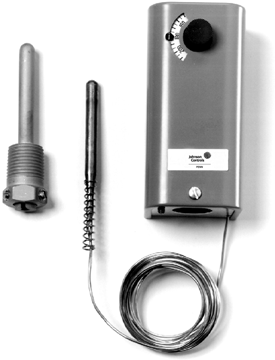
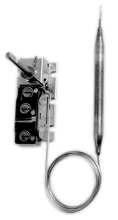
![]() A19 Series Remote Bulb Control
A19 Series Remote Bulb Control
![]()
![]()
![]()
Description
The A19 Series Controls are single-stage temperature controls that incorporate environmentally friendly liquid-filled sensing elements.
Refer to the A19 Series Hot Water Heating Controls Well Immersion Product Bulletin (LIT-125025) for important product application information.
Features
- wide temperature ranges available
- constant differential throughout the entire range
- compact enclosure
- fixed or adjustable differential available
- variety of sensing element styles
- unaffected by cross-ambient conditions
Applications
The A19 is suitable for temperature control in HVAC/R applications.
Selection Charts
A19 Series Remote Bulb Control1
A19 Series
![]()
Y
R
B
Action on Increase of Temperature
![]()
![]()
![]()
a19.eps
A19 Series
Terminal Arrangement for Single-Pole, Double-Throw (SPDT)
A19ABC-24 Remote Bulb Control
- Specify the control model code number, packing nut code number (if required), and bulb well code number (if required).
- Replaces White-Rodgers® 1609-101
3. Replaces White-Rodgers 1609-12, -13; Ranco® 010-1408, -1409, – 1410, -1490, 060-110; Honeywell® L6018C-1006, L6021A-1005, T675A-1011, -1508, -1516,
-1821, T4301A-1008, T6031A-1011, T6031A-1029
4. Case-Compensated
| Single-Stage Electromechanical Temperature Controls |
A19 Series Remote Bulb Control (Continued)
![]()
![]()
![]()
![]()
Replacement Parts
| Product Code Number | Description |
| CVR28A-617R | Concealed adjustment cover |
| CVR28A-618R | Visible scale cover |
| KNB20A-602R | Replacement Knob Kit |
Accessories
A packing nut is available for closed tank application. Specify the code number FTG13A-600R.
Bulb wells (WEL14A Series) are available for liquid immersion applications. See the selection chart or the Bulb Wells Catalog Page (LIT-1922135).
Technical Specifications
Electrical Ratings
| Motor Ratings VAC | 120 | 208 | 240 |
| Wide Range – Adjustable Differential | |||
| AC Full Load A | 16.0 | 9.2 | 8.0 |
| AC Locked Rotor A | 96.0 | 55.2 | 48.0 |
| Non-Inductive A1 | 22 A, 120 to 277 VAC | ||
| Pilot Duty | 125 VA, 24 to 600 VAC | ||
| Fixed Differential and Close Differential | |||
| AC Full Load A | 6.0 | 3.4 | 3.0 |
| AC Locked Rotor A | 36.0 | 20.4 | 18.0 |
| Non-Inductive A | 10 A, 24 to 277 VAC | ||
| Pilot Duty | 125 VA, 24 to 277 VAC | ||
| Case Compensated – Fixed Differential A19AAC-4 | |||
| AC Full Load A | 16.0 | 9.2 | 8.0 |
| AC Locked Rotor A | 96.0 | 55.2 | 48.0 |
| Non-Inductive A1 | 22 A, 120 to 277 VAC | ||
| Pilot Duty | 125 VA, 24 to 600 VAC | ||
| A19AAD-12 | |||
| AC Full Load A | 6.0 | 3.4 | 3.0 |
| AC Locked Rotor A | 36.0 | 20.4 | 18.0 |
| Non-Inductive A | 10 A, 24 to 277 VAC | ||
| Pilot Duty | 125 VA, 24 to 277 VAC | ||
| Manual Reset | |||
| AC Full Load A | 16.0 | 9.2 | 8.0 |
| AC Locked Rotor A | 96.0 | 55.2 | 48.0 |
| Non-Inductive A | 16.0 | 9.2 | 8.0 |
| Pilot Duty | 125 VA, 24 to 600 VAC | ||
1. SPST and N.O. contact of SPDT control;
SPDT N.C. contact- 16 amperes 120 to 277 VAC
Single-Stage Electromechanical Temperature Controls Code No. LIT-1927015
 A19 Series High Range Temperature Control
![]()
![]()
![]()
Description
The A19 Series Controls are single-stage temperature controls that incorporate liquid-filled sensing elements.
Refer to the A19 Series Hot Water Heating Controls Well Immersion Product Bulletin (LIT-125025) for important product application information.
Features
- wide temperature ranges available
- constant differential throughout the entire range
- single-pole, single-throw (SPST) or single-pole, double-throw (SPDT) snap-acting switches
- fixed or adjustable differential available
- unaffected by barometric pressure changes
- unaffected by cross-ambient conditions
- compact enclosure
- variety of sensing element styles
Applications
The A19s are suitable for temperature control in HVAC/R applications.
Selection Charts
A19 Series High Range Temperature Control
A19 Series
![]()
Y
R
B
Action on Increase of Temperature
![]()
![]()
![]()
a19.eps
A19 Series
Terminal Arrangement for SPDT
A19AAB Temperature Control
| Product Code | Switch
Action |
Range
°F (°C) |
Diff F° (C°)
(Factory Set) |
Bulb and
Capillary |
Bulb Well No. | Range
Adjuster |
Max Bulb
Temp °F (°C) |
| A19AAB-4C | SPST, open high | 30 to 110
(-1 to 43) |
3-1/2 (1.9) | 3/8 in. x 5 in.
copper 6 ft. capillary2 |
WEL14A-602R | Screwdriver slot
Visible scale |
140 (60) |
| A19AAB-7C | SPST, open high Oven Thermostat | 100 to 300
(38 to 149) |
7 (3.9) | 3/16 in. x 9-1/2 in. copper 6 ft. capillary | – | Knob Visible scale | 350 (177) |
| A19AAB-10C | SPST, open high Oven Thermostat | 200 to 550
(93 to 288) |
10 (5.6) | 3/16 in. x 6 in. copper 8 ft. capillary | – | Convertible | 620 (327) |
| A19AAC-9C | SPDT | 100 to 240 | 6 (3.3) | 3/8 in. x 3-1/2 in. copper 6 ft. capillary2 | WEL14A-602R | Screwdriver slot Visible Scale | 290 (143) |
| A19ABB-2C | SPST, open high Remote Bulb Thermostat | 50 to 200
(10 to 93) |
Adjustable 6 to 24
(3 to 13) |
0.290 in. x 2-1/2 in. copper 10 ft. capillary | – | Knob
Visible Scale |
240 (116) |
| A19ABB-7C | 50 to 201
(10 to 94) |
7 x 64 mm | 240 (116) |
- Specify code number, and closed tank fitting (Code Number FTG13A-600R), or bulb well, if required.
- With 3-inch bulb support
Replacement Parts
| Product Code Number | Description |
| CVR28A-617R | Concealed adjustment cover |
| CVR28A-618R | Visible scale cover |
| KNB20A-602R | Replacement knob kit |
Technical Specifications
Electrical Ratings
| Motor Ratings VAC | 120 | 208 | 240 |
| AC Full Load A | 16.0 | 9.2 | 8.0 |
| AC Locked Rotor A | 96.0 | 55.2 | 48.0 |
| Non-Inductive A1 | 22 A, 120 to 277 VAC | ||
| Pilot Duty | 125 VA, 24 to 600 VAC | ||
1. SPST and N.O. contact of SPDT control SPDT N.C. contact – 16 A, 120 to 277 VAC
| Single-Stage Electromechanical Temperature Controls Code No. LIT-1927020 |
 A19 Series Thermostat for Crop Drying
![]()
![]()
![]()
Description
The A19 Series are single-stage temperature controls that incorporate liquid-filled sensing elements.
Refer to the A19 Series Utility Thermostats for Farm, Industrial, and Commercial Use Product Bulletin (LIT-125030) for important product application information.
Technical Specifications
The maximum bulb temperature for the A19AAE-3 is 200°F (93°C) and for the A19ABB-2 is 240°F (116°C).
Electrical Rating 120 VAC
| Motor Ratings VAC | 120 | 208 | 240 |
| A19AAE-3 | |||
| AC Full Load A | 6.0 | 3.4 | 3.0 |
| AC Locked Rotor A | 36.0 | 20.4 | 18.0 |
| Non-Inductive or Resistance Load A (Not Lamp Loads) | 10 A
120 to 277 VAC |
||
| Pilot Duty | 125 VA,
24 to 277 VAC |
||
| A19ABB-2 | |||
| AC Full Load A | 10.0 | – | 6.0 |
| AC Locked Rotor A | 60.0 | – | 36.0 |
| Pilot Duty | 125 VA,
24 to 600 VAC |
||
Features
- designed for high temperature applications
- narrow (2F° fixed) or wide adjustable differentials
Applications
Crop drying thermostat energizes gas valve to maintain temperature.
Repair Information
If the A19 Series Thermostat for Crop Drying fails to operate within its specifications, replace the unit. For a replacement thermostat, contact the nearest Johnson Controls® representative.
Selection Chart
A19AAE-3 Thermostat
| Product | Switch
Action |
Range
°F (°C) |
Differential
F°(C°) |
Bulb and
Capillary |
Range
Adjuster |
Max. Bulb
Temperature °F (°C) |
| A19AAE-3C | Single-Pole, | 80 to 180
(27 to 82) |
2 (1.1) fixed | 1/8 in. x 1-1/4 in.
copper-coiled 10 ft capillary |
Knob
Ext. scale |
200 (93) |
| A19ABB-2C | SPST open high | 50 to 200
(10 to 93) |
6 to 24
(3 to 13) adjustable |
0.290 in. x 2-1/2 in.
10 ft. capillary |
Knob
Ext. Scale |
240 (116) |
| Single-Stage Electromechanical Temperature Controls Code No. LIT-1927030 |
![]() A19 Series Hot Water Temperature Control (Well Immersion)
A19 Series Hot Water Temperature Control (Well Immersion)
![]()
![]()
![]()
Description
The A19 Series Temperature Controls are a universal replacement control for open high or single-pole, double-throw (SPDT) applications. The control is furnished with a well assembly for 1/2 in. tapping.
Refer to the A19 Series Hot Water Heating Controls Well Immersion Product Bulletin (LIT-125025) for important product application information.
Features
- liquid-filled element provides rapid response to temperature change
- adjustable differential
- universal replacement
Applications
This operating control is ideal for hot water boilers.
Selection Charts
A19 Series Hot Water Temperature Control (Well Immersion)
 A19ABC-11
Temperature Control
A19ABC-12 Temperature Control
Replacement Parts
| Product Code Number | Description |
| CVR28A-617R | Concealed adjustment cover |
| CVR28A-618R | Visible scale cover |
| KNB20A-602R | Knob kit |
Technical Specifications
Electrical Ratings
| Motor Ratings VAC | 120 | 240 |
| AC Full Load A | 10.0 | 6.0 |
| AC Locked Rotor A | 60.0 | 36.0 |
| Pilot Duty | 125 VA, 24 to 600 VAC | |
Single-Stage Electromechanical Temperature Controls Code No. LIT-1927035
 A19 Temperature Control Less Enclosure (SPDT, Close Differential)
![]()
![]()
![]()
Description
The A19 Temperature Control Less Enclosure is an open-type temperature control for mounting in cases or enclosures.
Refer to the A19 Series Temperature Controls Less Enclosure Product Bulletin (LIT-125045) for important product application information.
Features
This control is designed with single-pole, double-throw (SPDT) contacts for open high or open low applications.
Applications
Use for panel-mounted temperature control for a packaged terminal air conditioner or for
self-contained HVAC equipment.
Selection Charts
A19 Series
![]()
Y
R
B
Action on Increase of Temperature
![]()
![]()
![]()
a19.eps
A19 Series
Terminal Arrangement for SPDT
A19AGF-31 Temperature Control
A19 Temperature Control Less Enclosure (SPDT, Close Differential) Replacement Parts
Technical Specifications Electrical Ratings
| Motor Ratings VAC | 120 | 208 | 240 |
| AC Full Load A | 6.0 | 3.4 | 3.0 |
| AC Locked Rotor A | 36.0 | 20.4 | 18 |
| Non-Inductive | 10 A, 120 to 277 VAC | ||
| Pilot Duty | 125 VA, 24 to 277 VAC | ||
- back mounting
- knob supplied by the customer
| Single-Stage Electromechanical Temperature Controls Code No. LIT-1927045 |
![]() A19 Series Thermostat for Hazardous Locations
A19 Series Thermostat for Hazardous Locations
![]()
![]()
![]()
Description
The A19 Series Thermostat provides remote bulb or coiled bulb sensing for hazardous environments.
Refer to the Types A19AUC, A19BUC Fixed Differential Thermostat For Hazardous Location Product Bulletin (LIT-121035) for important product application information.
Features
- precision enclosed switch and a liquid-filled sensing element provides repeat accuracy that is unaffected by barometric pressure and cross-ambient temperature fluctuations
- single-pole, double-throw (SPDT) switch provides open high or close high action for heating or cooling
- electrical rating permits direct control of most equipment
Selection Chart
Applications
These thermostats are designed for use in grain elevators, chemical and powder plants, mines, oil refineries, and similar sites. For use in Class I, Group D and Class II, Groups E, F, and G hazardous locations.
Repair Information
If the A19 Series Thermostat for Hazardous Locations fails to operate within its specifications, replace the unit. For a replacement thermostat, contact the nearest Johnson Controls® representative.
Technical Specifications
Electrical Ratings
| Motor Ratings VAC | 120 | 208 | 240 | 277 |
| Full Load Amperes | 16.0 | 9.2 | 8.0 | – |
| Locked Rotor Amperes | 96.0 | 55.2 | 48.0 | – |
| Non-Inductive Amperes | 22.0 | 22.0 | 22.0 | 22.0 |
| Pilot Duty | 125 VA, 24 to 600 VAC | |||
A19AUC
Thermostat
A19BUC
Thermostat
Single-Stage Electromechanical Temperature Controls Code No. LIT-1927050
 A19 Series Coiled Bulb Space Thermostat
![]()
![]()
![]()
Description
The A19 Series Thermostat is a wide range temperature control with air coil sensing element.
Refer to the A19 Series Utility Thermostats for Farm, Industrial, and Commercial Use Product Bulletin (LIT-125030) for important product application information.
Features
- wide temperature range
- NEMA 1 enclosure
Applications
Use for return air or space temperature sensing.
Selection Charts
A19 Series Coiled Bulb Space Thermostat
A19 Series
![]()
Y
R
B
Action on Increase of Temperature
![]()
![]()
![]()
a19.eps
A19 Series
Terminal Arrangement for SPDT
A19BAC Thermostat
Technical Specifications
Electrical Ratings
| Motor Ratings VAC | 120 | 208 | 240 |
| A19BAB, A19BAC | |||
| AC Full Load A | 16.0 | 9.2 | 8.0 |
| AC Locked Rotor A | 96.0 | 55.2 | 48.0 |
| Non-Inductive or Resistance Load A1 (Not Lamp Loads) | 22 A,
120 to 277 VAC |
||
| Pilot Duty | 125 VA,
24 to 600 VAC |
||
| A19BAF | |||
| AC Full Load A | 6.0 | 3.4 | 3.0 |
| AC Locked Rotor A | 36.0 | 20.4 | 18.0 |
| Non-Inductive or Resistance Load A (Not Lamp Loads) | 10 A,
120 to 277 VAC |
||
| Pilot Duty | 125 VA,
24 to 277 VAC |
||
| Cooling – A19BBC | |||
| AC Full Load A | 16.0 | 9.2 | 8.0 |
| AC Locked Rotor A | 96.0 | 55.2 | 48.0 |
| Non-Inductive or Resistance Load A1 (Not Lamp Loads) | 22 A,
120 to 277 VAC |
||
| Pilot Duty | 125 VA,
24 to 600 VAC |
||
1. Replaces White-Rodgers® 201-16, -8, 2A37-1; Ranco® 010-1418, -1802, 016-594, C30-C1101; Honeywell® T631A, T696A, T6054 A1005.
Replacement Parts
| Product Code Number | Description |
| CVR28A-617R | Concealed adjustment cover |
| CVR28A-618R | Visible scale cover |
| KNB20A-602R | Knob kit |
1. SPST and only one side of SPDT control; SPDT – 16 A 120 to 277 VAC
| Single-Stage Electromechanical Temperature Controls Code No. LIT-1927055 |
![]()
Description
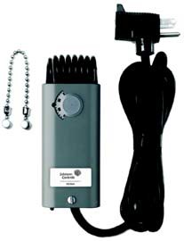
A19 Thermostat for Portable Heaters (Chain Mount and Drop Cord Electrical Connection)
Applications
![]()
![]()
![]()
The A19 Series Thermostat is a sturdy compact thermostat designed especially for temporary installations.
Refer to the Type A19BAG Thermostat for Portable Heaters with Thermostat Extension Cord and Beaded Chain Hanger Product Bulletin (LIT-121040) for important product application information.
Features
- 6-foot extension cord with piggyback style plug
- NEMA 1 enclosure
- chain mount
Selection Chart
- on/off control of portable space heaters
- agriculture
Repair Information
If the A19 Thermostat for Portable Heater fails to operate within its specifications, replace the unit. For a replacement thermostat, contact the nearest Johnson Controls® representative.
Technical Specifications
Electrical Ratings
| Motor Ratings VAC | 120 |
| AC Full Load A | 15 |
| AC Locked Rotor A | 90 |
A19BAG-1 Thermostat
| Product Code | Switch Action | Range
°F (°C) |
Differential
F° (C°) |
Maximum Bulb
Temperature °F (°C) |
| A19BAG-1C | Single-Pole,
Single-Throw (SPST) open high No-Heat position |
35 to 95
(2 to 35) |
3 (1.7)
Non-adjustable |
140 (60) |
| Single-Stage Electromechanical Temperature Controls Code No. LIT-1900402 |
![]() A19 Thermostat for Portable Cooling Applications (Chain Mount and Drop Cord Electrical Connection)
A19 Thermostat for Portable Cooling Applications (Chain Mount and Drop Cord Electrical Connection)
![]()
![]()
![]()
Description
The A19 Series Thermostat is a sturdy compact thermostat designed especially for temporary installations.
Refer to the A19 Series Hot Water Heating Controls Well Immersion Product Bulletin (LIT-125025) for important product application information.
Features
- 6-foot extension cord with piggyback style plug
- NEMA 1 enclosure
- chain mount
- remote sensing bulb with 6 ft (1.8 m) capillary tube
Selection Chart
Applications
- on/off control of portable cooling applications
- home brewing
Repair Information
If the A19 Thermostat for Portable Cooling Applications (Chain Mount and Drop Cord Electrical Connections) fails to operate within its specifications, replace the unit. For a replacement thermostat, contact the nearest Johnson Controls® representative.
Technical Specifications
Electrical Ratings
| Motor Ratings VAC | 120 |
| AC Full Load Amperes | 15 |
| AC Locked Rotor Amperes | 90 |
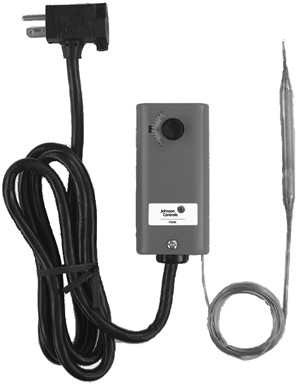
A19AAT-2 Thermostat
| Product | Switch
Action |
Range
°F (°C) |
Differential
F° (C°) |
Maximum Bulb
Temperature °F (°C) |
| A19AAT-2C | Single-Pole, Single-Throw
(SPST) open low |
20 to 80 (-7 to 27) | 3-1/2 ± 2 (2 ± 1.11)
Non-adjustable |
140 (60) |
Single-Stage Electromechanical Temperature Controls Code No. LIT-1927060
 A19 Series Automatic Changeover with Strap-On Mounting
![]()
![]()
![]()
Description
The A19 Series Changeover is a control for use with combination heating and cooling thermostats.
Refer to the A19CAC Type Automatic Changeover Control Product Bulletin
(LIT-125065) for important product application information.
Features
This control automatically selects the correct thermostat function.
Applications
Recommended for convectors, fan coils, and blast coil units, and similar devices. The A19CAC-2 Control can be mounted directly on either a vertical or a horizontal pipe, using the can mounting strap supplied with control. The A19CAC-1 Control has a remote bulb for greater mounting convenience.
Selection Charts
A19 Series
![]()
Y
R
B
Action on Increase of Temperature
![]()
![]()
![]()
a19.eps
A19 Series
Terminal Arrangement for SPDT
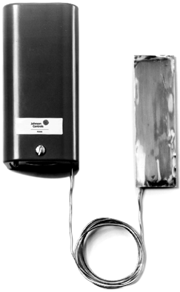
A19CAC-1 Control (Remote Bulb Model)
Technical Specifications
A19 Series Automatic Changeover with Strap-on Mounting
| Product Code Number | Switch Action | Range °F (°C) | Differential F°(C°) | Mounting |
| A19CAC-1C | Single-Pole, | 60 to 90 (16 to 32) | 10 (5.6) | 42 in. Capillary |
| A19CAC-2C | SPDT | 60 to 90 (16 to 32) | 10 (5.6) | Direct |
Replacement Parts
- maximum case ambient temperature: 131°F (55°C)
- maximum bulb temperature: 250°F (121°C)
Electrical Ratings
| Motor Ratings VAC | 120 | 240 |
| AC Full Load A | 10.0 | 6.0 |
| AC Locked Rotor A | 60.0 | 36.0 |
| AC Non-Inductive A | 10.0 | 6.0 |
| Pilot Duty | 125 VA,
24 to 240 VAC |
|
| Product Code Number | Description |
| CVR28A-617R | Concealed adjustment cover |
Single-Stage Electromechanical Temperature Controls Code No. LIT-1927065
 A19D Series Surface Mounted Temperature Controls
![]()
![]()
![]()
Description
The A19D Series Surface Mounted Temperature Controls are reliable, durable On/Off temperature controls with line-voltage single-pole, double-throw (SPDT) switches. The A19D Series Controls are designed primarily for fluid piping applications and include two adjustable mounting straps for mounting the control directly to a pipe.
Refer to the A19D Series Surface Mounted Temperature Controls Product Bulletin
(LIT-125070) for important product application information.
Features
- SPDT switch action provides either high or low temperature detection.
- sealed, dust-protected switch provides reliable and durable On/Off control for commercial and industrial applications.
- color-coded electrical terminals simplify wiring the controls.
- sensing element insulated from the control case minimizes the effects of ambient temperature on the control setpoint.
Selection Chart
- convertible range adjuster kit provides knob, screwdriver, or concealed adjustment options.
- multi-position mounting capability allows you to mount the control in any position on horizontal, vertical, or angled pipes.
- NEMA 1 enclosure provides protection against contact with the control’s electrical components and protects the switch and electrical terminals from incidental contact.
Applications
Typical A19D control applications include high temperature detection on boiler applications and low temperature detection on unit heaters coil applications.
![]()
![]()
![]()
SPDT Switch
Switch Action 6
At Setpoint Y-R is open
B-R is closed
On Increase Y-R closes B-R opens
| Y
R B |
A19D Series Control Switch Action
FIG:6SPDT_chngHI
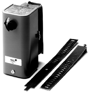
A19D Series Temperature Control
Repair Information
If the A19D Series Surface Mounted Temperature Control fails to operate within its specifications, replace the unit. For a replacement control, contact the nearest Johnson Controls® representative.
Technical Specifications
| A19D Series Surface Mount Temperature Controls | ||||
| Product Code Number | A19DAC: SPDT switch, standard differential
A19DAF: SPDT switch, narrow differential |
|||
| Adjustable Temperature Range | A19DAC: 100 to 240°F or 40 to 120°C A19DAF: 200 to 240°F (95 to 120°C) | |||
| Fixed Temperature Differential | A19DAC: 10 F° or 6.0 C° A19DAF: 3-1/2 F° (1.9 C°) | |||
| Maximum Ambient Operating Temperature | Controller Housing: 140°F (60°C) Sensor Element: 250°F (121°C) | |||
| Switch Contact Action | SPDT, Snap Acting, Enclosed Dust Protected Pennswitch
Red to Yellow Terminal Contacts Close on Temperature Increase Red to Blue Terminal Contacts Open on Temperature Increase |
|||
| Terminal Screws | No. 8-32 x 1/4 in. Binder Head with Cup Washers | |||
| Electrical Ratings | Motor Rating VAC | A19DAC: Standard Differential
120 240 |
A19DAF: Narrow Differential
120 240 |
|
| Full Load Amperes Locked Rotor Amperes Non-Inductive Amperes Pilot Duty | 10.0 6.0
60.0 36.0 10.0 6.0 125 VA, 24 to 277 VAC |
6.0 3.4
36.0 20.4 6.0 3.4 125 VA, 24 to 277 VAC |
||
| Enclosure | NEMA Type 1 General Purpose; Cold Rolled Steel, Gray Baked Enamel | |||
| Mounting | Clamp-On (Straps Included) | |||
| Shipping Weight | 1-1/5 lb (.54 kg) | |||
| Compliance | UL Guide No. XAPX, File E6688 CSA Class No. 4813 02, File LR948
C-Tick |
|||
| Single-Stage Electromechanical Temperature Controls Code No. LIT-1927070 |
![]() A19 Flange Mounted Duct Thermostat
A19 Flange Mounted Duct Thermostat
![]()
![]()
![]()
Description
The A19 Flange Mounted Duct Thermostat is a wide-range temperature control with a special air coil sensing element and an adjustable mounting flange.
Refer to the A19 Series Hot Water Heating Controls Well Immersion Product Bulletin (LIT-125025) for important product application information.
Features
- single-pole, double-throw (SPDT) snap-action switch
- unaffected by barometric pressure or cross-ambient temperatures
- flat flange mounting with the coil element permits positioning the sensing bulb in the appropriate portion of the air stream
Selection Charts
A19 Flange Mounted Duct Thermostat
Applications
These duct thermostats are used on rooftop units, make-up heaters, duct heaters, and air handling systems of all types.
Technical Specifications
Electrical Ratings
| Motor Ratings VAC | 120 | 208 | 240 |
| AC Full Load A | 6.0 | 3.4 | 3.0 |
| AC Locked Rotor A | 36.0 | 20.4 | 18.0 |
| Non-Inductive | 10 A, 120 to 277 VAC | ||
| Pilot Duty | 125 VA, 24 to 277 VAC | ||
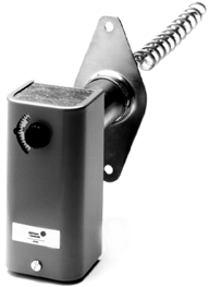
A19EAF Thermostat
Replacement Parts
| Product Code Number | Description |
| CVR28A-618R | Visible scale cover |
| Single-Stage Electromechanical Temperature Controls Code No. LIT-1927075 |
![]() A19 Series Fan or Cutout Control (Liquid Expansion Bulb)
A19 Series Fan or Cutout Control (Liquid Expansion Bulb)
![]()
![]()
![]()
Description
The A19 Series Fan or Cutout Control is a wide range temperature control with adjustable dial stops and mounting flange.
Refer to the A19E Series Warm Air Fan and Duct Controls Low or Line Voltage Product Bulletin (LIT-125075) for important product application information.
Features
- liquid charged element for fast response
- may be mounted in any position
Applications
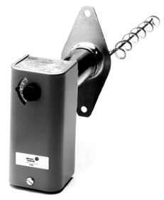 This control is designed for low or line voltage applications including warm air or furnace fan control.
Selection Chart
A19 Series Fan or Cutout Control (Liquid Expansion Bulb)
A19EBA, A19EBB, A19EBC
A19EDB Cutout Controls (A19EDB not for use as cutout control)
1. A19EDB-1 not for use as a limit control.
Replacement Parts
| Product Code Number | Description |
| CVR28A-618R | Visible scale cover |
Technical Specifications
Electrical Ratings
| Motor Ratings VAC | 120 | 208 | 240 | 277 |
| A19EBA, A19EBB | ||||
| AC Full Load A | 16.0 | 9.2 | 8.0 | – |
| AC Locked Rotor A | 96.0 | 55.2 | 48.0 | – |
| AC Non-Inductive A | 22.0 | 22.0 | 22.0 | 22.0 |
| Pilot Duty | 125 VA, 24 to 600 VAC | |||
| A19EBC | ||||
| AC Full Load A | 16.0 | 9.2 | 8.0 | – |
| AC Locked Rotor A | 96.0 | 55.2 | 48.0 | – |
| AC Non-Inductive A | 16.0 | 16.0 | 16.0 | 16.0 |
| Pilot Duty | 125 VA, 24 to 600 VAC | |||
| A19EDB | ||||
| AC Full Load A | 16.0 | 9.2 | 8.0 | – |
| AC Locked Rotor A | 96.0 | 55.2 | 48.0 | – |
| AC Non-Inductive A | 22.0 | 22.0 | 22.0 | 16.0 |
| Pilot Duty | 125 VA, 24 to 600 VAC | |||
| Single-Stage Electromechanical Temperature Controls Code No. LIT-1927040 |
![]() A19 Temperature Control with Rainproof Enclosure
A19 Temperature Control with Rainproof Enclosure
![]()
![]()
![]()
Description
The A19 Temperature Control is a remote bulb temperature control with a rainproof (NEMA Type 3R) enclosure.
Refer to the A19 Series Hot Water Heating Controls Well Immersion Product Bulletin (LIT-125025) for important product application information.
Features
This control has a rainproof gasketed enclosure.
Selection Chart
Applications
Use for control of cooling tower sump heaters.
Repair Information
If the A19 Temperature Control with Rainproof Enclosure fails to operate within its specifications, replace the unit. For a replacement control, contact the nearest Johnson Controls® representative.
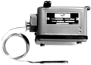
| Product
Code Number |
Switch
Action |
Range
°F (°C) |
Diff.
F° (C°) |
Bulb and
Capillary |
Bulb Well No.
(Order Separately) |
Range
Adjuster |
Max.
Bulb Temp. |
| A19ANC-1C | Single-Pole,
Double-Throw (SPDT) |
0 to 150
(-18 to 66) |
5 (2.8)
fixed |
3/10 x 2-1/2 in.
10 ft. capillary |
WEL11A-601R | Screwdriver
slot |
190 (88) |
Technical Specifications
- maximum bulb temperature: 190°F (88°C)
- maximum ambient temperature: 140°F (60°C)
Electrical Ratings
| Motor Ratings VAC | 120 | 208 | 240 | 277 | |
| AC Full Load A | 16.0 | 9.2 | 8.0 | — | |
| AC Locked Rotor A | 96.0 | 55.2 | 48.0 | — | |
| Non-Inductive A | When connected Single-Pole, Single-Throw (SPST) | 22.0 | 22.0 | 22.0 | 22.0 |
| When connected SPDT | 16.0 | 9.2 | 8.0 | 6.9 | |
| Pilot Duty | 125 VA, 24 to 600 VAC | ||||
| Single-Stage Electromechanical Temperature Controls Code No. LIT-1927080 |
![]() A19 Agricultural/Industrial Thermostat with NEMA 4X Enclosure
A19 Agricultural/Industrial Thermostat with NEMA 4X Enclosure
![]()
![]()
![]()
Description
The A19PRC is a single-stage temperature control designed for heating and ventilation applications. It features a raintight enclosure for use in agricultural and industrial applications that require compliance with Article 547 of the National Electrical Code. The A19PRC Thermostat has a rugged thermoplastic enclosure that meets NEMA 4X specifications.
Refer to the A19 Series Hot Water Heating Controls Well Immersion Product Bulletin (LIT-125025) for important product application information.
Features
- an O-ring sealed setpoint adjustment knob
- exposed portion of the liquid filled sensing elements are plated and plastic coated to resist damage in corrosive atmospheres
Selection Chart
Applications
Typical applications include controlling ventilation or heating equipment in animal confinement or industrial buildings.
Repair Information
If the A19 Agricultural/Industrial Thermostat with NEMA 4X Enclosure fails to operate within its specifications, replace the unit. For a replacement thermostat, contact the nearest Johnson Controls® representative.
Technical Specifications
Electrical Ratings
| Motor Ratings VAC | 120 | 208 | 240 |
| AC Full Load A | 16.0 | 9.2 | 8.0 |
| AC Locked Rotor A | 96.0 | 55.2 | 48.0 |
| Non-Inductive or Resistance Load A (Not Lamp Loads)1 | 22 A, 120/277 VAC | ||
| Pilot Duty | 125 VA, 24 to 600 VAC | ||
1. Single-pole, single-throw (SPST) and only one side of single-pole, double-throw (SPDT) control; SPDT – 16 A, 120 to 277 VAC
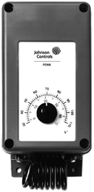
A19PRC Thermostat
| Product Code Number | Switch Action | Range °F (°C) | Differential F° (C°) | Bulb and Capillary | Range Adjuster |
| A19PRC-1C | SPDT | 30 to 110 (1 to 43) | 3 to 12 (1.7 to 6.7) | 1-3/8 in. x 2 -1/4 in. Coiled | Knob |
| Single-Stage Electromechanical Temperature Controls Code No. LIT-1927085 |
![]() A19 Industrial Thermostat (Watertight and Dusttight)
A19 Industrial Thermostat (Watertight and Dusttight)
![]()
![]()
![]()
Description
The A19 Industrial Thermostat is a wide range temperature control with rainproof enclosure, single-pole, double-throw (SPDT) switch, and 5F° fixed differential.
Refer to the A19 Series Hot Water Heating Controls Well Immersion Product Bulletin (LIT-125025) for important product application information.
Features
- rugged steel enclosure
- liquid filled sensing element (provides uniform control)
Applications
Use for refrigeration, air conditioning, and heating applications that require a NEMA 4 watertight and dusttight enclosure.
Accessories
Order code number WEL16A-600R bulb well, if required.
Repair Information
If the A19 Industrial Thermostat (Watertight and Dusttight) fails to operate within its specifications, replace the unit. For a replacement thermostat, contact the nearest Johnson Controls® representative.
Technical Specifications
Electrical Ratings
| Motor Ratings VAC | 120 | 208 | 240 |
| AC Full Load A | 16.0 | 9.2 | 8.0 |
| AC Locked Rotor A | 96.0 | 55.2 | 48.0 |
| Non-Inductive or Resistance Load A (Not Lamp Loads) | 16.0 | 9.2 | 8.0 |
| Pilot Duty | 125 VA,
24 to 600 VAC |
||
Selection Chart
| Product | Switch
Action |
Range
°F (°C) |
Differential
F° (C°) |
Bulb and
Capillary |
Bulb Well No.
(Order Separately) |
Range
Adjuster |
| A19KNC-1C | SPDT | 0 to 150
(-15 to 65) |
5 (2.8) fixed | 3/10 x 2-1/2 in.
10 ft. capillary |
WEL16A-600R | Knob |
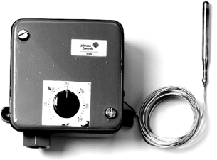
A19KNC-1 Thermostat
| Single-Stage Electromechanical Temperature Controls Code No. LIT-1900403 |
A19 Temperature Control with NEMA 4X Enclosure (Remote Bulb)
![]()
![]()
![]()
![]()
Description
The A19 Temperature Control is a remote bulb temperature control with a watertight NEMA 4X enclosure.
Refer to the A19 Series Hot Water Heating Controls Well Immersion Product Bulletin (LIT-125025) for important product application information.
Applications
- cooling tower sump heaters
- control of heating or ventilating equipment
Technical Specifications
Maximum ambient temperature: 140°F (60°C).
Electrical Ratings
Features
- watertight gasketed thermoplastic enclosure that meets NEMA 4X specifications
- concealed setpoint adjustment
Repair Information
If the A19 Temperature Control with NEMA 4X Enclosure (Remote Bulb) fails to operate within its specifications, replace the unit. For a replacement control, contact the nearest Johnson Controls® representative.
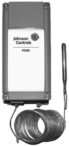
A19QSC Temperature Control
| Motor Ratings VAC | 120 | 208 | 240 | 277 | |
| AC Full Load Amperes | 16.0 | 9.2 | 8.0 | — | |
| AC Locked Rotor Amperes | 96.0 | 55.2 | 48.0 | — | |
| Non-Inductive
Amperes |
When connected
Single-Pole, Single-Throw (SPST) |
22.0 | 22.0 | 22.0 | 22.0 |
| When connected
Single-Pole, Double-Throw (SPDT) |
16.0 | 9.2 | 8.0 | 6.9 | |
| Pilot Duty | 125 VA, 24 to 600 VAC | ||||
Selection Chart
| Single-Stage Electromechanical Temperature Controls Code No. LIT-1927090 |
![]() A19 Water Chiller Control with Locked Cut-Out/Adjustable Cut-In
A19 Water Chiller Control with Locked Cut-Out/Adjustable Cut-In
![]()
![]()
![]()
Description
The A19 Water Chiller Control is a remote bulb temperature control with limited setpoint range, adjustable differential, and adjustable cut-out.
Refer to the A19ZBA Type Temperature Control Product Bulletin (LIT-121065) for important product application information.
Features
- adjustable cut-out (38 to 47°F)
- wide differential adjustment range
Accessories
Selection Chart
Applications
Use for water chillers.
Repair Information
If the A19 Water Chiller Control with Locked Cut-Out/Adjustable Cut-In fails to operate within its specifications, replace the unit. For a replacement control, contact the nearest Johnson Controls® representative.
Technical Specifications
Maximum bulb temperature is 140°F (60°C).
Electrical Ratings
| Motor Ratings VAC | 120 | 208 | 240 |
| AC Full Load A | 16.0 | 9.2 | 8.0 |
| AC Locked Rotor A | 96.0 | 55.2 | 48.0 |
| Non-Inductive or Resistance Load A (Not Lamp Loads) | 16.0 | 9.2 | 8.0 |
| Pilot Duty | 125 VA, 24 to 277 VAC | ||
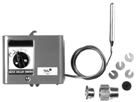
A19ZBA Water Chiller Control
| Product Code | Switch
Action |
Range
°F (°C) |
Differential
F° (C°) |
Bulb and
Capillary |
Bulb Well No. | Range
Adjuster |
| A19ZBA-1C | Single-Pole, Single-Throw
(SPST) Close high, open low |
38 to 80 (3 to 27) | 8 to 40 (4 to 22)
Adjustable |
3/8 in. x 3-7/16 in.
6 ft. capillary |
WEL14A-602R | Knob |
| Single-Stage Electromechanical Temperature Controls Code No. LIT-1927095 |
![]() A19 Defrost Duration and Fan Delay Control
A19 Defrost Duration and Fan Delay Control
![]()
![]()
![]()
Description
The A19 Defrost Duration and Fan Delay Control is a remote bulb control with adjustable defrost termination temperature and preset fan delay temperature.
Refer to the A19ZBC Type Temperature Control Product Bulletin (LIT-121071) for important product application information.
Features
- sensing element unaffected by barometer pressure and cross ambient temperature problems
- limited adjustment range
Applications
Use for defrost termination control for refrigerated display cases.
Selection Chart
Repair Information
If the A19 Defrost Duration and Fan Delay Control fails to operate within its specifications, replace the unit. For a replacement control, contact the nearest Johnson Controls® representative.
Technical Specifications
- maximum bulb temperature: 140°F (60°C)
- fan delay temperature: factory set at 25°F (-4°C)
Electrical Ratings
| Motor Ratings VAC | 120 | 208 | 240 |
| AC Full Load A | 16.0 | 9.2 | 8.0 |
| AC Locked Rotor A | 96.0 | 55.2 | 48.0 |
| Non-Inductive or Resistance Load A (Not Lamp Loads) | 16.0 | 9.2 | 8.0 |
| Pilot Duty | 125 VA, 24 to 277 VAC | ||
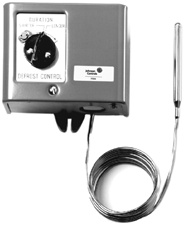
A19ZBC-2 Defrost Duration and Fan Delay Control
| Product Code | Switch
Action |
Defrost Termination
°F (°C) |
Bulb and
Capillary |
Range
Adjuster |
| A19ZBC-2C | Single-Pole,
Double-Throw (SPDT) |
45 to 85 (7 to 29) | 19/64 in. x 3-1/8 in.; 6 ft. capillary | Knob |
Single-Stage Electromechanical Temperature Controls Code No. LIT-1927105
 A25 Series Warm Air Limit Control with Manual Reset
![]()
![]()
![]()
Description
The A25 Warm Air Control Locks out on a temperature increase to the control setpoint. Manual reset is required before the electrical contacts can be reclosed.
The A25 Control is normally located in a return air duct and is wired to shut down air conditioning or ventilating fans when the temperature of the air becomes excessively hot.
Refer to the A25 Series Warm Air Control with Manual Reset Product Bulletin (LIT-125118) for important product application information.
Applications
Use for high temperature cut-out.
Features
A25 Series
![]()
Y
R
B
Action on Increase of Temperature
![]()
![]()
![]()
a25.eps
A25 Series Action Diagram
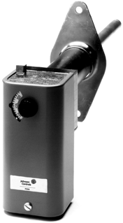
A25AN-1 Warm Air Limit Control
Technical Specifications
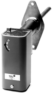
A25AP-1 Warm Air Limit Control
- trip-free reset lever does not permit restarting until the reset lever is manually released
- the rod and tube type sensing element provides positive control action
Repair Information
If the A25 Series Warm Air Limit Control with Manual Reset fails to operate within its specifications, replace the unit. For a replacement control, contact the nearest Johnson Controls® representative.
Selection Chart
The maximum element temperature is 300°F (149°C).
Electrical Ratings
| Motor Ratings VAC | 120 | 208 | 240 | 277 |
| AC Full Load A | 16.0 | 9.2 | 8.0 | – |
| AC Locked Rotor A | 96.0 | 55.2 | 48.0 | – |
| Non-Inductive A | 16.0 A at 120/277 VAC | |||
| Pilot Duty | 125 VA, 24 to 600 VAC | |||
Single-Stage Electromechanical Temperature Controls Code No. LIT-1927140
 A70 Series Four-Wire, Two-Circuit Temperature Control
![]()
![]()
![]()
Description
The A70 Series Temperature Control incorporates a vapor-charged sensing element. The A70G, A70H, and A70K have a four-wire, two-circuit contact block that contains two isolated sets of contacts.
The contacts are designed so that when the main contact opens, the auxiliary contact closes.
Refer to the A70, A72 Series Temperature Controls for Refrigeration and Heating Product Bulletin (LIT-125155) for important product application information.
Features
- long-life, snap-acting contacts
- automatic or manual reset models
Applications
Typical applications include energizing an indicator light after a low temperature cutout on a ventilating system.
Selection Charts
A70 Series
Action on Increase 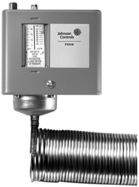 on Temperature
![]()
![]()
![]()
![]()
![]()
Li ne 2
M2
M1
Li ne 1
a70s.eps
A70 Series Action Diagram A70GA-1 Temperature Control
A70 Series Four-Wire, Two-Circuit Temperature Control
| Product Code | Switch Action | Range
°F (°C) |
Differential
F° (C°) |
Bulb and
Capillary |
Maximum Bulb
Temperature °F (°C) |
Range
Adjuster |
|
| Main Contacts | Auxiliary Contacts | ||||||
| A70GA-1C1 | Open low | Close low | 15 to 55
(-9.4 to 12.8) |
5 (2.8) | 20 ft of 1/8 in.
O.D. tubing |
400 (204.4) | Screwdriver slot |
| A70GA-2C | 35 to 80
(1.7 to 26.7) |
3 to 30
(-16.1 to -1.1), factory set at 12 (-11.1) |
3/8 in. x 3 in.
6 ft capillary |
250 (121) | |||
| A70HA-1C1 | 15 to 55
(-9.4 to 12.8) |
Manual reset | 20 ft of 1/8 in.
O.D. tubing |
400 (204.4) | |||
| A70HA-2C | 35 to 80
(1.7 to 26.7) |
3/8 in. x 3 in.
6 ft capillary |
250 (121) | ||||
| A70HA-14C | 15 to 55 | 20 ft of 1/8 in.
O.D. tubing |
400 (204.4) | ||||
| A70KA-1C | Open high | Close high | 100 to 170
(37.8 to 76.7) |
3/8 in. x 3 in.
6 ft capillary |
240 (116) | ||
1. On these models, the low cutout stop is set and sealed at 35°F (1.6°C). It cannot be set lower. The control responds only to the lowest temperature along any 14 to 16 in. section of the entire 20 ft element.
Replacement Covers
| Product Code Number | Description |
| CVR17A-620R | Automatic reset cover |
| CVR17A-621R | Manual reset cover |
Technical Specifications
Electrical Ratings
| Pole Number | LINE-M2 (Main) | LINE-M1 (Auxiliary) | ||||||||
| Motor Ratings VAC | 120 | 208 | 240 | 277 | 4801 | 6001 | 120 | 208 | 240 | 277 |
| AC Full Load A | 16.0 | 9.2 | 8.0 | — | 5.0 | 4.8 | 6.0 | 3.4 | 3.0 | — |
| AC Locked Rotor A | 96.0 | 55.2 | 48.0 | — | 30.0 | 28.8 | 36.0 | 20.4 | 18.0 | — |
| AC Non-Inductive A | 16.0 | 9.2 | 8.0 | 7.2 | — | — | 6.0 | 6.0 | 6.0 | 6.0 |
| Pilot Duty – Both Poles | 125 VA, 120 to 600 VAC and 57.5 VA, 120 to 300 VDC | |||||||||
1. Not compressor motor loads.
Single-Stage Electromechanical Temperature Controls Code No. LIT-1927145
![]()
Description
A72 Series Two-Pole Heavy Duty Temperature Controls (Adjustable Differential)
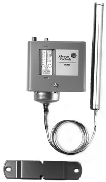 A72 Series
![]()
![]()
![]()
The A72 Series Temperature Controls incorporate a vapor charged sensing element and heavy duty contacts.
![]()
![]()
![]()
Refer to the A70, A72 Series Temperature Controls for Refrigeration and Heating
(LIT-125155) for important product application information.
Features
The double-pole, single-throw (DPST) contact block contains two isolated sets of contacts that make or break simultaneously.
Applications
Use for automatic control of heavy electrical loads.
Selection Charts
![]()
M1
Line 1
M2
Line 2
Action on Increase on Temperature
A72 Action Diagram
A72AA-3 Temperature Control
a27.eps
| Product Code | Switch
Action |
Range
°F (°C) |
Differential
F° (C°) |
Bulb and
Capillary |
Maximum Bulb
Temperature °F (°C) |
Range
Adjuster |
| A72AA-1C | DPST | -30 to 30
(-34 to -1) |
4 to 25
(2 to 14) |
3/8 in. x 3 in.1
6 ft capillary |
200
(93) |
Screwdriver slot |
| A72AA-2C | DPST | 15 to 55
(-9 to 13) |
3 to 30
(1.7 to 17) |
3/8 in. x 3 in.1
6 ft capillary |
200
(93) |
Screwdriver slot |
| A72AA-3C | DPST | 50 to 90
(10 to 32) |
3 to 30
(1.7 to 17) |
11/16 in. x 6-3/4 in. Cross ambient
6 ft capillary |
135
(57) |
Screwdriver slot |
| A72AP-1C2 | DPST
Close high Open low |
-10 to 65
(-23 to 18) |
4 to 40
(2 to 22) |
11/16 in. x 6-3/4 in. Cross ambient | 130
(54) |
Screwdriver slot |
- Packing nut assembly available for direct immersion applications, Code No. FTG13A-600R.
- Equipped with manual PUSH TO START button. Manual start feature is especially desirable on milk cooler jobs; permits manual start of the compressor when bulb temperature is between closing and opening setting of switch.
Replacement Covers
| Product Code Number | Description |
| CVR17A-620R | Automatic reset cover |
| CVR17A-621R | Manual reset cover |
Technical Specifications
Electrical Ratings
| Motor Ratings VAC | 120
Single-Phase |
2081
Single-Phase |
2401
Single-Phase |
2201
Two-Phase |
208
Three-Phase |
220
Three-Phase |
| Horsepower | 2 | 3 | 3 | 5 | 5 | 5 |
| AC Full Load A | 24.0 | 24.0 | 24.0 | 15.0 | 15.9 | 15.0 |
| AC Locked Rotor A | 144.0 | 144.0 | 144.0 | 90.0 | 95.4 | 90.0 |
| AC Non-Inductive A | 24.0 | 24.0 | 24.0 | – | – | – |
| DC Non-Inductive A2 | 3.0 | – | 0.5 | – | – | – |
| Pilot Duty | 125 VA, 120 to 600 VAC; 57.5 VA, 120 to 300 VDC | |||||
- These full load and locked rotor ampere (not horsepower) ratings apply to hermetic compressors only.
- This rating does not apply to the A72AP-1C Control.
| Single-Stage Electromechanical Temperature Controls Code No. LIT-1927160 |
 A72 Series Cooling Tower or Evaporative Condenser Controls (Single-Stage Temperature Control with Outdoor Enclosure)
![]()
![]()
![]()
Description
The A72AE and A72CE are wide range temperature controls with heavy duty double-pole, single-throw (DPST) contacts and neoprene-coated sensing elements.
Refer to the A72 Series Temperature Controls for Cooling Towers and Evaporated Condensers with Weather Resistant Enclosure Product Bulletin (LIT-125165) for important product application information.
Selection Chart
Features
Open high or close high models are available.
Applications
Use for control of cooling tower fans; motorized valves or solenoid operated valves.
Repair Information
If the A72 Series Cooling Tower or Evaporative Condenser Control fails to operate within its specifications, replace the unit. For a replacement control, contact the nearest Johnson Controls® representative.
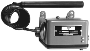
A72 Series Temperature Control
Technical Specifications
- ambient temperature limits: -65 to 150°F (-54 to 66°C)
- maximum bulb temperature: 170°F (77°C)
Electrical Ratings
| Motor Ratings VAC | 120
Single- Phase |
2081
Single- Phase |
2401
Single- Phase |
2201
Two- Phase |
208
Three- Phase |
220
Three- Phase |
| Horsepower | 2 | 3 | 3 | 5 | 5 | 5 |
| AC Full Load A | 24.0 | 24.0 | 24.0 | 15.0 | 15.9 | 15.0 |
| AC Locked Rotor A | 144.0 | 144.0 | 144.0 | 90.0 | 95.4 | 90.0 |
| AC Non-Inductive A | 24.0 | 24.0 | 24.0 | – | – | – |
| DC Non-Inductive A | 3.0 | – | 0.5 | – | – | – |
| Pilot Duty | 125 VA, 120 to 600 VAC; 57.5 VA, 120 to 300 VDC | |||||
1. These full load and locked rotor ampere (not horsepower) ratings apply to hermetic compressors only.
| Single-Stage Electromechanical Temperature Controls Code No. LIT-1927150 |
![]() A72AA Coiled Bulb Space Thermostat (Cooling)
A72AA Coiled Bulb Space Thermostat (Cooling)
![]()
![]()
![]()
Description
The A72 is a space sensing temperature control with heavy-duty contacts.
Refer to the A72 Series Temperature Controls for Cooling Towers and Evaporative Condensers with Weather Resistant Enclosure Product Bulletin (LIT-125165) for important product application information.
Applications
Use for compressor cycling for walk-in coolers and freezers.
Accessories
For replacement cover, order code number
CVR17A-620R.
Selection Chart
| Product Code
Number |
Switch
Action |
Range
°F (°C) |
Differential
F° (C°) |
Bulb and
Capillary |
Range
Adjuster |
| A72AA-4C | DPST
Close high, open low |
15 to 55
(-9 to 13) |
3 to 30
(1.7 to 17) |
Coiled copper
bulb |
Screwdriver
slot |
Maximum bulb temperature is 200°F (93°C).
Electrical Ratings
Features
Double-pole, single-throw (DPST) contact block contains two isolated sets of contacts that make or break simultaneously.
Repair Information
If the A72AA Coiled Bulb Space Thermostat fails to operate within its specifications, replace the unit. For a replacement thermostat, contact the nearest Johnson Controls® representative.
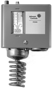
A72AA-4 Thermostat
| Motor Ratings VAC | 120
Single-Phase |
2081
Single-Phase |
2401
Single-Phase |
2201
Two-Phase |
208
Three-Phase |
220
Three-Phase |
| Horsepower | 2 | 3 | 3 | 5 | 5 | 5 |
| AC Full Load Amperes | 24.0 | 24.0 | 24.0 | 15.0 | 15.9 | 15.0 |
| AC Locked Rotor Amperes | 144.0 | 144.0 | 144.0 | 90.0 | 95.4 | 90.0 |
| AC Non-Inductive Amperes | 24.0 | 24.0 | 24.0 | – | – | – |
| DC Non-Inductive Amperes | 3.0 | – | 0.5 | – | – | – |
| Pilot Duty | 125 VA, 120 to 600 VAC; 57.5 VA, 120 to 300 VDC | |||||
1. These full load and locked rotor ampere (not horsepower) ratings apply to hermetic compressors only.
| Single-Stage Electronic Temperature Controls Code No. LIT-1900933 |
 A421 Series Electronic Temperature Controls
![]()
![]()
![]()
Description
The A421 Series Electronic Temperature Controls are single-stage controls with a single-pole, double-throw (SPDT) output relay.
A421 Controls feature a bright backlit LCD with adjustable brightness and a three-button touchpad interface that can be set up to restrict user adjustments. An LED indicates the output relay’s On/Off status. Standard A421 Series control modules have simple On and Off temperature settings for heating or cooling, an adjustable anti-short cycle delay, temperature setback, and sensor offset capability. The temperature control range is
-40 to 212°F or -40 to 100°C.
The A421 controls are available either in Type 1 (NEMA), IP20 (CE), high-impact plastic enclosures suitable for surface or DIN rail mounting or in Type 4X (NEMA), IP67 (CE) watertight, corrosion resistant surface mount enclosures.
Refer to the A421 Series Electronic Temperature Controls Product Bulletin (LIT-12011972) for important product application information.
Applications
The A421 Electronic Temperature Control can be used to control a wide variety of
single-stage refrigeration or HVAC equipment.
Sample temperature control applications include:
- temperature monitoring and alarming
- on/off control of boilers and chillers
- boiler and chiller pump control
- heating and cooling control
- floating temperature control of damper and valve actuators
- cooling tower fan control based on water temperature
- supply, makeup, and mixed air temperature control
- temperature actuated valve control
- supply and makeup air damper and fan control
- condenser fan control based on condenser temperature
Features
- easy-to-read, bright, adjustable backlit LCD screen displays the temperature, parameters, and status clearly and allows you to adjust LCD brightness for the ambient light conditions. Custom icons on the display provide visual cues on system and control status.
- basic and advanced programming menus allow you to easily set up your control application on the LCD using a simple three-button touchpad interface.
- adjustable On and Off temperature setpoints enable easy to set up cooling or heating control applications on the
three-button touchpad, eliminating the need to remove the cover and reposition jumpers for reverse or direct control actions.
- high and low temperature setpoint adjustment stops allow you to set up your application for your desired range of adjustment and restrict user adjustment to just the desired temperature adjustment range.
- displayed temperature offset allows you to adjust the displayed temperature to the actual sensed temperature in applications where the resistance error in long sensor cable leads cause a deviation in the displayed temperature from the actual sensed temperature.
- adjustable anti-short cycle delay keeps the output relay Off after the Off setpoint is reached for a user-defined time delay, which helps avoid short cycling, hard starts, and nuisance overload outages on compressors and other inductive applications.
- temperature setback/offset control enables the control to shift the On and Off setpoint values by a user-defined offset when an external switch closes the binary input control circuit. Using a switching timer enables you to set up occupied/unoccupied temperature setback schedules for your applications.
- high-impact, thermoplastic Type 1/IP20 or Type 4X (NEMA)/IP66 watertight, corrosion-resistant enclosures increase application options, allowing surface and snap-fit DIN rail mount, or watertight surface mount.
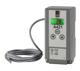
A421 Series Electronic Temperature Control
- parameter adjustment restriction allows you to lock the control’s setup parameters and restrict user adjustments to just the On and Off temperature setpoint values within your defined setpoint adjustment range.
- low- and line-voltage control models provide industry standard control voltage options for most refrigeration and HVAC control applications.
Repair Information
If the A421 Series Electronic Temperature Control fails to operate within its specifications, replace the unit. For a replacement A421 Control, contact the nearest Authorized
Johnson Controls/PENN® Distributer or Sales Representative.
| Single-Stage Electronic Temperature Controls |
A421 Series Electronic Temperature Controls (Continued)
![]()
![]()
![]()
![]()
Selection Chart
A421 Electronic Temperature Control Selection Chart
A99 Temperature Sensors Compatible with the A421 Control1
| Product Code
Number |
Description |
| A99BA-200C | PTC Temperature Sensor: Standard probe 2 in. (5.1 cm) with 6 ft 7-1/5 in. (2.0 m) shielded PVC cable; Ambient operating temperature range: -40 to 212ºF (-40 to 100ºC) |
| A99BB-25C | PTC Temperature Sensor: Standard probe 2 in. (5.1 cm) with 9-7/8 in. (0.25 m) PVC cable; Ambient operating temperature range: -40 to 212ºF (-40 to 100ºC) |
| A99BB-200C | PTC Temperature Sensor: Standard probe 2 in. (5.1 cm) with 6 ft 7-1/5 in. (2.0 m) PVC cable; Ambient operating temperature range: -40 to 212ºF (-40 to 100ºC) |
| A99BB-300C | PTC Temperature Sensor: Standard probe 2 in. (5.1 cm) with 9 ft 9-3/5 in. (3.0 m) PVC cable; Ambient operating temperature range: -40 to 212ºF (-40 to 100ºC) |
| A99BB-400C | PTC Temperature Sensor: Standard probe 2 in. (5.1 cm) with 13 ft 1-1/5 in. (4.0 m) PVC cable; Ambient operating temperature range: -40 to 212ºF (-40 to 100ºC) |
| A99BB-600C | PTC Temperature Sensor: Standard probe 2 in. (5.1 cm) with 19 ft 8-2/5 in. (6.0 m) PVC cable; Ambient operating temperature range: -40 to 212ºF (-40 to 100ºC) |
| A99BC-25C | PTC Temperature Sensor: Standard probe 2 in. (5.1 cm) with 9-7/8 in. (0.25 m) high-temperature silicon cable; Ambient operating temperature range: -40 to 248ºF (-40 to 100ºC) |
| A99BC-100C | PTC Temperature Sensor: Standard probe 2 in. (5.1 cm) with 3 ft 3-3/5 in. (1.0 m) high-temperature silicon cable; Ambient operating temperature range: -40 to 248ºF (-40 to 120ºC) |
| A99BC-300C | PTC Temperature Sensor: Standard probe 2 in. (5.1 cm) with 9 ft 9-3/5 in. (3.0 m) high-temperature silicon cable; Ambient operating temperature range: -40 to 248ºF (-40 to 120ºC) |
| A99BC-500C | PTC Temperature Sensor: Standard probe 2 in. (5.1 cm) with 16 ft 4-4/5 in. (5.0 m) high-temperature silicon cable; Ambient operating temperature range: -40 to 248ºF (-40 to 120ºC) |
| A99BC-1500C | PTC Temperature Sensor: Standard probe 2 in. (5.1 cm) with 49 ft 2-2/5 in. (15.0 m) high-temperature silicon cable; Ambient operating temperature range: -40 to 248ºF (-40 to 120ºC) |
| A99CB-200C | PTC Temperature Sensor: Extended probe 6 in. (15.2 cm) with 6 ft 7-1/5 in. (2.0 m) PVC cable; Ambient operating temperature range: -40 to 212ºF (-40 to 100ºC) |
| A99CB-600C | PTC Temperature Sensor: Extended probe 6 in. (15.2 cm) with 19 ft 8-2/5 in. (6.0 m) PVC cable; Ambient operating temperature range: -40 to 212ºF (-40 to 100ºC) |
1. When any A99 Series Temperature Sensor is connected to a standard temperature A421 Control model, the range of usable values is -40 to 212ºF (-40 to 100ºC).
| Single-Stage Electronic Temperature Controls |
A421 Series Electronic Temperature Controls (Continued)
![]()
![]()
![]()
![]()
Accessories for the A421 Controls
| Product Code
Number |
Description |
| BKT287-1R | 12 in. (305 mm) long DIN rail section |
| BKT287-2R | 36 in. (914 mm) long DIN rail section |
| PLT344-1R | Two End Clamps for DIN rail sections |
| A99-CLP-1 | Surface Mounting Clip for A99B and A99C Series Temperature Sensors |
| SHL10-603R | Sun Shield for A99B and A99C Series Temperature Sensors |
| BOX10A-603R | PVC Enclosure for A99B and A99C Series Temperature Sensors |
| WEL11A-601R | Immersion well for applying sensor in fluid applications |
Technical Specifications
| A421 Series Electronic Temperature Controls | |||||
| Power Consumption | 1.8 VA maximum | ||||
| Supply Power | Low Voltage Models: 24 VAC (20 to 30 VAC), 50/60 Hz, Class 2 or Safety Extra-Low Voltage Line Voltage Models: 110/120 or 208/230/240 VAC, 50/60 Hz | ||||
| Ambient Conditions | Operating: Type 1 Models: -40 to 150°F (-40 to 66°C), 0 to 95% RH Noncondensing Type 4X Models: -40 to 140°F (-40 to 60°C), 0 to 95% RH Noncondensing
Shipping and Storage: -40 to 185°F (-40 to 85°C), 0 to 95% RH Noncondensing |
||||
| Temperature Control Range | -40 to 212°F (-40 to 100°C) | ||||
| Input Signal | 1,035 ohm at 77F (25C) for A99 PTC temperature sensors | ||||
| Sensor Offset Range | ±5ºF or ±3ºC | ||||
| Output Relay Contacts Electrical Ratings | 24 VAC models:
100 VA, 30 VAC maximum, Class 2 |
||||
| 120/240 VAC models: Applied Voltage: Horsepower N.O. (N.C.) :
Full Load Amperes N.O. (N.C.): Locked Rotor Amperes N.O. (N.C.): Resistive Amperes N.O. (N.C.): Pilot Duty N.O. (N.C.): |
24 VAC
— — — 15 (10) A 125 (50) VA |
120 VAC
1 (0.25) hp 16 (5.8) A 96 (34.8) A 15 (10) A 125 (125) VA |
208 VAC
1 (0.33) hp 9.2 (4.0) A 55.2 (24) A 10 (10) A 125 (125) VA |
240 VAC
1 (0.5) hp 8.0 (4.9) A 48 (29.4) A 10 (10) A 125 (125) VA |
|
| Enclosure Material | Type 1/IP20 high-impact thermoplastic or Type 4X/IP66 watertight, corrosion-resistant, high-impact thermoplastic | ||||
| Compliance
|
North America: cULus Listed; UL 60730, File E27734, Vol. 1; FCC Compliant to CFR47, Part 15, Subpart B, Class B Industry Canada (IC) Compliant to Canadian ICES-003, Class B limits
Europe: CE Mark – Johnson Controls, Inc. declares that this product is in compliance with the essential requirements and other relevant provisions of the EMC Directive 2004/108/EC and the Low Voltage Directive 2006/95/EC. Australia: Regulatory Compliance Mark (RCM) |
||||
| Single-Stage Electronic Temperature Controls Code No. LIT-1900934 |
![]()
Description
![]()
![]()
![]()
A421 Series Electronic Temperature Controls with Integral Power Cord
Features
The A421 Series Electronic Temperature Controls are single-stage controls with a single-pole, double-throw (SPDT) output relay, a bright backlit LCD, and a
three-button touchpad interface that can be set up to restrict user adjustments. An LED indicates the output relay’s On/Off status. The A421 Series Controls have simple On and Off temperature settings for heating or cooling, an adjustable anti-short cycle delay, and a temperature offset function.
The control range is -40 to 212°F
(-40 to 100°C) for standard models. Models with a control range of -40 to 248°F
(-40 to 120°C) are available in quantity orders. The controls feature remote sensing capability and interchangeable sensors. The A421 Controls are available in either Type 1 (NEMA)/IP20 high-impact plastic enclosure suitable for surface or DIN rail mounting or Type 4X (NEMA)/IP66 watertight,
corrosion-resistant surface mount enclosures.
The A421ABG Controls Type 1 (NEMA)/IP20 enclosure feature factory-installed power cords with plug and receptacle to provide easy plug-in connection and control of 120 VAC plug-in cooling and heating equipment.
Refer to the A421 Series Electronic Temperature Controls Product Bulletin (LIT-12011972) for important product application information.
Applications
The A421 Electronic Temperature Control can be used to control a wide variety of
single-stage refrigeration or HVAC equipment.
Sample temperature control applications include:
- temperature monitoring and alarming
- on/off control of boilers and chillers
- boiler and chiller pump control
- heating and cooling control
- floating temperature control of damper and valve actuators
- cooling tower fan control based on water temperature
- supply, makeup, and mixed air temperature control
- temperature actuated valve control
- supply and makeup air damper and fan control
- condenser fan control based on condenser temperature
- easy-to-read, bright, adjustable backlit LCD screen displays the temperature, parameters, and status clearly and allows you to adjust LCD brightness for the ambient light conditions. Custom icons on the display provide visual cues on system and control status.
- basic and advanced programming menus allow you to easily set up your control application on the LCD using a simple three-button touchpad interface.
- adjustable On and Off temperature setpoints enable easy to set up cooling or heating control applications on the
three-button touchpad, eliminating the need to remove the cover and reposition jumpers for reverse or direct control actions.
- high and low temperature setpoint adjustment stops allow you to set up your application for your desired range of adjustment and restrict user adjustment to just the desired temperature adjustment range.
- displayed temperature offset allows you to adjust the displayed temperature to the actual sensed temperature in applications where the resistance error in long sensor cable leads cause a deviation in the displayed temperature from the actual sensed temperature.
- adjustable anti-short cycle delay keeps the output relay Off after the Off setpoint is reached for a user-defined time delay, which helps avoid short cycling, hard starts, and nuisance overload outages on compressors and other inductive applications.
- temperature setback/offset control enables the control to shift the On and Off setpoint values by a user-defined offset when an external switch closes the binary input control circuit. Using a switching timer enables you to set up occupied/unoccupied temperature setback schedules for your applications.
- high-impact, thermoplastic Type 1 (NEMA)/IP20 or Type 4X (NEMA)/IP66 watertight, corrosion-resistant enclosures increase application options, allowing surface and snap-fit DIN rail mount, or watertight surface mount.
- parameter adjustment restriction allows you to lock the control’s setup parameters and restrict user adjustments to just the On and Off temperature setpoint values within your defined setpoint adjustment range.
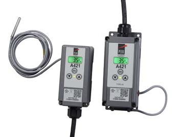
A421 Series Electronic Temperature Controls with Integral Power Cord
- low- and line-voltage control models provide industry standard control voltage options for most refrigeration and HVAC control applications.
Repair Information
If the A421 Series Electronic Temperature Control with Integral Power Cord fails to operate within its specifications, replace the unit. For a replacement A421 Control, contact the nearest Authorized
Johnson Controls/PENN® Distributer or Sales Representative.
| Single-Stage Electronic Temperature Controls |
![]() A421 Series Electronic Temperature Controls with Integral Power Cord (Continued)
A421 Series Electronic Temperature Controls with Integral Power Cord (Continued)
![]()
![]()
![]()
Selection Chart
A421 Electronic Temperature Control Selection Chart
A99 Temperature Sensors Compatible with the A421 Control1
| Product Code Number | Description |
| A99BA-200C | PTC Temperature Sensor: Standard probe 2 in. (5.1 cm) with 6 ft 7-1/5 in. (2.0 m) shielded PVC cable; Ambient operating temperature range: -40 to 212ºF (-40 to 100ºC) |
| A99BB-25C | PTC Temperature Sensor: Standard probe 2 in. (5.1 cm) with 9-7/8 in. (0.25 m) PVC cable; Ambient operating temperature range: -40 to 212ºF (-40 to 100ºC) |
| A99BB-200C | PTC Temperature Sensor: Standard probe 2 in. (5.1 cm) with 6 ft 7-1/5 in. (2.0 m) PVC cable; Ambient operating temperature range: -40 to 212ºF (-40 to 100ºC) |
| A99BB-300C | PTC Temperature Sensor: Standard probe 2 in. (5.1 cm) with 9 ft 9-3/5 in. (3.0 m) PVC cable; Ambient operating temperature range: -40 to 212ºF (-40 to 100ºC) |
| A99BB-400C | PTC Temperature Sensor: Standard probe 2 in. (5.1 cm) with 13 ft 1-1/5 in. (4.0 m) PVC cable; Ambient operating temperature range: -40 to 212ºF (-40 to 100ºC) |
| A99BB-600C | PTC Temperature Sensor: Standard probe 2 in. (5.1 cm) with 19 ft 8-2/5 in. (6.0 m) PVC cable; Ambient operating temperature range: -40 to 212ºF (-40 to 100ºC) |
| A99BC-25C | PTC Temperature Sensor: Standard probe 2 in. (5.1 cm) with 9-7/8 in. (0.25 m) high-temperature silicon cable; Ambient operating temperature range: -40 to 248ºF (-40 to 100ºC) |
| A99BC-100C | PTC Temperature Sensor: Standard probe 2 in. (5.1 cm) with 3 ft 3-3/5 in. (1.0 m) high-temperature silicon cable; Ambient operating temperature range: -40 to 248ºF (-40 to 120ºC) |
| A99BC-300C | PTC Temperature Sensor: Standard probe 2 in. (5.1 cm) with 9 ft 9-3/5 in. (3.0 m) high-temperature silicon cable; Ambient operating temperature range: -40 to 248ºF (-40 to 120ºC) |
| A99BC-500C | PTC Temperature Sensor: Standard probe 2 in. (5.1 cm) with 16 ft 4-4/5 in. (5.0 m) high-temperature silicon cable; Ambient operating temperature range: -40 to 248ºF (-40 to 120ºC) |
| A99BC-1500C | PTC Temperature Sensor: Standard probe 2 in. (5.1 cm) with 49 ft 2-2/5 in. (15.0 m) high-temperature silicon cable; Ambient operating temperature range: -40 to 248ºF (-40 to 120ºC) |
| A99CB-200C | PTC Temperature Sensor: Extended probe 6 in. (15.2 cm) with 6 ft 7-1/5 in. (2.0 m) PVC cable; Ambient operating temperature range: -40 to 212ºF (-40 to 100ºC) |
| A99CB-600C | PTC Temperature Sensor: Extended probe 6 in. (15.2 cm) with 19 ft 8-2/5 in. (6.0 m) PVC cable; Ambient operating temperature range: -40 to 212ºF (-40 to 100ºC) |
1. When any A99 Series Temperature Sensor is connected to a standard temperature A421 control model, the range of usable values is -40 to 212ºF (-40 to 100ºC).
Accessories for the A421 Controls
| Product Code Number | Description |
| BKT287-1R | 12 in. (305 mm) long DIN rail section |
| BKT287-2R | 36 in. (914 mm) long DIN rail section |
| PLT344-1R | Two End Clamps for DIN rail sections |
| A99-CLP-1 | Surface Mounting Clip for A99B and A99C Series Temperature Sensors |
| SHL10-603R | Sun Shield for A99B and A99C Series Temperature Sensors |
| BOX10A-603R | PVC Enclosure for A99B and A99C Series Temperature Sensors |
| WEL11A-601R | Immersion well for applying sensor in fluid applications |
| Single-Stage Electronic Temperature Controls |
![]() A421 Series Electronic Temperature Controls with Integral Power Cord (Continued)
A421 Series Electronic Temperature Controls with Integral Power Cord (Continued)
![]()
![]()
![]()
Technical Specifications
| A421 Series Electronic Temperature Controls | |
| Power Consumption | 1.8 VA maximum |
| Supply Power | 110/120 VAC, 50/60 Hz |
| Ambient Conditions | Operating: Type 1 Models: -40 to 150°F (-40 to 66°C), 0 to 95% RH noncondensing Type 4X Models: -40 to 140°F (-40 to 60°C), 0 to 95% RH noncondensing
Shipping and Storage: All Models: -40 to 185°F (-40 to 85°C), 0 to 95% RH noncondensing |
| Temperature Control Range | -40 to 212°F (-40 to 100°C) |
| Input Signal | 1,035 ohm at 77F (25C) for A99 PTC temperature sensors |
| Sensor Offset Range | ±5ºF or ±3ºC |
| Output Relay Contacts Electrical Ratings | 120 VAC Model with Integral Power Cord:
Applied Voltage: 120 VAC Full Load Amperes N.O.: 12 A Locked Rotor Amperes N.O.: 72 A Resistive Amperes N.O.: 12 A Pilot Duty: 125 VA (N.O. contacts) at 24 to 120 VAC |
| Enclosure Material | NEMA 1/IP20 high-impact thermoplastic or
NEMA 4X/IP66 watertight, corrosion-resistant, high-impact thermoplastic |
| Compliance | North America: cULus Listed; UL 60730, File E27734, Vol. 1; FCC Compliant to CFR47, Part 15, Subpart B, Class B Industry Canada (IC) Compliant to Canadian ICES-003, Class B limits |
| Single-Stage Electronic Temperature Controls Code No. LIT-1900935 |
![]() A421 Series Electronic Temperature Controls with Off-Cycle Defrost
A421 Series Electronic Temperature Controls with Off-Cycle Defrost
![]()
![]()
![]()
Description
The A421 Series Electronic Temperature Controls are single-stage controls with a single-pole, double-throw (SPDT) output relay, a bright backlit LCD, and a
three-button touchpad interface that can be set up to restrict user adjustments. An LED indicates the output relay’s On/Off status. The A421 Series Controls have simple On and Off temperature settings for heating or cooling, an adjustable anti-short cycle delay, and a temperature offset function.
The control range is -40 to 212°F
(-40 to 100°C) for standard models. Models with a control range of -40 to 248°F
(-40 to 120°C) are available in quantity orders. The controls feature remote sensing capability and interchangeable sensors. The A421 Controls are available in either Type 1 (NEMA)/IP20 high-impact plastic enclosure suitable for surface or DIN rail mounting or Type 4X (NEMA)/IP66 watertight,
corrosion-resistant surface mount enclosures.
A421 Controls with Off-Cycle Defrost (A421ABD and A421AED models) provide off-cycle defrost control with
user-configurable defrost cycle duration and frequency.
Refer to the A421 Series Electronic Temperature Controls Product Bulletin (LIT-12011972) for important product application information.
Applications
The A421 Electronic Temperature Control can be used to control a wide variety of
single-stage refrigeration or HVAC equipment.
Sample temperature control applications include:
- temperature monitoring and alarming
- on/off control of boilers and chillers
- boiler and chiller pump control
- heating and cooling control
- floating temperature control of damper and valve actuators
- cooling tower fan control based on water temperature
- supply, makeup, and mixed air temperature control
- temperature actuated valve control
- supply and makeup air damper and fan control
- condenser fan control based on condenser temperature
Features
- easy-to-read, bright, adjustable backlit LCD screen displays the temperature, parameters, and status clearly and allows you to adjust LCD brightness for the ambient light conditions. Custom icons on the display provide visual cues on system and control status.
- basic and advanced programming menus allow you to easily set up your control application on the LCD using a simple three-button touchpad interface.
- adjustable On and Off temperature setpoints enable easy to set up cooling or heating control applications on the
three-button touchpad, eliminating the need to remove the cover and reposition jumpers for reverse or direct control actions.
- high and low temperature setpoint adjustment stops allow you to set up your application for your desired range of adjustment and restrict user adjustment to just the desired temperature adjustment range.
- displayed temperature offset allows you to adjust the displayed temperature to the actual sensed temperature in applications where the resistance error in long sensor cable leads cause a deviation in the displayed temperature from the actual sensed temperature.
- adjustable anti-short cycle delay keeps the output relay Off after the Off setpoint is reached for a user-defined time delay, which helps avoid short cycling, hard starts, and nuisance overload outages on compressors and other inductive applications.
- integrated off-cycle defrost timer (defrost control models only) shuts off the refrigeration system for a user-defined defrost time interval at a user-defined frequency. This eliminates the cost and time to install a separate defrost timer in many refrigeration applications.
- temperature setback/offset control enables the control to shift the On and Off setpoint values by a user-defined offset when an external switch closes the binary input control circuit. Using a switching timer enables you to set up occupied/unoccupied temperature setback schedules for your applications.
- high-impact, thermoplastic Type 1 (NEMA)/IP20 or Type 4X (NEMA)/IP66 watertight, corrosion-resistant enclosures increase application options, allowing surface and snap-fit DIN rail mount, or watertight surface mount.
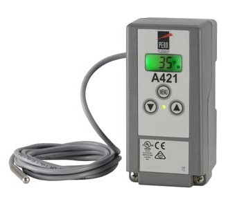
A421 Series Electronic Temperature Control with Off-Cycle Defrost
- parameter adjustment restriction allows you to lock the control’s setup parameters and restrict user adjustments to just the On and Off temperature setpoint values within your defined setpoint adjustment range.
- low- and line-voltage control models provide industry standard control voltage options for most refrigeration and HVAC control applications.
Repair Information
If the A421 Series Electronic Temperature Control with Off-Cycle Defrost fails to operate within its specifications, replace the unit. For a replacement A421 Control, contact the nearest Johnson Controls® representative.
| Single-Stage Electronic Temperature Controls |
![]() A421 Series Electronic Temperature Controls with Off-Cycle Defrost (Continued)
A421 Series Electronic Temperature Controls with Off-Cycle Defrost (Continued)
![]()
![]()
![]()
Selection Charts
A421 Electronic Temperature Controls
A99 Temperature Sensors Compatible with the A421 Control1
| Product Code Number | Description |
| A99BA-200C | PTC Temperature Sensor: Standard probe 2 in. (5.1 cm) with 6 ft 7-1/5 in. (2.0 m) shielded PVC cable; Ambient operating temperature range: -40 to 212ºF (-40 to 100ºC) |
| A99BB-25C | PTC Temperature Sensor: Standard probe 2 in. (5.1 cm) with 9-7/8 in. (0.25 m) PVC cable; Ambient operating temperature range: -40 to 212ºF (-40 to 100ºC) |
| A99BB-200C | PTC Temperature Sensor: Standard probe 2 in. (5.1 cm) with 6 ft 7-1/5 in. (2.0 m) PVC cable; Ambient operating temperature range: -40 to 212ºF (-40 to 100ºC) |
| A99BB-300C | PTC Temperature Sensor: Standard probe 2 in. (5.1 cm) with 9 ft 9-3/5 in. (3.0 m) PVC cable; Ambient operating temperature range: -40 to 212ºF (-40 to 100ºC) |
| A99BB-400C | PTC Temperature Sensor: Standard probe 2 in. (5.1 cm) with 13 ft 1-1/5 in. (4.0 m) PVC cable; Ambient operating temperature range: -40 to 212ºF (-40 to 100ºC) |
| A99BB-600C | PTC Temperature Sensor: Standard probe 2 in. (5.1 cm) with 19 ft 8-2/5 in. (6.0 m) PVC cable; Ambient operating temperature range: -40 to 212ºF (-40 to 100ºC) |
| A99BC-25C | PTC Temperature Sensor: Standard probe 2 in. (5.1 cm) with 9-7/8 in. (0.25 m) high-temperature silicon cable; Ambient operating temperature range: -40 to 248ºF (-40 to 100ºC) |
| A99BC-100C | PTC Temperature Sensor: Standard probe 2 in. (5.1 cm) with 3 ft 3-3/5 in. (1.0 m) high-temperature silicon cable; Ambient operating temperature range: -40 to 248ºF (-40 to 120ºC) |
| A99BC-300C | PTC Temperature Sensor: Standard probe 2 in. (5.1 cm) with 9 ft 9-3/5 in. (3.0 m) high-temperature silicon cable; Ambient operating temperature range: -40 to 248ºF (-40 to 120ºC) |
| A99BC-500C | PTC Temperature Sensor: Standard probe 2 in. (5.1 cm) with 16 ft 4-4/5 in. (5.0 m) high-temperature silicon cable; Ambient operating temperature range: -40 to 248ºF (-40 to 120ºC) |
| A99BC-1500C | PTC Temperature Sensor: Standard probe 2 in. (5.1 cm) with 49 ft 2-2/5 in. (15.0 m) high-temperature silicon cable; Ambient operating temperature range: -40 to 248ºF (-40 to 120ºC) |
| A99CB-200C | PTC Temperature Sensor: Extended probe 6 in. (15.2 cm) with 6 ft 7-1/5 in. (2.0 m) PVC cable; Ambient operating temperature range: -40 to 212ºF (-40 to 100ºC) |
| A99CB-600C | PTC Temperature Sensor: Extended probe 6 in. (15.2 cm) with 19 ft 8-2/5 in. (6.0 m) PVC cable; Ambient operating temperature range: -40 to 212ºF (-40 to 100ºC) |
1. When any A99 Series Temperature Sensor is connected to a standard temperature A421 control model, the range of usable values is -40 to 212ºF (-40 to 100ºC).
Accessories for the A421 Controls
| Product Code Number | Description |
| BKT287-1R | 12 in. (305 mm) long DIN Rail section |
| BKT287-2R | 36 in. (914 mm) long DIN Rail section |
| PLT344-1R | Two End Clamps for DIN Rail sections |
| A99-CLP-1 | Surface Mounting Clip for A99B and A99C Series Temperature Sensors |
| SHL10-603R | Sun Shield for A99B and A99C Series Temperature Sensors |
| BOX10A-603R | PVC Enclosure for A99B and A99C Series Temperature Sensors |
| WEL11A-601R | Immersion Well for applying sensor in fluid applications |
| Single-Stage Electronic Temperature Controls |
![]() A421 Series Electronic Temperature Controls with Off-Cycle Defrost (Continued)
A421 Series Electronic Temperature Controls with Off-Cycle Defrost (Continued)
![]()
![]()
![]()
Technical Specifications
| A421 Series Electronic Temperature Controls | |
| Power Consumption | 1.8 VA Maximum |
| Supply Power | 24 VAC, 50/60 Hz, Class 2:
108/110/115/120 or 208/230/240 VAC, 50/60 Hz |
| Ambient Conditions | Operating: -40 to 150°F (-40 to 66°C), 0 to 95% RH Noncondensing
Shipping and Storage: -40 to 185°F (-40 to 85°C), 0 to 95% RH Noncondensing |
| Temperature Control Range | -40 to 212°F (-40 to 100°C) or -40 to 248ºF (-40 to 120ºC), depending on the model selected |
| Input Signal | 1,035 ohm at 77F (25C) for A99 PTC temperature sensors |
| Sensor Offset Range | ±5ºF or ±3ºC |
| Output Relay Contacts Electrical Ratings | 24 VAC Models:
100 VA, 30 VAC maximum, Class 2 |
| 120 VAC Model with Integral Power Cord: Applied Voltage: 120 VAC Full Load Amperes N.O. and N.C.: 12 A Locked Rotor Amperes N.O. and N.C.: 72 A Non-inductive Amperes N.O. and N.C.:12 A
Pilot Duty: 125 VA (N.O. contacts) at 24 to 120 VAC |
|
| 120/240 VAC Models:
Applied Voltage: 120 VAC 208 VAC 240 VAC Horsepower N.O. (N.C.) : 1 (0.25) hp 1 (0.33) hp 1 (0.5) hp Full Load Amperes N.O. (N.C.): 16 (5.8) A 9.2 (4.0) A 8.0 (4.9) A Locked Rotor Amperes N.O. (N.C.): 96 (34.8) A 55.2 (24) A 48 (29.4) A Non-inductive Amperes N.O. (N.C.):15 (10) A 10 (10) A 10 (10) A Pilot Duty: 125 VA (N.O. contacts) at 24 to 240 VAC 125 VA (N.C. contacts) at 24 to 240 VAC 50 VA (N.C. contacts) at 24 VAC |
|
| Enclosure Material | NEMA 1/IP20 High-Impact Thermoplastic or
NEMA 4X/IP66 Watertight, Corrosion-Resistant, High-Impact Thermoplastic |
| Compliance
|
North America: cULus Listed; UL 60730, File E27734, Vol. 1; FCC Compliant to CFR47, Part 15, Subpart B, Class B Industry Canada (IC) Compliant to Canadian ICES-003, Class B limits
Europe: CE Mark – Johnson Controls, Inc. declares that this product is in compliance with the essential requirements and other relevant provisions of the EMC Directive 2004/108/EC and the Low Voltage Directive 2006/95/EC. Australia: Mark: C-Tick Compliant (N1813) |
| Single-Stage Electronic Temperature Controls Code No. LIT-1900936 |
![]()
Description
![]()
![]()
![]()
A421 Series Electronic Temperature Controls with Integral Cycle Timer
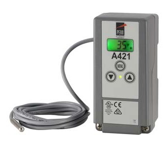 Features
The A421 Series Electronic Temperature Controls are single-stage controls with a single-pole, double-throw (SPDT) output relay, a bright backlit LCD, and a
three-button touchpad interface that can be set up to restrict user adjustments. An LED indicates the output relay’s On/Off status. The A421 Series Controls have simple On and Off temperature settings for heating or cooling, an adjustable anti-short cycle delay, and a temperature offset function.
The control range is -40 to 212°F
(-40 to 100°C) for standard models. Models with a control range of -40 to 248°F
(-40 to 120°C) are available in quantity orders. The controls feature remote sensing capability and interchangeable sensors. The
A421 Controls are available in either Type 1 (NEMA)/IP20 high-impact plastic enclosure suitable for surface or DIN rail
mounting or Type 4X (NEMA)/IP66 watertight, corrosion-resistant surface mount enclosures.
The A421 Controls with Integral Cycle Timer provide On/Off control of ventilation fans in agriculture applications, warehouse and storage facilities, and other ventilation application that require air-exchange based on temperature or a ventilation schedule with a user-defined On-time and Off-time cycle.
Refer to the A421 Series Electronic Temperature Controls Product Bulletin (LIT-12011972) for important product application information.
Applications
The A421 Electronic Temperature Control can be used to control a wide variety of
single-stage refrigeration or HVAC equipment.
Sample temperature control applications include:
- temperature monitoring and alarming
- on/off control of boilers and chillers
- boiler and chiller pump control
- heating and cooling control
- floating temperature control of damper and valve actuators
- cooling tower fan control based on water temperature
- supply, makeup, and mixed air temperature control
- temperature actuated valve control
- supply and makeup air damper and fan control
- condenser fan control based on condenser temperature
- easy-to-read, bright, adjustable backlit LCD screen displays the temperature, parameters, and status clearly and allows you to adjust LCD brightness for the ambient light conditions. Custom icons on the display provide visual cues on system and control status.
- basic and advanced programming menus allow you to easily set up your control application on the LCD using a simple three-button touchpad interface.
- adjustable On and Off temperature setpoints enable easy to set up cooling or heating control applications on the
three-button touchpad, eliminating the need to remove the cover and reposition jumpers for reverse or direct control actions.
- high and low temperature setpoint adjustment stops allow you to set up your application for your desired range of adjustment and restrict user adjustment to just the desired temperature adjustment range.
- displayed temperature offset allows you to adjust the displayed temperature to the actual sensed temperature in applications where the resistance error in long sensor cable leads cause a deviation in the displayed temperature from the actual sensed temperature.
- adjustable anti-short cycle delay keeps the output relay Off after the Off setpoint is reached for a user-defined time delay, which helps avoid short cycling, hard starts, and nuisance overload outages on compressors and other inductive applications.
- temperature and timed ventilation control (integral cycle timer models only) enables you to set up timed ventilation or makeup air cycles independent from temperature controlled cycles. This eliminates the cost and time to install a separate interval timer in ventilation and makeup air applications.
- temperature setback/offset control enables the control to shift the On and Off setpoint values by a user-defined offset when an external switch closes the binary input control circuit. Using a switching timer enables you to set up occupied/unoccupied temperature setback schedules for your applications.
- high-impact, thermoplastic NEMA 1/IP20 or NEMA 4X/IP66 watertight,
corrosion-resistant enclosures increase application options, allowing surface and snap-fit DIN rail mount, or watertight surface mount.
A421 Series Electronic Temperature Control with Integral Cycle Timer
- parameter adjustment restriction allows you to lock the control’s setup parameters and restrict user adjustments to just the On and Off temperature setpoint values within your defined setpoint adjustment range.
- low- and line-voltage control models provide industry standard control voltage options for most refrigeration and HVAC control applications.
Repair Information
If the A421 Series Electronic Temperature Control with Integral Cycle Timer fails to operate within its specifications, replace the unit. For a replacement A421 Control, contact the nearest Johnson Controls® representative.
| Single-Stage Electronic Temperature Controls |
![]() A421 Series Electronic Temperature Controls with Integral Cycle Timer (Continued)
A421 Series Electronic Temperature Controls with Integral Cycle Timer (Continued)
![]()
![]()
![]()
Selection Charts
A421 Electronic Temperature Controls
A99 Temperature Sensors Compatible with the A421 Control1
| Product Code Number | Description |
| A99BA-200C | PTC Temperature Sensor: Standard probe 2 in. (5.1 cm) with 6 ft 7-1/5 in. (2.0 m) shielded PVC cable; Ambient operating temperature range: -40 to 212ºF (-40 to 100ºC) |
| A99BB-25C | PTC Temperature Sensor: Standard probe 2 in. (5.1 cm) with 9-7/8 in. (0.25 m) PVC cable; Ambient operating temperature range: -40 to 212ºF (-40 to 100ºC) |
| A99BB-200C | PTC Temperature Sensor: Standard probe 2 in. (5.1 cm) with 6 ft 7-1/5 in. (2.0 m) PVC cable; Ambient operating temperature range: -40 to 212ºF (-40 to 100ºC) |
| A99BB-300C | PTC Temperature Sensor: Standard probe 2 in. (5.1 cm) with 9 ft 9-3/5 in. (3.0 m) PVC cable; Ambient operating temperature range: -40 to 212ºF (-40 to 100ºC) |
| A99BB-400C | PTC Temperature Sensor: Standard probe 2 in. (5.1 cm) with 13.1 ft (4.0 m) PVC cable; Ambient operating temperature range: -40 to 212ºF (-40 to 100ºC) |
| A99BB-600C | PTC Temperature Sensor: Standard probe 2 in. (5.1 cm) with 19 ft 8-2/5 in. (6.0 m) PVC cable; Ambient operating temperature range: -40 to 212ºF (-40 to 100ºC) |
| A99BC-25C | PTC Temperature Sensor: Standard probe 2 in. (5.1 cm) with 9-7/8 in. (0.25 m) high-temperature silicon cable; Ambient operating temperature range: -40 to 248ºF (-40 to 100ºC) |
| A99BC-100C | PTC Temperature Sensor: Standard probe 2 in. (5.1 cm) with 3 ft 3-3/5 in. (1.0 m) high-temperature silicon cable; Ambient operating temperature range: -40 to 248ºF (-40 to 120ºC) |
| A99BC-300C | PTC Temperature Sensor: Standard probe 2 in. (5.1 cm) with 9 ft 9-3/5 in. (3.0 m) high-temperature silicon cable; Ambient operating temperature range: -40 to 248ºF (-40 to 120ºC) |
| A99BC-500C | PTC Temperature Sensor: Standard probe 2 in. (5.1 cm) with 16 ft 4-4/5 in. (5.0 m) high-temperature silicon cable; Ambient operating temperature range: -40 to 248ºF (-40 to 120ºC) |
| A99BC-1500C | PTC Temperature Sensor: Standard probe 2 in. (5.1 cm) with 49 ft 2-2/5 in. (15.0 m) high-temperature silicon cable; Ambient operating temperature range: -40 to 248ºF (-40 to 120ºC) |
| A99CB-200C | PTC Temperature Sensor: Extended probe 6 in. (15.2 cm) with 6 ft 7-1/5 in. (2.0 m) PVC cable; Ambient operating temperature range: -40 to 212ºF (-40 to 100ºC) |
| A99CB-600C | PTC Temperature Sensor: Extended probe 6 in. (15.2 cm) with 19 ft 8-2/5 in. (6.0 m) PVC cable; Ambient operating temperature range: -40 to 212ºF (-40 to 100ºC) |
1. When any A99 Series Temperature Sensor is connected to a standard temperature A421 control model, the range of usable values is -40 to 212ºF (-40 to 100ºC).
Accessories for the A421 Controls
| Product Code Number | Description |
| BKT287-1R | 12 in. (305 mm) long DIN rail section |
| BKT287-2R | 36 in. (914 mm) long DIN rail section |
| PLT344-1R | Two End Clamps for DIN rail sections |
| A99-CLP-1 | Surface Mounting Clip for A99B and A99C Series Temperature Sensors |
| SHL10-603R | Sun Shield for A99B and A99C Series Temperature Sensors |
| BOX10A-603R | PVC Enclosure for A99B and A99C Series Temperature Sensors |
| WEL11A-601R | Immersion well for applying sensor in fluid applications |
| Single-Stage Electronic Temperature Controls |
![]() A421 Series Electronic Temperature Controls with Integral Cycle Timer (Continued)
A421 Series Electronic Temperature Controls with Integral Cycle Timer (Continued)
![]()
![]()
![]()
Technical Specifications
| A421 Series Electronic Temperature Controls | |
| Power Consumption | 1.8 VA maximum |
| Supply Power | 24 VAC, 50/60 Hz, Class 2:
108/110/115/120 or 208/230/240 VAC, 50/60 Hz |
| Ambient Conditions | Operating: -40 to 150°F (-40 to 66°C), 0 to 95% RH noncondensing
Shipping and Storage: -40 to 185°F (-40 to 85°C), 0 to 95% RH noncondensing |
| Temperature Control Range | -40 to 212°F (-40 to 100°C) or -40 to 248ºF (-40 to 120ºC), depending on the model selected |
| Input Signal | 1,035 ohms at 77F (25C) for A99 PTC temperature sensors |
| Sensor Offset Range | ±5ºF or ±3ºC |
| Output Relay Contacts Electrical Ratings | 24 VAC Models:
100 VA, 30 VAC maximum, Class 2 |
| 120 VAC Model with Integral Power Cord: Applied Voltage: 120 VAC Full Load Amperes N.O. and N.C.: 12 A Locked Rotor Amperes N.O. and N.C.: 72 A Non-inductive Amperes N.O. and N.C.:12 A
Pilot Duty: 125 VA (N.O. contacts) at 24 to 120 VAC |
|
| 120/240 VAC Models:
Applied Voltage: 120 VAC 208 VAC 240 VAC Horsepower N.O. (N.C.) : 1 (0.25) hp 1 (0.33) hp 1 (0.5) hp Full Load Amperes N.O. (N.C.): 16 (5.8) A 9.2 (4.0) A 8.0 (4.9) A Locked Rotor Amperes N.O. (N.C.): 96 (34.8) A 55.2 (24) A 48 (29.4) A Non-inductive Amperes N.O. (N.C.):15 (10) A 10 (10) A 10 (10) A Pilot Duty: 125 VA (N.O. contacts) at 24 to 240 VAC 125 VA (N.C. contacts) at 24 to 240 VAC 50 VA (N.C. contacts) at 24 VAC |
|
| Enclosure Material | NEMA 1/IP20 high-impact thermoplastic or
NEMA 4X/IP66 watertight, corrosion-resistant, high-impact thermoplastic |
| Compliance
|
North America: cULus Listed; UL 60730, File E27734, Vol. 1; FCC Compliant to CFR47, Part 15, Subpart B, Class B Industry Canada (IC) Compliant to Canadian ICES-003, Class B limits
Europe: CE Mark – Johnson Controls, Inc. declares that this product is in compliance with the essential requirements and other relevant provisions of the EMC Directive 2004/108/EC and the Low Voltage Directive 2006/95/EC. Australia: Mark: C-Tick Compliant (N1813) |
| Single-Stage Electronic Temperature Controls Code No. LIT-1900003 |
![]() MR Series Defrost Control Modules
MR Series Defrost Control Modules
![]()
![]()
![]()
Description
The MR Series Controls are versatile, microprocessor-based, multifunction, programmable temperature controls. Depending on the model chosen, the
MR Series Controls can also manage alarm, defrost cycle (active or passive defrost), and evaporator fan functions.
The MR Series Controls have large red LED displays. These compact controls are available in panel mount and DIN rail mount varieties. The MR Series Controls use the A99B temperature sensors, which allow remote mounting of the display unit.
All MR Series Controls perform temperature and alarm management. Some models have additional capabilities.
MR1 Series Controls
The MR1 Series provides temperature and alarm management functions. It can replace a temperature control and digital temperature readout.
MR2 Series Controls
The MR2 Series provides temperature, alarm, and defrost cycle management. The MR2 control performs defrost cycle management using time-based, passive, off cycle defrost. It can replace a temperature control, a digital temperature readout, and a defrost timer.
Refer to the MR Series Refrigeration Temperature Controls Product Bulletin (LIT-125199) for important product application information.
Applications
MR4 Series Controls
The MR4 Series provides temperature, alarm, defrost, and evaporator fan management.
The MR4 Series provides defrost cycle management with hot gas or electric heat defrost and defrost termination based on time or temperature. The MR4 Series consolidates the functions of a temperature control, a digital temperature readout, a defrost cycle timer, and a defrost termination device.
Refer to the MR Series Refrigeration Temperature Controls Product Bulletin (LIT-125199) for important product application information.
Features
- programmable functions allow adjustment of control settings to meet application needs
- alarm management functions provide local alarm display and an alarm output relay that can be used to trigger a remote alarm or dial-out modem
- easily readable LED display displays temperature and other functions quickly and clearly
- programming button lockout allows user to disable programming buttons and deter accidental or unauthorized changes
- accurate, interchangeable temperature sensor provides accurate control performance with up to 300 feet of wiring (an adjustable temperature offset is provided for longer wiring)
- self-test procedure checks control operation by cycling all outputs and testing all LEDs
Selection Chart
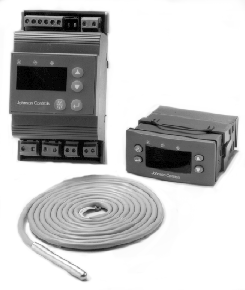
MR4 Series
DIN Rail and Panel Mount Modules
Repair Information
If the MR Series Defrost Control Modules fails to operate within its specifications, replace the unit. For a replacement control, contact the nearest Johnson Controls® representative.
| Application | MR1 | MR2 | MR4 |
| Cooling tower pump control | | ||
| Space and return air temperature control | | ||
| Convenience store coolers | | | |
| Convenience store freezers | | ||
| Supermarket display cases for produce | | | |
| Reach-in coolers | | | |
| Walk-in coolers | | | |
| Freezers or coolers with passive defrost, time-based termination | | | |
| Freezers with hot gas defrost (temperature or time-based termination | | ||
| Freezers with electrical defrost (temperature or time-based termination) | |
Single-Stage Electronic Temperature Controls
MR Series Defrost Control Modules (Continued)
![]()
![]()
![]()
![]()
Technical Specifications
| MR Series Defrost Control Modules | ||
| Power Requirements | 24 VAC, 50/60 Hz Class 2 (20 to 30 VAC) | |
| Power Consumption | 3.7 VA at 24 VAC | |
| Accuracy | ± 1.8F° (± 1°C) | |
| Ambient Conditions | Operating | +14 to +140°F (-10 to +60°C); 0 to 95% RH (noncondensing) |
| Storage | -22 to +176°F (-30 to +80°C); 0 to 95% RH (noncondensing) | |
| Dimensions (H x W x D) | Panel Mount | 1.38 x 2.95 x 2.68 in. (35 x 75 x 68 mm) |
| DIN Rail: | 4.65 x 2.76 x 2.07 in. (118 x 70 x 53 mm) | |
| Agency Listings | UL Recognized: File E194024, CCN XAPX2
Canadian UL Recognized: File E194024, CCN XAPX8 |
|
Electrical Ratings of Contacts
| Rating Category | 120 VAC | 240 VAC | 24 VDC |
| Horsepower | 1/4 | 1/2 | — |
| Full Load Amperes | 5.8 | 4.9 | — |
| Locked Rotor Amperes | 34.8 | 29.4 | — |
| Inductive (Non-Motor) Amperes | 8 | 8 | 8 |
| Pilot Duty VA | 275 | 450 | — |
Note: Relay outputs must not exceed 20 Amperes total connected load. Open collector transistors on MR1 alarms have a maximum rating of 40 VDC 100 mA. Alarms require external power source.
Refer to Rating Table for more information
Internal to Control
Process Temperature Sensor
Sensor
Common
Binary Input
Binary Common
Evaporator Alarm Temperature
Sensor
Internal to Control
Power Compressor
Supply
Evaporator
Fan
Defrost
Refer to Rating Table for more information
S1
SC
D
CD
S2
A1
A2
Terminal Not Used
V1
V2
C1
Fr
C3
Fn
C2
Df
![]()
![]()
![]()
![]()
![]()
![]()
![]()
![]()
![]()
![]()
![]()
Common
C
Fr
A1
Df
Fn
V1
V2
D
Defrost
Power Binary
Sensor
S1
SC
S2
Alarm Compressor
mr4panel.eps
Supply
Evaporator Input
Fan
Common
Evaporator Temperature
MR4 DIN Rail Control
mr4dinrl.eps
Process Temperature Sensor
MR4 Panel Mount Control
Sensor
| Single-Stage Electronic Temperature Controls Code No. LIT-1927380 |
 MR4PMUHV Electronic Temperature/Defrost Control with Relay Pack
![]()
![]()
![]()
Description
The MR Series temperature controls are designed for use with hot gas or electric heat defrost in both refrigeration and freezer units. Either time or temperature based defrost termination may be selected.
The MR Series incorporates control functions such as compressor control, defrost management, fan management, and alarm management.
Refer to the MR4PMUHV Electronic Temperature/Defrost Control with Relay Pack Product Bulletin (LIT-125190) for important product application information.
Features
- single package provides the functionality of multiple components at a cost-effective price
- mounting flexibility allows the control and relay pack to be mounted together or separately, facilitating multiple configurations
- accurate, interchangeable temperature sensor provides reliable control performance with up to 300 ft. of wiring (an offset is provided for longer wiring)
- easily readable temperature display can show either evaporator or process temperature at the touch of a button
- heavy-duty relays allow direct control of compressors, fans, defrost heaters, and alarms
- alarm management functions provide both local alarm codes and a relay closure that can be used to trigger a remote alarm or a dial-out modem
Applications
These relay pack mounted controls provide direct control of compressors up to 2 hp, electric heater loads of up to 20 amperes, and evaporator fan loads of up to 3/4 hp. The need for separate relays is eliminated in these applications.
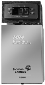
MR4PMUHV Temperature Control
In addition, the MR4PMUHV controls combine the functionality of an electromechanical thermostat, mechanical clock, defrost termination device, and temperature readout device with the accuracy of electronic technology.
MR4PMUHV Electronic Temperature/Defrost Control with Relay Pack
| Product Code Number | Description |
| MR4PMUHV-12C | Relay pack defrost control with two
A99BB-200C sensors |
Repair Parts
| Product Code Number | Description |
| MR4PM12C-12C | Replacement control for use in relay pack |
| RP4MRUHV-1C | Relay pack without control |
| A99BB-200C | Sensor, cable length: 6.5 ft/1.98m |
Technical Specifications
| MR4PMUHV Electronic Temperature/Defrost Control
with Relay Pack (Part 1 of 2) |
||
| Frequency | 60/50 Hz at 120/240 VAC | |
| Power consumption | 10 VA at 240 VAC, 5 VA at 120 VAC | |
| Supply Level | 120 and L1: 120 VAC +10%/-15%
240 and L1: 240 VAC +10%/-15% |
|
| Accuracy | ± 1.8F°/± 1C° | |
| A99 Sensor Cable | 6.5 ft/1.98 m | |
| Ambient Operating Conditions | MR4PMUHV-12C | +14° to +111°F/-10° to +44°C;
derating 6.25% per 1°C to 60° C; 0 to 95% RH (noncondensing) |
| MR4PM12C-12C | +14° to +140°F/-10° to +60°C;
0 to 95% RH (noncondensing) |
|
| RP4MRUHV-1C | -40° to +111°F/ -40° to +44°C;
derating 6.25% per 1°C to 60° C; 0 to 95% RH (noncondensing) |
|
| Ambient Storage Conditions | MR4PMUHV-12C | -22° to +176°F/-30° to +80°C
0 to 95% RH (noncondensing) |
| MR4PM12C-12C | -22° to +176°F/-30° to +80°C
0 to 95% RH (noncondensing) |
|
| RP4MRUHV-1C | -40° to +185°F/-40° to +85°C
0 to 95% RH (noncondensing) |
|
| Dimensions (H x W x D) | 7.94 x 3.6 x 2.4 in./202 x 92 x 61 mm | |
Technical Specifications (Continued)
| MR4PMUHV Electronic Temperature/Defrost Control
with Relay Pack (Part 2 of 2) |
|
| Agency Listings | UL Listed (File SA516, UL Guide SDFY;
cUL Guide SDFY7) |
| Shipping Weight | 2.9 lb/1,320 g |
Relay Electrical Ratings
| 24 | 120 | 208 | 240 | |
| SPST Compressor Relay | ||||
| Horsepower Rating | — | 1 | 1.5 | 2 |
| AC Full Load Amperes | — | 16 | 11 | 12 |
| AC Locked Rotor Amperes | — | 96 | 66 | 72 |
| Pilot Duty (VA) | 125 | 750 | 875 | 1,125 |
| SPDT Fan Relay | ||||
| Horsepower Rating | — | 1/3 | 1/2 | 3/4 |
| AC Full Load Amperes | — | 7.2 | 5.65 | 6.9 |
| AC Locked Rotor Amperes | — | 43.2 | 33.9 | 41.4 |
| Pilot Duty (VA) | 50 | 325 | 450 | 600 |
| SPST Defrost Heater Relay | ||||
| Horsepower Rating | — | 1 | 1.5 | 2 |
| AC Full Load Ampere | — | 16 | 11 | 12 |
| AC Locked Rotor Amperes | — | 96 | 66 | 72 |
| Non-Inductive Load Amperes | — | 20 | 20 | 20 |
| Pilot Duty (VA) | 125 | 750 | 825 | 1,125 |
| SPST Alarm Relay | ||||
| Non-Inductive Load Ampere | 5 | 5 | 5 | 5 |
| Pilot Duty (VA) | — | 125 | 250 | 325 |
Relay Electrical Ratings Note:
Ratings shown are for ambient operation at -40 to 44°C. Derate electrical ratings 6.25% per 1°C (1.8°F) between 44°C (111°F) and 60°C (140°F).
Multi-Stage Electromechanical Temperature Controls Code No. LIT-1927110
 A28 Series Two-Stage Temperature Control
![]()
![]()
![]()
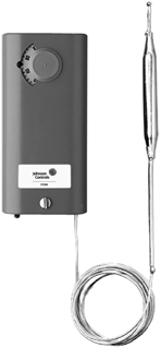 Description
The A28 Series are two-stage temperature controls that incorporate a liquid-filled sensing element.
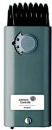 Refer to the A28 Series Two-Stage Temperature Controls with NEMA 1 Enclosure Product Bulletin Product Bulletin (LIT-125130) for important product application information.
A28 Series
Action on Increase of Temperature
A28 Action Diagram
A28AA-4
Temperature Control
![]()
![]()
![]()
![]()
![]()
![]()
![]()
![]()
Y
R
B
High Stage
Y
R
B
Low Stage
a28.eps
Applications
A28AB-29
Temperature Control
Features
- wide temperature ranges available
- constant differential throughout the entire range
- single-pole, double-throw (SPDT) snap-acting switches
- unaffected by changes in barometric pressure
- unaffected by cross ambient conditions
- compact enclosure
- variety of sensing element styles
Selection Charts
Use for temperature sensing applications requiring two-stage control of HVAC/R equipment.
Accessories
- packing nut assembly available for direct immersion applications (Code No. FTG13A-600R)
- remote bulb models include 5/8 in. mounting clip
| Product Code
Number |
Switch
Action |
Range
°F (°C) |
Differential
F° (C°) |
Bulb and
Capillary |
Bulb Well No.
(Order Separately) |
Range
Adjuster |
| Coiled Bulb-Fixed Differential | ||||||
| A28AA-4C | Two-SPDT | 30 to 110
(-1 to 43) |
3-1/2 (1.9) each stage
3 (1.7) fixed between stages |
1-3/8 in. x 2-1/4 in.
coiled |
– | Convertible |
| Case Compensated-Fixed Differential | ||||||
| A28AA-9C | Two-SPDT | 20 to 80
(-7 to 27) |
3-1/2 (1.9) each stage
3 (1.7) fixed between stages |
3/8 in. x 5 in. 6 ft capillary1 | WEL14A-603R | Knob |
| Wide Range-Adjustable Interstage Differential | ||||||
| A28AA-28C | Two-SPDT | 30 to 110 | 3-1/2 (1.9) each stage
2 to 7 adjustable between stages |
12 ft averaging bulb
6 ft capillary |
– | Screwdriver |
| A28AA-29C | Two-SPDT | -30 to 100 | 5 (2.8) each stage
2 to 7 adjustable between stages |
3/8 in. x 4 in. 8 ft capillary1 | WEL14A-602R | Convertible |
| A28AA-36C | Two-SPDT | 40 to 90 | 3 each stage
2 to 7 adjustable between stages |
3/8 in. x 5-3/4 in. 6 ft capillary | – | Knob |
| A28AA-37C | Two-SPDT | 60 to 140 | 5 each stage
2 to 7 adjustable between stages |
3/8 in. x 4 in. 6 ft capillary | WEL14A-602R | Knob |
| A28AJ-4C | Two-SPDT | 20 to 80
(-7 to 27) |
2 each stage
2 to 7 adjustable between stages |
3/16 in. x 22 in. 6 ft capillary | – | Knob |
| Changeover Control | ||||||
| A28AB-1C | Two-SPDT2 | 20 to 80
(-7 to 27) |
3-1/2
(1.9) |
3/8 in. x 5 in.
6 ft capillary |
WEL14A-603R | Screwdriver
slot |
- Packing nut assembly available for direct immersion applications (Code No. FTG13A-600R).
- Switches within 1 F° (0.6 C°) of each other.
| Multi-Stage Electromechanical Temperature Controls |
A28 Series Two-Stage Temperature Control (Continued)
![]()
![]()
![]()
![]()
Replacement Parts
| Product Code Number | Description |
| CVR28A-617R | Concealed adjustment |
| CVR28A-618R | Visible scale |
| KNB20A-602R | Knob kit |
Technical Specifications
Maximum bulb temperature of A28AA-37 is 230°F (110°C). For all others, maximum bulb temperature is 140°F (60°C).
Electrical Ratings
| Motor Ratings VAC | 120 | 208 | 240 | 277 |
| A28AA, A | ||||
| AC Full Load A | 16.0 | 9.2 | 8.0 | — |
| AC Locked Rotor A | 96.0 | 55.2 | 48.0 | — |
| Non-Inductive or Resistance Load A (Not Lamp Loads) | 16.0 | 9.2 | 8.0 | 7.2 |
| Pilot Duty | 125 VA, 24 to 277 VAC1 | |||
| A28AJ | ||||
| AC Full Load A | 6.0 | 3.4 | 3.0 | — |
| AC Locked Rotor A | 36.0 | 20.4 | 18.0 | — |
| Non-Inductive or Resistance Load A (Not Lamp Loads) | 15.0 | 9.2 | 8.0 | 7.2 |
| Pilot Duty | 125 VA, 24 to 277 VAC1 | |||
| A28AB | ||||
| AC Full Load A | 16.0 | 9.2 | 8.0 | — |
| AC Locked Rotor A | 96.0 | 55.2 | 48.0 | — |
| Non-Inductive or Resistance Load A (Not Lamp Loads) | 16.0 | 9.2 | 8.0 | 7.2 |
| Pilot Duty | 125 VA, 24 to 277 VAC1 | |||
1. When used as two-circuit control, the total connected load must not exceed 2,000 VA.
Multi-Stage Electromechanical Temperature Controls Code No. LIT-1927115
A28 Series Two-Stage Flange Mounted Duct Thermostat
![]()
![]()
![]()
![]()
Description
The A28AK is a two-stage temperature control with special air coil sensing element and adjustable mounting flange.
Refer to the A28 Series Two-Stage Temperature Controls with NEMA 1 Enclosure Product Bulletin (LIT-125130) for important product application information.
Features
- flat flange mounting with special coil element permits positioning of sensing bulb in the appropriate portion of the air stream
- two single-pole, double-throw (SPDT) snap-acting switches
- unaffected by barometric pressure or cross ambient temperatures
Applications
These duct thermostats are used on roof top units, make-up heaters, duct heaters, and air handling systems of all types.
Selection Chart
| Product Code
Number |
Number
of Stages |
Switch
Action |
Range °F (°C) | Differential F° (C°) Fixed | Maximum Allowable
Temperature at Bulb °F (°C) |
|
| Each
Stage |
Between
Stage |
|||||
| A28AK-1C | Two | Two-SPDT switches | 30 to 110
(-1 to 43) |
2 (1.1) | 3 (1.7) | 140 (60) |
| A28AK-2C | Two | Two-SPDT switches | 60 to 130
(16 to 54) |
2 (1.1) | 3 (1.7) | 200 (93) |
Electrical Ratings
A28 Series
![]()
![]()
![]()
![]()
![]()
![]()
![]()
![]()
Y
Y
R
R
B
B
High Stage Low Stage
Action on Increase of Temperature
a28.eps
A28 Action Diagram
Repair Information
If the A28 Series Two-Stage Flange Mounted Duct Thermostat fails to operate within its specifications, replace the unit. For a replacement thermostat, contact the nearest Johnson Controls® representative.
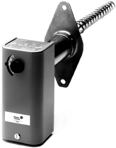
A28AK Thermostat
| Motor Ratings VAC | 120 | 208 | 240 | 277 |
| AC Full Load A | 6.0 | 3.4 | 3.0 | – |
| AC Locked Rotor A | 36.0 | 20.4 | 18.0 | – |
| Non-Inductive or Resistance Load A (Not Lamp Loads) | 10.0 | 9.2 | 8.0 | 7.2 |
| Pilot Duty | 125 VA, 24 to 277 VAC | |||
Note: When used as a two-circuit control, the total connected load must not exceed 2,000 VA.
| Multi-Stage Electromechanical Temperature Controls Code No. LIT-1927120 |
 A28 Two-Stage Industrial Thermostat (Watertight and Dusttight)
![]()
![]()
![]()
Description
The A28KA is a wide range temperature control with gasketed enclosure and two single-pole, double-throw (SPDT) switches.
Refer to the A19A, A19K, A28K Series Industrial Controls Remote Bulb Product Bulletin (LIT-125105) for important product application information
Features
- rugged steel enclosure
- liquid-filled sensing element that provides uniform control
Applications
This control is for refrigeration, air conditioning, and heating applications. This model incorporates a gasketed enclosure that can be used in a wide range of industrial and general purpose applications.
Repair Information
If the A28 Two-Stage Industrial Thermostat fails to operate within its specifications, replace the unit. For a replacement thermostat, contact the nearest Johnson Controls® representative.
Technical Specifications
Electrical Ratings
| Motor Ratings AC | 120 | 208 | 240 |
| AC Full Load A | 16.0 | 9.2 | 8.0 |
| AC Locked Rotor A | 96.0 | 55.2 | 48.0 |
| Non-Inductive or Resistance Load A (Not Lamp Loads) | 16.0 | 9.2 | 8.0 |
| Pilot Duty | 125 VA, 24 to 277 VAC | ||
Note: When used as a two-circuit control, the total connected load must not exceed 2,000 VA.
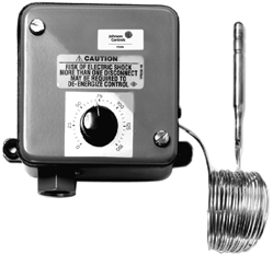
A28AKA Industrial Thermostat
Selection Chart
| Product Code | Switch
Action |
Range
°F (°C) |
Differential
F° (C°) |
Bulb and
Capillary |
Bulb Well No. | Range
Adjuster |
| A28KA-1C | Two-SPDT | 0 to 150
(-15 to 65) |
5 (2.8) each stage
3 (1.7) fixed between stages |
0.290 x 2-1/2 in.
10 ft capillary |
WEL16A-600R | Knob |
| Multi-Stage Electromechanical Temperature Controls Code No. LIT-1927125 |
![]() A28 Two-Stage Temperature Control with Weatherproof Enclosure
A28 Two-Stage Temperature Control with Weatherproof Enclosure
![]()
![]()
![]()
Description
The A28MA Controls are wide range temperature controls with rainproof NEMA 3R enclosure and two single-pole, double-throw (SPDT) switches.
Refer to the A28MA Type Two-Stage Tower Fan Control Two-Stage Air Cooled Condenser Fan Control Product Bulletin
(LIT-125135) for important product application information
Technical Specifications
Electrical Ratings
| Motor Ratings | 120 | 208 | 240 |
| AC Full Load A | 16.0 | 9.2 | 8.0 |
| AC Locked Rotor A | 96.0 | 55.2 | 48.0 |
| Non-Inductive or Resistance Load A (Not Lamp Loads) | 16.0 | 9.2 | 8.0 |
| Pilot Duty | 125 VA, 24 to 277 VAC | ||
Note: When used as a two-circuit control, the total connected load must not exceed
2,000 VA.
Features
- rugged steel enclosure
- liquid-filled sensing element provides uniform control
Applications
- sump water temperature control for cooling towers and evaporative condensers
- fan cycling control for air-cooled condensers
Repair Information
If the A28 Two-Stage Temperature Control with Weatherproof Enclosure fails to operate within its specifications, replace the unit. For a replacement control, contact the nearest Johnson Controls® representative.
Selection Chart
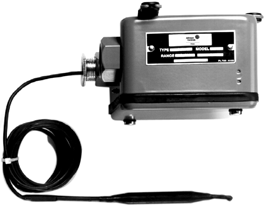
A28MA Temperature Control
| Multi-Stage Electromechanical Temperature Controls Code No. LIT-1927130 |
![]() A28 Two-Stage Agricultural Thermostat with NEMA 4X Enclosure
A28 Two-Stage Agricultural Thermostat with NEMA 4X Enclosure
![]()
![]()
![]()
Description
The A28PJ and A28PA are two-stage temperature controls with raintight and dusttight enclosures.
Refer to the A28 Series Two-Stage Temperature Controls with NEMA 1 Enclosure Product Bulletin (LIT-125130) for important product application information.
Features
- rugged thermoplastic gasketed enclosures that meet NEMA 4X specifications
- O-ring sealed setpoint adjustment knobs
- range scale with oversized white markings for easy readability in low light
- exposed portion of liquid-filled sensing elements are plated and plastic coated to resist damage in corrosive atmospheres
Selection Chart
| Product Code Number | Switch Action | Range °F (°C) | Differential F° (C°) | Bulb and Capillary | Range Adjuster |
| A28PJ-1C | Two-SPDT | 30 to 110
(-1 to 43) |
2 (1.1) each stage
2 to 7 (1.1 to 3.9) adjustable between stages |
1-3/8 in. x 2-1/4 in.
coiled |
Knob |
| A28PA-2C | Two-SPDT | 30 to 110
(-1 to 43) |
2 (1.1) each stage
2 to 7 (1.1 to 3.9) adjustable between stages |
1-3/8 in. x 2-1/4 in. coiled | Knob |
Electrical Ratings
Applications
Designed for use in agricultural and industrial applications that require compliance with Article 547 of the National Electrical Code.
Repair Information
If the A28 Two-Stage Agricultural Thermostat with NEMA 4X Enclosure fails to operate within its specifications, replace the unit. For a replacement thermostat, contact the nearest Johnson Controls® representative.
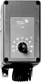
A28PJ, A28PA Thermostat
| Motor Ratings VAC | 120 | 208 | 240 | 277 |
| A28PJ | ||||
| AC Full Load A | 6.0 | 3.4 | 3.0 | – |
| AC Locked Rotor A | 36.0 | 20.4 | 18.0 | – |
| Non-Inductive or Resistance Load A (Not Lamp Loads) | 10.0 | 9.2 | 8.0 | 7.2 |
| Pilot Duty | 125 VA, 24 to 277 VAC1 | |||
| A28PA | ||||
| AC Full Load A | 16.0 | 9.2 | 8.0 | – |
| AC Locked Rotor A | 96.0 | 55.2 | 48.0 | – |
| Non-Inductive or Resistance Load A (Not Lamp Loads) | 16.0 | 9.2 | 8.0 | 7.2 |
| Pilot Duty | 125 VA, 24 to 277 VAC1 | |||
1. When used as a two-circuit control, the total connected load must not exceed 2,000 VA.
Multi-Stage Electromechanical Temperature Controls Code No. LIT-1927135
A36 Series Four-Stage Remote Bulb Thermostats
![]()
![]()
![]()
Sw itch
D ifferentia l
![]()
Description
The A36 series are four-stage thermostats with open construction for use in panel mounting.
Refer to the Type A36AHA 4-Stage Computer Environmental Temperature Control Product Bulletin (LIT-125145) for important product application information.
![]()
![]()
![]()
![]()
![]()
![]()
![]()
![]()
![]()
![]()
![]()
![]()
![]()
![]()
![]()
In ter sta ge Dif ferent ial
A36 Series Differential Diagram
Sw itch
D iffe ren tia l
Sw itch
D iffere n tial
a36diff.eps
Features
Screwdriver slot adjustment with calibrated dial enables movement of entire staging band within the range.
Applications
Use for cycling control for multiple refrigeration compressors or unloading type compressors.
Accessories
Order Enclosure CSE57A-600 separately, if required.
a36 IN.eps
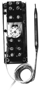
A36AHA-52 Remote Bulb Thermostat
Repair Information
If the A36 Series Four-Stage Remote Bulb Thermostat fails to operate within its specifications, replace the unit. For a replacement thermostat, contact the nearest Johnson Controls® representative.
A36 Series Action Diagram
![]()
![]()
![]()
![]()
![]()
![]()
![]()
![]()
![]()

Selection Chart
| Product Code | Switch
Action |
Range °F (°C) | Differential F° (C°)
Fixed |
Bulb and
Capillary |
Bulb Well No. | Range
Adjuster |
| A36AHA-50C1 | Four Single-Pole,
switches |
55 to 95
(13 to 35) |
Two each stage
1 1/2 (0.8) between stages |
3/8 in. x 5-1/4 in.
18 in. capillary w ith 12 in. nylon armor |
WEL14A-603R | Screwdriver slot with
calibrated dial |
| A36AHA-52C1 | ||||||
| A36AHA-58C2 | 0 to 70 | Three each stage
2-1/2 (1.4) between stages |
3/8 in. x 4-3/4 in.
15 ft braid armor capillary |
WEL14A-602R | ||
| A36AHB-33C1 | Two each stage
2-1/2 (1.4) between stages |
- Calibrated at mid-switching point; computer room or comfort control.
- Calibrated at low-switching point; special close control chiller applications.
Specifications
Maximum bulb temperature is 120°F (49°C) in operation and 140°F (60°C) when shipping.
Electrical Ratings (Per Switch)
| Motor Ratings VAC | 120 | 208 | 240 | 277 |
| A36AHA | ||||
| AC Full Load A | 10.0 | 6.9 | 5.0 | – |
| AC Locked Rotor A | 60.0 | 41.4 | 30.0 | – |
| Non-Inductive A | 16.0 | 9.2 | 8.0 | 7.2 |
| Pilot Duty | 125 VA, 120 to 227 VAC | |||
| A36AHB | ||||
| AC Full Load A | 6.0 | 3.4 | 3.0 | – |
| AC Locked Rotor A | 36.0 | 20.4 | 18.0 | – |
| Non-Inductive A | 10.0 | 5.7 | 5.0 | 4.3 |
| Pilot Duty | 125 VA, 120 to 227 VAC | |||
Multi-Stage Electromechanical Temperature Controls Code No. LIT-1922250
 S26 Series Switching Subbase
![]()
![]()
![]()
Description
The S26 Series is a switching subbase used in conjunction with T26A, T26J, and T26S thermostats to provide system and fan switching capability.
The variety of switching configurations available with the S26 Series adds application flexibility to the T26 Series thermostats.
Applications
S26 Series subbases are available with a variety of system switch configurations for manual control of system operation and fan speed for heating, cooling, and combination heating/cooling equipment.
Selection Chart
| Product Code
Number |
System
Switch |
Fan Switch |
| S26AA-1 | Heat-off-cool | Low-med-high |
| S26AH-1 | Heat-off-cool | None |
| S26DH-1 | Off-auto | None |
Refer to the S26 Series Switching Subbase Product Bulletin (LIT-125610) for important product application information.
Features
- mounts directly to a two-gang electrical box
- wiring connections enclosed and isolated from the user
- smooth action multi-position slide switches for dependable service
- can be added to existing T26 Series thermostats (new style with plastic cover)
- high-impact plastic enclosure
Repair Information
If the S26 Series Switching Subbase fails to operate within its specifications, replace the unit. For a replacement subbase, contact the nearest Johnson Controls® representative.
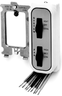
S26 Series Switching Subbase
Gray
Typical Wiring Configuration for Cooling S26
![]()
![]()
T26S and S26AH (T46SAH) Heat-Off-Cool Selector Switch with Continuous Fan (Heating and Cooling)

![]()
![]()
![]()
![]()
![]()
![]()
![]()
![]()
![]()
![]()
![]()
![]()
![]()
![]()
![]()
![]()
![]()
![]()
![]()
![]()
![]()
![]()
Black
FIG:T46SAH
| S26 Series System Switching Subbase | ||
| Finish | Cover | Almond |
| Faceplate | Gold metallic with dark brown border and lettering | |
| Material | Base | 0.050 in. (1 mm) cold rolled steel |
| Cover | 0.090 in. (2 mm) high impact PVC plastic | |
| Mounting | Mounts to a 2-gang electrical box | |
| Shipping Weight | Individual Pack | 7 oz (0.20 kg) |
| Overpack of 20 Units | 10 lb, 4 oz (4.65 kg) | |
| Wiring Connections | Color coded No. 16 AWG wires, 8 in. (203 mm) long | |
![]() Typical Wiring Configurations for Combinations
Typical Wiring Configurations for Combinations
| Electrical Ratings | ||||
| Motor Ratings | 120V | 208V | 240V | 277V |
| AC full load A | 12.0 | 6.9 | 6.0 | 5.2 |
| AC locked rotor A | 72 | 41.4 | 36 | 31.2 |
| AC non-inductive A | 6.5 | 6.5 | 6.5 | – |
| Pilot Duty | 125 VA, 24 to 277 VAC | |||
![]()
![]()
![]()

![]()
![]()
![]()
![]()
![]()
![]()
![]()
![]()
![]()
![]()
![]()
![]()
![]()
![]()
Black
Red
H C H C
Gray
![]()
T26S and S26AA (T46SAA) Heat-Off-Cool Selector Switch with Fan Speed Control (Heating and Cooling)
![]()
![]()
![]()
![]()
![]()
![]()

![]()
![]()
![]()
![]()
![]()
![]()
![]()
![]()
![]()
![]()
![]()
![]()
![]()
![]()
![]()
![]()
![]()
![]()
![]()
![]()
![]()
![]()
![]()
![]()
![]()
![]()
![]()
![]()
![]()
![]()
![]()
![]()
![]()
Black
T26S and S26DH (T46SDH) Off-Auto Selector Switch with Manual or Automatic Changeover Switch and
Gray
FIG:T46SAA
FIG:T4SDH
Continuous Fan (Heating and Cooling)
Multi-Stage Electromechanical Temperature Controls Code No. LIT-1922255
 T22/T25/T26 Series Line Voltage Wall Thermostat (Heating, Cooling, or Heating and Cooling)
![]()
![]()
![]()
Description
For line voltage control of residential, commercial, or industrial heating or year-round air conditioning. Heat or cold anticipators are not required. The
liquid-charged temperature sensing element and highly efficient diaphragm and leverage provide close temperature control.
Refer to the following documents for important product application information:
- T22 Series Line Voltage Thermostats with Selector Switch Product Bulletin
(LIT-125630)
- T25 Two-Stage Room Thermostat Product Bulletin (LIT-125640)
- T26 Series Line Voltage Thermostats Product Bulletin (LIT-125645)
Features
- attractive beige colored, high-impact plastic enclosure (T26 Series)
- close differential without the need for anticipators
- bi-metal thermometer supplied as standard except where indicated
- equipped with adjustable dial stops (T26 Series)
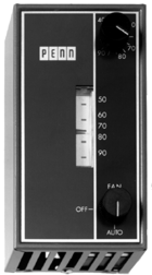
T22 Series Line Voltage Wall Thermostat
Series T25
![]()
![]()
![]()
![]()
![]()
![]()
![]()
Y
Y
B R
B
R
High Stage
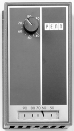
T25 Series Line Voltage Wall Thermostat
Low Stage
t28cd.eps
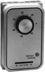
T25 Series Line Voltage Wall Thermostat
SeriesT26
![]()
![]()
![]()
![]()
3
2
1
t28cd.eps
Specifications
Action on Increase of Temperature
Action on Increase of Temperature
Temperature range is 40 to 90°F (5 to 30°C),
except energy conservation models.
Accessories
- replacement knobs and faceplates
- for double trim plate for mounting two T22s or T26s
Repair Information
If the T22/T25/T26 Series Line Voltage Wall Thermostat (Heating, Cooling, or Heating and Cooling) fails to operate within its specifications, replace the unit. For a replacement thermostat, contact the nearest Johnson Controls® representative.
Applications
Use for line voltage control of heating and cooling equipment.
T25, T26 Series Action Diagrams
| Multi-Stage Electromechanical Temperature Controls |
![]() T22/T25/T26 Series Line Voltage Wall Thermostat (Heating, Cooling, or Heating and Cooling) (Continued)
T22/T25/T26 Series Line Voltage Wall Thermostat (Heating, Cooling, or Heating and Cooling) (Continued)
![]()
![]()
![]()
Selection Chart
| Product Code
Number1 |
Type of
Adjustment |
Application | Selector
Switch |
Differential Approximately C° (F°) | Shipping
Wt. (lb) |
|
| Heating | Cooling | |||||
| Heating | ||||||
| T22AAA-1C | Knob | Single-Pole, Single-Throw (SPST) | Off-Auto | 1-3/4 (1) | – | 1.3 |
| T22ABC-1C | Auto-Off-Fan | |||||
| T22ABC-3C | Concealed | |||||
| T22BBC-1C | Knob | SPST, medium duty | 3 (1.7) | |||
| T22CBC-1C | SPST, heavy duty | |||||
| T22CBC-3C | Concealed | |||||
| T26A-14C | Knob | SPST, Energy Conservation Heating
model, max. setting 75°F (24°C) |
None | 2 (1.1) | 1.0 | |
| T26A-15C
(No Thermometer) |
SPST, Energy Conservation Heating
model, max. setting 65°F (18°C) |
|||||
| Cooling | ||||||
| T22JAA-1C | Knob | SPST | Off-Auto | – | 2-1/4 (1.3) | 1.3 |
| T22JCC-1C | Auto-Off-Fan | |||||
| T26J-7C | SPST, Energy Conservation Cooling
model, min. setting 75°F (24°C) |
None | ||||
| T26J-9C
(No Thermometer) |
SPST, Energy Conservation Cooling
model, min. setting 78°F (26°C) |
2 (1.1) | 1.0 | |||
| Heating and Cooling | ||||||
| T22SDA-1C | Knob | Single-Pole, Double-Throw (SPDT), | Off-Auto | 1-3/4 (1) | 2-1/4 (1.3) | 1.3 |
| T22SEB-1C | SPDT, used when the same device | Heat-Off-Cool | ||||
| T22SFB-1C2 | SPDT, used to control separate | |||||
| T22TFB-1C2 | SPDT, heavy duty, used to control | 3 (1.7) | 3 to 4 (1.7 to 2.2) | |||
| T26S-18C3 | SPDT | None | 1-3/4 (1) | 2-1/4 (1.3) | 1.0 | |
| T26T-3C2 | SPDT, heavy duty | 3 (1.7) | 3 to 4 (1.7 to 2.2) | |||
| Two-Stage | ||||||
| T25A-1C | Knob | Two SPDT switches
Two-stage heating, cooling or one- stage heating and one-stage cooling |
None | 1-3/4 (1) | 2-1/4 (1.3) | 1.5 |
| T25A-16C | Concealed | 3 (1.7) between stages | ||||
- For the thermostat guard, refer to G Series Thermostat and Humidistat Guards (LIT-1922145).
- Can also be used where one unit provides both heating and cooling by adding a jumper between terminals 2 and 3. Refer to Typical Wiring Diagram and Electrical Ratings for Line Voltage Thermostats (LIT-1922600).
- Includes a faceplate for horizontal mounting. The plate is for on-the-job installation over a vertical plate. Can field-convert to other configurations.
The T26S-18 is a universal replacement for Honeywell T451A, -B, T651A; White-Rodgers 179-1, 180-1, 181-1, 182-101, -102; Robertshaw® TA500, TH71,
-72, -79, -500, TX550.
T26T-3 replaces: Honeywell T4051A, -B, T6051A; White-Rodgers 151-6, 152-9, 159-3, -5.
Multi-Stage Electromechanical Temperature Controls Code No. LIT-1922600
 Typical Wiring Diagram and Electrical Ratings for Line Voltage Thermostats
![]()
![]()
![]()
Technical Specifications
H
![]()
![]()
![]()
![]()
![]()
![]()
![]()
![]()
![]()
![]()
![]()
![]()
Off
Off
h
H eat C ool H eat C ool
3
1
2
Cooling
System
Heating
System
G
t22sfb.eps
T22SFB, T22TFB
Typical Wiring Diagram for Line Voltage Thermostat
Electrical Ratings T22A, T22J, T22S, T25A, T26A, T26J, T26S
| Motor Ratings VAC | 120 | 208 | 240 | 277 |
| AC Full Load A | 6.0 | 3.4 | 3.0 | – |
| AC Locked Rotor A | 36.0 | 21 | 18.0 | – |
| AC Non-Inductive A | (1) | (1) | (1) | (1) |
| Pilot Duty | 125 VA, 24 to 277 VAC | |||
Note: T25A Non-Inductive Ratings are 10.0, 9.2, 8.0 and 7.2 A. T26A, T26S Non-Inductive Rating is 10.0 A,
120 to 277 VAC.
Electrical Ratings T22BBC
| Motor Ratings VAC | 120 | 208 | 240 |
| AC Full Load A | 10.0 | 6.9 | 6.0 |
| AC Locked Rotor A | 60.0 | 41.4 | 36.0 |
| Pilot Duty | 125 VA, 24 to 277 VAC | ||
Electrical Ratings T22CBC1, T26T2
| Motor Ratings VAC | 120 | 208 | 240 | |||
| Heat | Cool | Heat | Cool | Heat | Cool | |
| AC Full Load A | 16.0 | 8.0 | 9.2 | 8.0 | 8.0 | 8.0 |
| AC Locked Rotor A | 96.0 | 48.0 | 55.2 | 48.0 | 48.0 | 48.0 |
| Non-Inductive Rating | 120 | 240 | 227 | |||
| AC Non-Inductive A | 22.0 | 22.0 | 22.0 | |||
| Pilot Duty | 125 VA, 120 to 240 VAC | |||||
- Heating rating only applies. Non-inductive ratings do not apply to Type T2CBC.
- Non-inductive rating does not apply to the cooling side of T26T.
Electrical Ratings T22TFB
| Motor Ratings VAC | 120 | 208 | 240 | |||
| Heat | Cool | Heat | Cool | Heat | Cool | |
| AC Full Load A | 16.0 | 8.0 | 9.2 | 8.0 | 8.0 | 8.0 |
| AC Locked Rotor A | 96.0 | 48.0 | 55.2 | 48.0 | 48.0 | 48.0 |
| Pilot Duty | 125 VA, 120 to 240 VAC | |||||
Multi-Stage Electromechanical Temperature Controls Code No. LIT-1922260
 T23 Series Fan Coil Thermostat (with Fan and System Selectors)
![]()
![]()
![]()
Description
This line voltage thermostat controls heating, cooling, or combination heating and cooling systems. It operates fan motors, relays, or valves on fan-coil units. All thermostats have a three-speed fan selector switch.
Refer to the T23 Series Line Voltage Fan Coil Thermostat Product Bulletin (LIT-125635) for important product application information.
Features
- dual voltage switching provided (120/240 VAC) without the need for
anticipators to achieve close temperature control
- field-adjustable high and low dial stops
- mounts on a standard double outlet box
- attractive one-piece beige cover with inlaid two-tone panel
Applications
- line voltage control of fan motors, relays, or valves on fan-coil units
T23A Thermostat
2 3 Y h
MED
L O H I B
OF F
5 6 4
R
H E A T C O OL
![]()
![]()
![]()
![]()
![]()
![]()
![]()
![]()
![]()
![]()
![]()
![]()
![]()
2
3
Y
h
ME D
LO
HI
B
OF F
5
6
R
AU T O
t23a.eps
T23B Thermostat
![]()
![]()
![]()
![]()
![]()
2
3
Y
h
ME D
LO
HI
B
OF F
5
6
R
AU T O
![]()
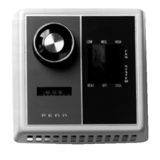
T23A-1 Thermostat
Repair Information
If the T23 Series Fan Coil Thermostat (with Fan and System Selectors) fails to operate within its specifications, replace the unit. For a replacement thermostat, contact the nearest Johnson Controls® representative.
t23b.eps
Selection Chart
Technical Specifications Mounts on a standard double outlet box. Electrical Ratings
| Motor Ratings VAC | 120 | 240 |
| AC Full Load Amperes | 5.8 | 2.9 |
| AC Locked Rotor Amperes | 34.8 | 17.4 |
| Pilot Duty | 125 VA, 120 to 240 VAC | |
Multi-Stage Electromechanical Temperature Controls Code No. LIT-1922265
 T28 Series Fan Coil Thermostat (with or without Fan Selector Switches)
![]()
![]()
![]()
Description
This thermostat controls light duty line voltage fan coil or baseboard valves on heating, cooling, and heating-cooling systems. The thermostat can control one or two valves directly. These thermostats are rated for 120, 208, or 240 VAC at 50 to 60 Hz.
Refer to the T28 Series Fan Coil Thermostats Product Bulletin (LIT-125650) for important product application information.
Features
- precision, snap-acting contacts
- heating and cooling anticipation
- cooling and heating-cooling models have an interlocked fan off position
Applications
Use for line voltage control of heating and cooling equipment.
![]()
![]()
HI ME D h
OFF
LO
T28CD
t28cd.eps
Heating-Cooling Thermostat with Off-Hi-Med-Lo Fan Switch
![]()
HI ME D h
OF F LO
T28DG
Sequenced Heating-Cooling Thermostat with Off-Hi-Med-Lo Fan Switch
t28dg.eps
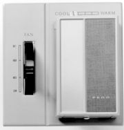
T28CD Thermostat
Repair Information
If the T28 Series Fan Coil Thermostat (with or without Fan Selector Switches) fails to operate within its specifications, replace the unit. For a replacement thermostat, contact the nearest Johnson Controls® representative.
Selection Chart
| Product Code Number | Fan Switch | Shipping Weight, lb (kg) |
| Cooling | ||
| T28BD-1C | Off-Hi-Med-Lo | 1.3 (0.59) |
| Heating-Cooling (Remote changeover, Single valve for heating and cooling)1 | ||
| T28CD-1C | Off-Hi-Med-Lo | 1.3 (0.59) |
| Heating-Cooling, Sequenced (Automatic changeover, Separate valves for heating and cooling)2 | ||
| T28DA-1C | None | 1.0 (0.45) |
| T28DB-1C1 | Off-On | 1.3 (0.59) |
| T28DD-1C1 | Off-Hi-Med-Lo | 1.3 (0.59) |
| T28DG-1C3 | Off-Hi-Med-Lo | 1.3 (0.59) |
- Off position of fan switch interlocks to turn off cooling.
- For automatic changeover where one valve functions for heating or cooling, use A19CAC-2 Strap-On Changeover Control.
- Off position of fan switch interlocks to turn off both heating and cooling.
Technical Specifications
The T28 mounts on a standard, double outlet box.
Nominal operating differential at 0.6°F (0.3 C°) heating, 1 F° (0.6 C°) cooling on standard 120 VAC fan coil valves. Sequenced models have 6 F° (3.3 C°) differential from heat on to cool on.
Electrical Ratings – Ampere
| VAC | Thermostat | Fan Switch | ||||
| Cooling | Heating | |||||
| Normal | Inrush | Normal | Inrush | Full Load Amperes | Locked Rotor Amperes | |
| 120 | 0.32 | 1.0 | 0.12 | 0.36 | 5.8 | 34.8 |
| 208 | 0.18 | 0.57 | 0.07 | 0.21 | 3.3 | 19.8 |
| 240 | 0.16 | 0.50 | 0.06 | 0.18 | 2.9 | 17.4 |
| Multi-Stage Electromechanical Temperature Controls Code No. LIT-1922270 |
![]() T46 Series Fan Coil Thermostat
T46 Series Fan Coil Thermostat
![]()
![]()
![]()
Description
The T46 Series Thermostat is used to control line voltage, fan coil, and heating zone valves on heating, cooling, and combination heating and cooling systems. Models are available with single-pole, single-throw (SPST) or single-pole, double-throw (SPDT) contact action for standard duty (nominal 1/4 hp,
6 A non-inductive) applications. Thermostats are available with or without fan speed control or built-in thermometers. Various system switch combinations are available, including fan speed selection.
Field-installable faceplate combinations of knob or concealed adjustment are possible. Also, the T46 is available with or without thermometer indication. These thermostats have plastic locking covers with an
Allen-head screw to discourage unauthorized tampering. Standard models are supplied with the thermostat faceplate installed with knob adjustment and thermometer.
Refer to the T46 Series Fan Coil Thermostats Product Bulletin (LIT-125655) for important product application information.
Selection Charts
T46 Series Fan Coil Thermostat
Features
- knob or concealed setpoint adjustment
- low and high temperature dial stops that are concealed and adjustable throughout setpoint range
- can be set for a locked dial
- narrow differential without the need for anticipator
- standard internal dual Celsius and Fahrenheit scales
- switch mechanism and wiring connections go into the switch box to isolate electrical circuits from the sensing element
- mounts on a standard double outlet box
- separable mounting plate allows easy mounting and wiring without removing thermostat cover
- locking cover reduces unauthorized tampering
- high-impact plastic enclosure
- smooth action multi-position slide switches for dependable service
Replacement Parts
| Product Code Number | Description |
| CVR88A-600R | Thermostat Cover Assembly for knob adjustment models with thermometer,
°F scale, faceplate supplied unassembled |
| KNB26A-600R | Plastic push on knob for thermostat |
| BKT48A-600R | Mounting plate for T46 |
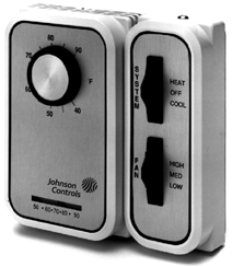
T46 Thermostat
Applications
These thermostats control fan coil and zone heating valves on a wide variety of heating and cooling combinations for conditioned space.
| Product Code
Number |
System
Switch |
Fan
Switch |
| Heating | ||
| T46ABH-1C | Auto-off-fan | None |
| T46ADH-1C | Off-auto | None |
| Cooling | ||
| T46JBH-1C | Auto-off-fan | None |
| T46JDH-1C | Off-auto | None |
| T46JEA-1C | On-off | Low-med-high |
| Heating and Cooling | ||
| T46SAA-1C | Heat-off-cool | Low-med-high |
| T46SAH-1C | Heat-off-cool | None |
| T46SDA-1C | Off-auto | Low-med-high |
| T46SDH-1C | Off-auto | None |
- Faceplates must be ordered in multiples of ten.
- Supplied with standard wholesaler models.
| T46 Series Fan Coil Thermostats | ||
| Range | Thermostat | 40 to 90°F (5 to 30°C) |
| Thermometer | 50 to 90°F (10 to 30°C) | |
| Differential | Mechanical | Approximately 0.7°F (0.4°C) |
| Operating | See next page | |
| Finish | Cover | Almond |
| Faceplate | Gold metallic with dark brown border and lettering | |
| Mounting | Double gang box, separable mounting plate | |
| Material | Base | 0.050 in. (1 mm) cold rolled steel |
| Cover | 0.090 in. (2 mm) high-impact plastic | |
| Sensing Element | Liquid-filled for positive trouble-free operation | |
| Shipping Weight | Individual Pack | 1 lb (0.45 kg) |
| Overpack of 20 Units | 20 lb (9.07 kg) | |
| Thermometer | Bimetal type for accuracy and clarity, can be field-calibrated | |
| Wiring Connections | Color coded No. 16 AWG wires, 8 in. (203 mm) long | |
Multi-Stage Electromechanical Temperature Controls
T46 Series Fan Coil Thermostat (Continued)
![]()
![]()
![]()
![]()
Technical Specifications (Continued)
Electrical Ratings
Typical Wiring Application for Heating
Black
![]()
![]()
![]()
![]()
![]()
![]()
![]()
![]()
![]()
![]()
![]()
| Motor Ratings | 120 V | 208 V | 240 V | 277 V |
| T46 System and Fan Switches | ||||
| AC Full Load A | 12.0 | 6.9 | 6.0 | 5.2 |
| AC Locked Rotor A | 34.8 | 19.1 | 17.4 | 14.4 |
| AC Non-Inductive A | 6.5 | 6.5 | 6.5 | – |
| Pilot Duty | 125 VA, 24 to 277 VAC | |||
| T46 Thermostat Only | ||||
| AC Full Load A | 6.0 | 3.5 | 3.0 | – |
| AC Locked Rotor A | 34.8 | 19.1 | 17.4 | – |
| AC Non-Inductive A | 6.5 | 6.5 | 6.5 | – |
| Pilot Duty | 125 VA, 24 to 277 VAC | |||
L1 (Hot)
Grey
Operating Differentials
5
T46A, T46S Heating
4
Operating Differential F 0
3
2.2
Orange
Red
Neutral
T46ABH Auto-Off-Fan Selector Switch with Continuous Fan (Heating Only)
Typical Wiring Application for Cooling
To Fan
To Heating
t46auht.eps
2
1
0
0 2 4 6 8
Amperage Load
1.1
L1 (Hot)
Operating Differential C 0
Bla ck
Grey
Orange
Blu e
To Fan
t46auco.eps
Operating Differential for T46A and Heating Side of T46S
t46heat.eps
Neutral
To Cool ing
T46JBH Auto-Off-Fan Selector Switch
![]()
![]()
![]()
![]()
![]()
![]()
![]()
![]()
![]()
![]()
![]()
5 with Continuous Fan (Cooling Only)
T46J, T46S Cooling
4 2.2
Operating Differential F 0
Operating Differential C 0
3
2 1.1
1
Typical Wiring Application for Combination
Fan
![]()
![]()
![]()
![]()
![]()
![]()
![]()
![]()
![]()
![]()
Orange
To
L1 (Hot)
Fan
Off
Changeover
Control
Blue
Y
B
Red
R
Valve
Neutral
Black
0
t46cool.eps
Grey
0 2 4 6 8
Amperage Load
Operating Differential for T46J and Cooling Side of T46S
Note: The heavy line in each of the above figures is the nominal operating temperature differential. Production thermostats may vary from the norm, as indicated by the dotted line.
T46SDH Off-Auto Selector Switch.
t46_2.eps
Used on Fan-Coil Unit with Cycling Valve and Continuous Fan.
Terminal Markings Shown for
A19CAC Changeover Control (Heating and Cooling)
| Multi-Stage Electronic Temperature Controls Code No. LIT-1900004 |
![]() MS Series Temperature Stage Control Modules
MS Series Temperature Stage Control Modules
![]()
![]()
![]()
Description
The MS Series Temperature Controls are versatile, microprocessor-based, multifunction, programmable temperature controls. They are designed for single and multiple-stage temperature control applications.
Depending on the model selected, the
MS Series Controls can operate in the following modes:
- Direct mode
- Reverse mode
- Deadband mode
- Independent Setpoint mode
The MS Series Controls have large, easy-to-read, red LED displays. These
compact controls are available in panel mount and DIN rail mount models. MS Series Controls use the A99B temperature sensors, which allow remote mounting of the display unit.
Refer to the MS Series Multi-Stage Electronic Temperature Controls Product Bulletin
(LIT-125198) for important product application information.
Features
- programmable functions allow adjustment of control settings to meet application needs
- alarm management functions provide visible alarm codes on the display
- easily readable LED display shows temperature and functions quickly and clearly
- programming button lockout allows user to disable programming buttons to deter accidental or unauthorized changes
- accurate temperature sensors provide precise control performance with up to 300 feet of wiring (An adjustable offset is provided for longer wiring)
- self-test procedure checks control operation by cycling all outputs and testing all LEDs

MS4 Series Panel and DIN Rail Mount, Multi-Stage, Electronic Temperature Controls
Repair Information
If the MS Series Temperature Stage Control Modules fails to operate within its specifications, replace the unit. For a replacement control, contact the nearest Johnson Controls® representative.
Applications
| Application | MS1 Series Single-Stage | MS2 Series Two-Stage | MS4 Series Four-Stage |
| Rooftop heating or cooling units | | | |
| Boiler or pump control | | | |
| Convenience store coolers | | | |
| Space temperature control | | | |
| Cooling tower pump control | | ||
| Compressor or chiller staging | | | |
| Reach-in coolers | | | |
| Supermarket display cases for produce | | | |
| Restaurant and Convenience store walk-in coolers | | |
Selection Chart
Accessories
ms4pm24t.eps
ms4dr24t.eps
Multi-Stage Electronic Temperature Controls
MS Series Temperature Stage Control Modules (Continued)
![]()
![]()
![]()
![]()
Technical Specifications
| MS Series Temperature Stage Control Modules | ||
| Power Requirements | 24 VAC, 50/60 Hz, Class 2 (20 to 30 VAC) | |
| Power Consumption | 5 VA at 24 VAC | |
| Accuracy | 1.8°F ( 1°C) | |
| Ambient Conditions | Operating | +14 to +140°F (-10 to +60°C); 0 to 95% RH (noncondensing) |
| Storage | -22 to +176°F (-30 to +80°C); 0 to 95% RH (noncondensing) | |
| Agency Listings | UL Recognized: File E194024, CCN XAPX2
Canadian UL Recognized: File E194024, CCN XAPX8 |
|
| Dimensions (H x W x D) | Panel Mount | 1.38 x 2.95 x 2.68 in. (35 x 75 x 68 mm) |
| DIN Rail | 4.65 x 2.76 x 2.07 in. (118 x 70 x 53 mm) | |
Electrical Ratings
| 120 VAC | 240 VAC | 24 VDC | |
| Horsepower | 1/4 | 1/2 | — |
| Full Load Amperes | 5.8 | 4.9 | — |
| Locked Rotor Amperes | 34.8 | 29.4 | — |
| Inductive (Non-Motor) Amperes | 8 | 8 | 8 |
| Pilot Duty VA | 275 | 450 | — |
Note: Relay outputs must not exceed 20 Amperes total connected load. Open collector transistors on the MS1 Alarm Circuits have a maximum rating of 40 VDC 100 mA. Alarms require separate power source.
![]()
![]()
![]()
![]()
![]()
![]()
![]()
![]()
![]()
![]()
![]()
Refer to Ratings Table for more information
Internal to Control
Stage Stage
1
3
Power
Stage
Stage Supply
2 4
Common
Binary Input
Auxiliary Temperature Sensor
Process Sensor
Binary/Sensor Common
C
1
2
3
4
| V1 | V2 | D | S2 | SC | S1 | ||
![]()

![]()
![]()
![]()
![]()
![]()
![]()
![]()
![]()
Terminal Not Used
Binary Input
Sensor Common
Process Sensor
Binary and Sensor Common
Auxiliary Temperature Stage Sensor
SC D CD S2 C2
Internal to Control
V1 V2
C1 1
C4
C3 3
Stage 1 Stage 4 Stage 3
Power Supply
See Ratings Table for more information
MS4PM24T Panel Mount Control Wiring MS4DR24T Din Rail Mount Control Wiring
| Multi-Stage Electronic Temperature Controls Code No. LIT-1900009 |
![]() MS Series Single-Stage Control Modules with Voltage Input
MS Series Single-Stage Control Modules with Voltage Input
![]()
![]()
![]()
Description
The MS Series Controls are versatile, microprocessor-based, multifunction, programmable controls for humidity, pressure, or other 0 to 10 VDC input. They are designed for single- and multiple-stage control applications.
Depending on the model selected, the MS Series Control can operate in one of several modes:
- Direct mode
- Reverse mode
- Deadband mode
- Independent Setpoint mode
The MS Series Controls have large, easy-to-read, red LED displays. These
compact controls are available in panel mount and DIN rail mount models.
Refer to the MS Series Multi-Stage Electronic Controls Product Bulletin (LIT-125502) for important product application information.
Applications
| Application | MS1 Series Single-Stage |
| Rooftop heating or cooling units | |
| Boiler or pump control | |
| Convenience store coolers | |
| Space temperature control | |
| Cooling tower pump control | |
Selection Chart
| Product Code Number | Description |
| MS1DR24T-11C | MS1 Single-Stage thermostat, DIN Rail Mount Control; A99 sensor included |
| MS1DR24V-11C | MS1 Single-Stage, DIN Rail Mount Control; 0 to10 VDC input; no sensor included |
| Product Code Number | Description |
| HE-6300-3
HE-6310-3 |
Humidity Sensor: 0 to 100% RH noncondensing
20 to 140°F (-29 to 60°C) |
Features
- programmable functions allow adjustment of control settings to meet application needs
- alarm management functions provide visible alarm codes on the display and alarm relay contacts that can be used to activate a remote alarm or dial-out modem
- easily readable LED display shows condition and functions quickly and clearly
- programming button lockout allows user to disable programming buttons to deter accidental or unauthorized changes
- provides accurate control performance with up to 300 feet of wiring (an adjustable offset is provided for longer wiring.)
- self-test procedure checks control operation by cycling all outputs and testing all LEDs
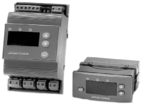
MS1 Series DIN Rail Mount, Single-Stage, Electronic Pressure, Temperator
Repair Information
If the MS Series Single-Stage Control Modules with Voltage Input fails to operate within its specifications, replace the unit. For a replacement control, contact the nearest Johnson Controls® representative.
| MS Series Stage Control Modules with Voltage Input | |
| Power Requirements | 24 VAC, 50/60 Hz, Class 2 (20 to 30 VAC) |
| Power Consumption | 5 VA at 24 VAC |
| Accuracy | 1.8°F ( 1°C) |
| Multi-Stage Electronic Temperature Controls |
![]()
Electrical Ratings
| MS Series Stage Control Modules with Voltage Input | ||
| Ambient Conditions | Operating | +14 to +140°F (-10 to +60°C); 0 to 95% RH (noncondensing) |
| Storage | -22 to +176°F (-30 to +80°C); 0 to 95% RH (noncondensing) | |
| Agency Listings | UL Recognized: File E194024, CCN XAPX2
Canadian UL Recognized: File E194024, CCN XAPX8 |
|
| Dimensions (H x W x D) | Panel Mount | 1.38 x 2.95 x 2.68 in. (35 x 75 x 68 mm) |
| DIN Rail | 4.65 x 2.76 x 2.07 in. (118 x 70 x 53 mm) | |
MS Series Single-Stage Control Modules with Voltage Input (Continued)
| 120 VAC | 240 VAC | 24 VDC | |
| Horsepower | 1/4 | 1/2 | — |
| Full Load Amperes | 5.8 | 4.9 | — |
| Locked Rotor Amperes | 34.8 | 29.4 | — |
| Inductive (Non-Motor) Amperes | 8 | 8 | 8 |
| Pilot Duty VA | 275 | 450 | — |
Note: Relay outputs must not exceed 20 Amperes total connected load. Open collector transistors on the MS1 Alarm Circuits have a maximum rating of 40 VDC 100 mA. Alarms require separate power source.
![]()
![]()
![]()
| Multi-Stage Electronic Temperature Controls Code No. LIT-1927375 |
![]()
Description
MS4PMUHVT Multi-Stage Electronic Temperature Control with Relay Pack
-
- Surface Mounted Design (SMD)
![]()
![]()
![]()
The MS4PMUHVT Control is intended for multi-stage temperature control applications. This microprocessor based control offers innovative features and state-of-the-art technology to improve all your staged temperature control applications.
Refer to the MS4PMUHVT Multi-Stage Electronic Temperature Control with Relay Pack Product Bulletin (LIT-125195) for important product application information.
Features
- four enclosed, line voltage relays provide direct control of motor loads without additional relays
- 120/240 VAC power supply eliminates need for separate transformers
- one control provides single-sensor multi-stage control or dual-sensor reset
control, which reduces need for warehouse or truck to stock multiple controls for similar applications
- accepts A99 sensor signal, which is suitable for a wide range of applications
Selection Charts
technology assures high quality, reliable components in a compact package
- keypad lock deters accidental changes to parameter settings
- listed for use on refrigeration equipment in accordance with Canadian and U.S. National standards
Applications
This control is specifically designed for the control of four-stage applications in the following configurations:
- four cooling stages with common setpoint
- four heating stages with common setpoint
- four stages with deadband (two heating stages and two cooling stages with common setpoint)
- two independent sets of two dependent stages (two heating stages and two cooling stages with independent setpoints)
Repair Information
If the MS4PMUHVT Multi-Stage Electronic Temperature Control with Relay Pack fails to operate within its specifications, replace the unit. For a replacement control, contact the nearest Johnson Controls® representative.
Technical Specifications
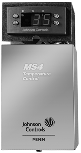
MS4PMUHVT Electronic Temperature Control
MS4PMUHV Multi-Stage Electronic Temperature Control with Relay Pack
| MS4PMUHVT Multi-Stage Electronic Temperature Control
with Relay Pack |
||
| Power Requirements | 120 VAC ±10% or 240 VAC ±10% | |
| Frequency | 60/50 Hz | |
| Power Consumption | 10 VA at 240 VAC, 10 VA at 120 VAC | |
| Sensor Range | -40 to 158°F (-40 to +70°C) | |
| Accuracy | ±1 F°/±1 C° | |
| Ambient Operating Conditions | MS4PMUHVT-11C | +14 to +140°F (-10 to +60°C);
0 to 95% RH (noncondensing) |
| MS4PM12CT-11C | +14 to +140°F (-10 to +60°C);
0 to 95% RH (noncondensing) |
|
| RP4MSUHV-1C | -40 to +140°F (-40 to +60°C);
0 to 95% RH (noncondensing) |
|
| Ambient Storage Conditions | MS4PMUHVT-11C | -22 to +176°F (-30 to +80°C);
0 to 95% RH (noncondensing) |
| MS4PM12CT-11C | -22 to +176°F (-30 to +80°C);
0 to 95% RH (noncondensing) |
|
| RP4MSUHV-1C | -40 to +185°F (-40 to +85°C);
0 to 95% RH (noncondensing) |
|
| Agency Listings | UL File SA516, Guide SDFY cUL File SA516, Guide SDFY7 | |
| Emissions Compliance | FCC (US), DOC (Canada) | |
| Dimensions (H x W x D) | 7.94 x 3-3/5 x 2-2/5 in. (202 x 92 x 61 mm) | |
| Shipping Weight | 2.9 lb (1,320 g) | |
| Product Code Number | Description |
| MS4PMUHVT-11C | Multi-Stage Electronic Temperature Control with
Relay Pack and One Temperature Sensor |
Accessories and Maintenance Parts
| Product Code Number | Description |
| A99BB-200C | Sensor with 6-1/2 ft/1.98 m Cable Length |
| MS4PM12CT-11C | Replacement Control (for use only with relay pack) |
| RP4MSUHV-1C | Replacement Relay Pack without Control |
Electrical Ratings per Relay
| 24 VAC | 120 VAC | 208 VAC | 240 VAC | |
| HP | — | 1/3 | 3/4 | 1 |
| FLA (Ampere) | — | 7.2 | 7.6 | 8 |
| LRA (Ampere) | — | 43.2 | 45.6 | 48 |
| Non-Inductive (Ampere) | — | 8 | 8 | 8 |
| Pilot Duty (VA) | 50 | 325 | 625 | 750 |
| Temperature Control Sensors and Accessories Code No. LIT-1900006 |
![]() A99B Series Temperature Sensor
A99B Series Temperature Sensor
![]()
![]()
![]()
Description
The A99B Series Temperature Sensors are passive PTC (Positive Temperature Coefficient) sensors. The A99B sensors are splashproof and are designed to measure temperature in a variety of refrigeration applications. Several accessories allow easy tailoring of the temperature sensor to various mounting configurations.
Applications include temperature sensing for freezers and coolers, as well as in defrost termination sensing, space and return air temperature sensing, and condenser fan cycling.
Refer to the A99B Series Temperature Sensors Product Bulletin (LIT-125186) for important product application information.
Selection Chart
| Product Code
Number |
Description |
| A99BA-200C | PTC Silicon Sensor with Shielded Cable;
Cable length 6-1/2 ft (2 m); Range: -40 to 212°F (-40 to 100°C) |
| A99BB-25C | PTC Silicon Sensor with PVC Cable; Cable length 9-3/4 in. (0.25 m); Range: -40 to 212°F (-40 to 100°C) |
| A99BB-200C | PTC Silicon Sensor with PVC Cable; Cable length 6-1/2 ft (2 m);
Range: -40 to 212°F (-40 to 100°C) |
| A99BB-300C | PTC Silicon Sensor with PVC Cable; Cable length 9-3/4 ft (3 m);
Range: -40 to 212°F (-40 to 100°C) |
| A99BB-500C | PTC Silicon Sensor with PVC Cable; Cable length 16-3/8 ft (5 m);
Range: -40 to 212°F (-40 to 100°C) |
| A99BB-600C | PTC Silicon Sensor with PVC Cable; Cable length 19-1/2 ft (6 m);
Range: -40 to 212°F (-40 to 100°C) |
| A99BC-25C | PTC Silicon Sensor with High Temperature Silicon Cable; Cable length 9-3/4 in. (0.25 m);
Range: -40 to 248°F (-40 to 120°C) |
| A99BC-300C | PTC Silicon Sensor with High Temperature Silicon Cable; Cable length 9-3/4 ft (3 m);
Range: -40 to 248°F (-40 to 120°C) |
| A99BC-500C | PTC Silicon Sensor with High Temperature Silicon Cable; Cable length 16-3/8 ft (5 m);
Range: -40 to 248°F (-40 to 120°C) |
| A99BC-1500C | PTC Silicon Sensor with High Temperature Silicon Cable; Cable length 49 ft (15 m);
Range: -40 to 248°F (-40 to 120°C) |
Features
- variety of lead lengths available to encompass most application requirements and simplify wiring sensors
- an assortment of mounting hardware provides configurations for many applications
- exceptional accuracy of sensing element provides excellent performance in a wide variety of control applications
- stainless steel sensing bulb allows use in more applications than other types of bulbs without corrosion
- lead length may be extended up to 800 ft (244 m)
Applications
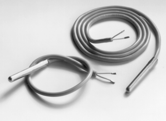
A99B Temperature Sensors
Repair Information
If the A99B Series Temperature Sensor fails to operate within its specifications, replace the unit. For a replacement sensor, contact the nearest Johnson Controls® representative.
The A99B temperature sensor line offers an economical solution for a wide variety of temperature sensing needs in refrigeration and HVAC applications.
Typical temperature sensing applications and environments include:
- freezers
- display cases
- walk-in coolers
- reach-in coolers
- defrost termination temperature sensing
- condenser fan cycling
- space and return air temperature sensing
- outdoor air sensing
- process cooling and heating
Technical Specifications
| A99B Series Temperature Sensor | ||
| Sensing Range | A99BA
A99BB |
-40 to 212°F (-40 to 100°C) |
| A99BC | -40 to 248°F (-40 to 120°C) | |
| Reference Resistance | 1,035 ohms at 77°F (25°C) | |
| Accuracy | 0.9°F (0.5°C)
between 5 and 167°F (-15 and 75°C) |
|
| Sensor Construction | Stainless steel probe | |
| Sensor Lead Wire Insulation | A99BA | Shielded PVC cable |
| A99BB | PVC cable | |
| A99BC | High temperature silicon cable | |
| Lead Wire Gauge | 22 AWG | |
| Maximum Allowable Bulb Temperature | 257°F (125°C) | |
| Ambient Operating Conditions | A99BA A99BB | -40 to 212°F (-40 to 100°C);
0 to 100% RH, condensing |
| A99BC | -40 to 248°F (-40 to 120°C);
0 to 100% RH, condensing |
|
| Ambient Storage Conditions | A99BA A99BB | 40 to 221°F (-40 to 105°C);
0 to 100% RH, condensing |
| A99BC | -40 to 266°F (-40 to 130°C);
0 to 100% RH, condensing |
|
Temperature Control Sensors and Accessories Code No. LIT-1922135
 Bulb Wells
![]()
![]()
![]()
Description
Bulb Wells are used in conjunction with Remote Bulb Temperature Controls where bulb insertion into a vessel or container to sense temperature is required. These wells are used with TE-6000 and TE-6300 Series Sensors.
A variety of shapes, sizes, and materials are available for a wide range of applications.
Refer to the appropriate temperature control for the exact bulb well required.
The Code No. FTG13A-600R Packing Nut Assembly is used in applications where the temperature does not fall below -35°F (-37°C). The maximum liquid pressure limit is 150 psig (1,034 kPa). Use with Style 1, 3/8 in. diameter bulb for direct immersion application. A19s require models with support tube; A70s and A72s do not need support tubes.
Selection Charts
WEL Series Bulb Wells
Repair Information
If the Bulb Wells fail to operate within thier specifications, replace the unit. For a replacement Bulb Well, contact the nearest Johnson Controls® representative.
WEL Series Bulb Well
![]()
![]()
![]()
![]()
![]()
![]()
WEL Series Bulb Wells
![]()
![]()
![]()
![]()
![]()
![]()
![]()
![]()
![]()
![]()
![]()
![]()
![]()
![]()
![]()
![]()

![]()
![]()
![]()
![]()
FIG:Wel_3
FIG:Wel_2
FTG13A-600R

![]()
![]()
![]()
![]()
![]()
![]()
![]()
Packing Nut
Interlocking Retainer Washers
½ in. N.P.T. Adaptor
Style 1
Bulb Support Tube
FIG:Wel_1
FIG:FTG13A_600R
| Product Code
Number |
See
Figure |
Dimension, in. | Pipe Thread, in. | Material | Maximum
Temp °F |
Maximum | Type of
Solder Joint |
Plating | ||||
| A | B | C | Inside
D |
Outside
E |
Connector | Tube | ||||||
| WEL11A-601R1 | 2 | 2-3/8 | 2-5/16 | .299 | – | 1/2 | Brass | Copper | 250 | 300 | Soft | – |
| WZ-1000-22 | 1 | 5-1/4 | 1-1/4 | .500 | 1/2 | 1/2 | Stainless steel | Stainless steel | 300 | 400 | – | – |
| WZ-1000-4 | 1 | 5-1/4 | 1-1/4 | .500 | 1/2 | 1/2 | Stainless steel | Stainless steel | 600 | 400 | – | – |
| WZ-1000-52 | 2 | 2-3/8 | 2-5/16 | .299 | – | 1/2 | Malleable | Brass | 250 | 300 | – | – |
| WEL14A-601R 3 | 3 | 7-9/16 | 1-13/16 | .430 | – | 1/2 | Brass | Copper | 250 | 300 | Silver | Brite-Dip |
| WEL14A-602R 3 | 3 | 4-15/16 | 1-13/16 | .430 | – | 1/2 | Brass | Copper | 250 | 300 | Silver | Brite-Dip |
| WEL14A-603R 3 | 3 | 5-13/16 | 1 13/16 | .430 | – | 1/2 | Brass | Copper | 250 | 300 | Silver | Brite-Dip |
| WEL16A-600R1 | 2 | 2-3/8 | 1-5/16 | .299 | – | 1/2 | Brass | Copper | 250 | 300 | Soft | – |
| WEL16A-601R | 2 | 2-13/16 | 1-13/16 | .375 | – | 1/2 | Brass | Copper | 250 | 300 | Soft | – |
| WEL17A-600R3 | 1 | 10-7/16 | 3/4 | .763 | 1/2 | 3/4 | Malleable | Copper | 250 | 250 | Silver | Tin |
| WEL17A-601R3 | 1 | 8-11/16 | 3/4 | .763 | 1/2 | 3/4 | Malleable | Copper | 250 | 250 | Silver | Tin |
| WEL17A-602R3 | 1 | 10-7/16 | 3/4 | .753 | 1/2 | 3/4 | Malleable | Steel | 250 | 540 | Silver | Tin |
| WEL17A-604R3 | 1 | 14-13/32 | 3/4 | .763 | 1/2 | 3/4 | Malleable | Copper | 250 | 250 | Silver | Tin |
| WEL18A-600R3 | 1 | 3-1/2 | 3/4 | .773 | 1/2 | 3/4 | Malleable | Steel | 250 | 150 | Silver | Tin |
| WEL18A-602R3 | 1 | 3-1/2 | 3/4 | .773 | 1/2 | 3/4 | Malleable | Brass | 250 | 150 | Silver | Tin |
- With phenolic bushing 0.093 in. slot
- Includes thermal compound
- For 11/16 in. diameter style 4 bulbs. Style 1 can be used, but is not fastened into well
T-800 Wells
| Product Code | Description |
| T-800-1605 | Brass well, 6-1/2 inch |
| T-800-1606 | Stainless steel well, 5-1/4 inch |
| T-800-1618 | Brass well, 9-1/2 inch |
| T-800-1620 | Brass well, 9-1/2 inch |
| Temperature Control Sensors and Accessories Code No. LIT-1922145 |
![]() G Series Thermostat and Humidistat Guards
G Series Thermostat and Humidistat Guards
![]()
![]()
![]()
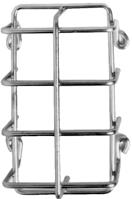
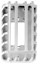
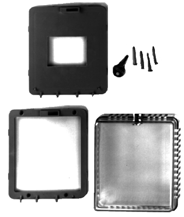
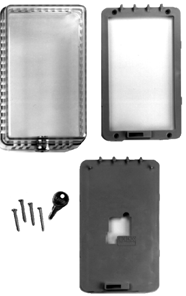
GRD10-1R
Wire Guard
GRD10A-601
Cast Aluminum Guard
GRD10A-608
Large Clear Plastic Guard
GRD10A-609
Rectangular Clear Plastic Guard
Description
The G Series Guards protect thermostats and humidistats from damage, vandalism, tampering, and unauthorized adjustment.
They are available in plastic, cast aluminum, or wire construction.
Features
• clear plastic guards have tumbler-type key locks
• GRD10A-608 and -609 include a mounting ring for mounting to a wall or flat surface
• plastic baseplate and plastic mounting ring available
• the baseplate mounts to a flat surface or to a single or double outlet box
• the mounting ring permits mounting over a thermostat or humidistat already installed
Applications
Ideal for locations where locked protection is required, such as schools, warehouses, churches, hospitals, or offices.
Selection Chart
Repair Parts
Replacement key KEY12A-600 (set of two) is available.
Temperature Control Sensors and Accessories
G Series Thermostat and Humidistat Guards (Continued)
![]()
![]()
![]()
![]()
![]()
![]()
![]()
![]()
![]()
![]()
![]()
![]()
![]()
![]()
![]()
![]()
![]()
![]()
![]()
![]()
![]()
![]()
![]()
6-3/4 (171)
![]()
![]()
(64)
2-2/3
(68)
![]()
![]()
![]()
![]()
![]()
![]()
![]()
![]()
3-3/8 (86)
6-1/5 (157)
6-3/4 (171)
1-2/5 (36)
3-5/8
(92)
4-1/5
(106)
![]()
(127)
2-7/8 (73)
1-5/8 (41)
4-3/4 (121)
grd10a_dm.eps
![]()
7-2/3 (195)
![]()
![]()
3-2/3 (94)
6-3/8 (162)
4-3/4 (121)
3-1/3 (84)
1-5/8 (41)
4-1/5
(106)
2-2/3
(68)
![]()
5-4/5 (148)
![]()
5-1/3 (135)
4-2/3 (119)
6-5/9
(167)
1-5/8
(41)
grd10a_dm2.eps
3-1/3
(84)
G Series Dimensions, in. (mm)
Temperature Control Sensors and Accessories Code No. LIT-1922285
T22, T25, T26, T28, T46, and T91 Accessories
![]()
![]()
![]()
![]()
Description
Replacement Knob and Cover Kits
Replacement Knob Kit numbers KNB17A-600R, KNB20A-600R, and
KNB26A-600R are designed as direct replacements for original equipment knobs.
Faceplates
Faceplates are available with metal or plastic covers.
Thermostat Trim Plates
Trim plate PLT231-1R is for mounting two wall thermostats such as T22, T25, T26, T58, T91 or one thermostat and one humidistat on a three-gang electrical box. The PLT61A-600 is a similar three-gang plate but with one cutout and a 3/8 in. hole for mounting accessory switches.
These plates are finished in tawny silver to complement the design of the thermostat and humidistat.
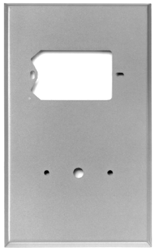
PLT61A-600 Faceplate
Selection Charts
Replacement Knob and Cover Kits
Faceplates
Trim Plates
| Product Code Number | Description | Replacement Trim Plate For |
| PLT231-1R | Tawny silver trim plate | T22, T25, T26, T28, T58, T91, W42, W43 |
Temperature Control Sensors and Accessories Code No. LIT-1922280
 T91 Series Room Temperature Sensor
![]()
![]()
![]()
Description
The T91 Series Temperature Sensor is a solid state thermistor sensor detects temperature changes in a room or similar space.
Series T91 Sensors may be used directly with Series M100Q Motor Actuators.
Refer to the T91 Thermistor Room Temperature Sensor Product Bulletin (LIT-125675) for important product application information.
Applications
Use for room or space temperature sensing to position sequencers or actuators for heating and/or cooling systems.
Selection Chart
Features
• highly sensitive thermistor sensing element
• fast response
• integral Fan and System switch options
• vertical or horizontal mounting
• three types of adjusters: external knob, concealed knob, or provisions for remote setpoint
• easy to install and wire
• separable mounting plate with screws saves installation time
Repair Information
If the T91 Series Room Temperature Sensor fails to operate within its specifications, replace the unit. For a replacement sensor, contact the nearest Johnson Controls® representative.
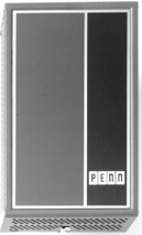
T91 Series Room Temperature Sensor
| Product Code | Range
°F (°C) |
Thermometer | Setpoint Adjustment | Switches | |
| Fan | System | ||||
| T91BAA-1C | 40/90 (5/32) | No | Remote | – | – |
| T91BBA-1C | 40/90 (5/32) | No | Concealed | – | – |
| T91BCA-1C | 40/90 (5/32) | Yes | Knob | – | – |
1. Supplied with vertical faceplate installed.
Technical Specifications
| T91 Series Room Temperature Sensor | |
| Ambient Temperature | -40 to 140°F (-40 to 60°C) |
| Baseplate | 0.050 in. (1 mm) cold rolled steel with dichromate dip finish |
| Cover | 0.025 in. (1 mm) cold rolled steel. Baked on tawny silver finish. Faceplate is aluminum with dark brown and light brown finish. Letters and markings are bright aluminum surface. |
| Electrical Rating for Switches | 5 A at 24 VAC |
| Wiring Connections | 6 in. No. 18 color coded wire leads |
Standard Electromechanical Pressure Controls Code No. LIT-1927175
 P10 Series Low Pressure Control
![]()
![]()
![]()
Description
The P10 Series Pressure Controls open or close electrical circuits from a change in operating air pressure. R to Y terminals make (cut-in) on pressure rise
Refer to the P10 Series Low Range Pressure Controls Product Bulletin (LIT-125400) for important product application information.
.
P10 Series
![]()
![]()
![]()
![]()
![]()
Y
R
B
B
Y
R
Action on Increase of Pressure
p10.eps
P10 Series Action Diagram
Selection Chart
Features
• visible calibrated adjustable range scale
• snap-acting switch in a dust protected enclosure
• easily accessible wiring terminals
Applications
• pneumatic systems
• control of pumps or small air compressors
Accessories
No. BKT16A-600 as well as a barbed fitting supplied as standard
• model P10FC-4 has a jumper installed on the common terminals
Repair Information
If the P10 Series Low Pressure Control fails to operate within its specifications, replace the unit. For a replacement control, contact the nearest Johnson Controls® representative.
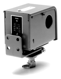
P10BC-7
with Bracket No. BKT16A-600R
Technical Specifications
• model P10BJ-1 is rated for 24 A non-inductive when used as a
single-pole, single-throw (SPST) (R-Y). (See Electrical Ratings chart below.)
Electrical Ratings (Part 1 of 2) |
Motor Ratings VAC | 120 | 208 | 240 | 277 | 600 | |||||||
| AC Locked Rotor A | 96.0 | 55.2 | 48.0 | 42 | – | ||||||||
| Non-Inductive
A |
Double Throw | 16.0 | 16.0 | 16.0 | 16.0 | 16.0 | |||||||
| Single Throw | 24.0 | 24.0 | 24.0 | 24.0 | 24.0 | ||||||||
| Pilot Duty | 125 VA, 24 to 600 VAC | ||||||||||||
| Motor Ratings VAC | 120 | 208 | 240 | 277 | 600 | P10FC-4 | |||||||
| P10BC-7 | AC Full Load A | 16.0 | 9.2 | 8.0 | 7.0 | – | |||||||
| AC Full Load A | 16.0 | 9.2 | 8.0 | 7.0 | – | AC Locked Rotor A | 96.0 | 55.2 | 48.0 | 42.0 | – | ||
| AC Locked Rotor A | 96.0 | 55.2 | 48.0 | 42.0 | – | Non-Inductive A | 16.0 | 9.2 | 8.0 | 7.2 | – | ||
| Non-Inductive A | 16.0 | 9.2 | 8.0 | 7.2 | – | Pilot Duty | 125 VA, 24 to 277 VAC
On two- and three-stage models, maximum connected load shall not exceed 2,000 VA |
||||||
| Pilot Duty | 125 VA, 24 to 277 VAC | ||||||||||||
| P10BG-3 | |||||||||||||
| P10PA-11 | |||||||||||||
| AC Full Load A | 6.0 | 3.4 | 3.0 | – | – | ||||||||
| AC Locked Rotor A | 36.0 | 20.4 | 18.0 | – | – | AC Full Load A | 6.0 | 3.4 | 3.0 | – | – | ||
| Non-Inductive A | 6.0 | 3.4 | 3.0 | 2.6 | – | AC Locked Rotor A | 36.0 | 20.4 | 18.0 | – | – | ||
| Pilot Duty | 125 VA, 24 to 277 VAC | Non-Inductive A | 6.0 | 3.4 | 3.0 | – | – | ||||||
| P10BJ-1 | Pilot Duty | 125 VA, 24 to 277 VAC
On two- and three- stage models, maximum connected load shall not exceed 2,000 VA |
|||||||||||
| AC Full Load A | 16.0 | 9.2 | 8.0 | 7 | – | ||||||||
Electrical Ratings (Part 2 of 2)
Standard Electromechanical Pressure Controls Code No. LIT-1927180
 P20 Series Air Conditioning/Pressure Cutout Control
![]()
![]()
![]()
Description
The P20 Series are field replacement high and low pressure controls for non-corrosive refrigerants. They include a dust-tight contact unit with quick connect connectors, and a
36 in. or 42 in. capillary with 1/4 in. sweat section. The setpoint is screwdriver adjustable.
Refer to the P20, P21 Series Air Conditioning Limit Controls Product Bulletin (LIT-125415) for important product application information.
Features
• accurate repeatability
• compact size
• trip-free manual reset
Applications
• air conditioning high/low pressure control
• refrigeration high/low pressure control
• head pressure control
Repair Information
If the P20 Series Air Conditioning/Pressure Cutout Control fails to operate within its specifications, replace the unit. For a replacement control, contact the nearest Johnson Controls® representative.
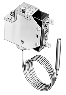
P20DB-1 Air Conditioning/ Pressure Cutout Control
SPST
Construction
SPDT
Construction
Red Red
![]()
![]()
![]()
![]()
![]()
![]()
![]()
![]()
![]()
![]()
![]()
![]()
Blue
(Open High)
Yellow (Open Low)
Yellow (Open Low)
Blue
(Open High)
Seal
White: Open Low Control Red: Open High Control
Low Range High Ranges
Control action is identified by
p20spst.eps
colored sealing compound or terminal markings on switch.
Selection Chart
1. Mounting bracket supplied on all models.
2. Replaces Ranco® G20-4412; Robertshaw® 3126-216, 3160-212
3. Replaces Ranco G23-5253; Robertshaw 3127-220, 3161-205; Honeywell® P430X-1250, 1268, 1292, 1300
4. Replaces Ranco G20-4050; Robertshaw 3126-116, 3160-012, 3160-014; Honeywell P431X-1092, 1100
5. Replaces Ranco G23-5052; Robertshaw 3127-140, 3127-414, 3161-009; Honeywell P430X, 1235, 1243, 1276, 1284
Standard Electromechanical Pressure Controls
![]()
Accessories
![]()
![]()
![]()
P20 Series Air Conditioning/Pressure Cutout Control
| Product Code Number | Description |
| 210-604R | Black phenolic resin spring clip snap-on insulated terminal cover |
Technical Specifications
Electrical Ratings
| Motor Ratings VAC | 120 | 208 | 240 | 277 |
| AC Full Load A | 16.0 | 9.2 | 8.0 | 7.0 |
| AC Locked Rotor A | 96.0 | 55.2 | 48.0 | 42.0 |
| SPDT | 16.0 | 16.0 | 16.0 | – |
| Pilot Duty | 125 VA at 24 VAC, 720 VA at 120 to 277 VAC | |||
Standard Electromechanical Pressure Controls Code No. LIT-1927190
 P29 Series Low Pressure Control with Time Delay
![]()
![]()
![]()
Description
P29NC is a low pressure control with time delay and lockout, which requires manual reset. A drop in pressure energizes the time delay relay and opens a contact after the time delay, shutting down the equipment. The time delay prevents nuisance shutdowns due to momentary fluctuations in system pressures.
Refer to the P29 Series Low Pressure Cutout Control with Time Delay Relay Product Bulletin (LIT-125425) for important product application information.
Features
• direct reading scale indication
• dust-protected snap action switch
• trip-free manual reset
• replacement timing relays available
Selection Chart
Applications
• chiller low temperature
• industrial equipment, oil pressure lubrication
• low suction pressure
Technical Specifications
• pilot duty rating of 750 VA, 120/240 VAC
• external step down transformer for 440 and 550 VAC applications must be of sufficient capacity to supply 15 VA at 120 VAC or 30 VA at 240 VAC for time delay
Accessories
• universal mounting bracket (271-51)
• replacement timing relays (Refer to Replacement Timing Relays for P28 and P29 Lube Oil Controls Catalog Page [LIT-1927395].)

P29 Series Low Pressure Control
Repair Information
If the P29 Series Low Pressure Control with Time Delay fails to operate within its specifications, replace the unit. For a replacement control, contact the nearest Johnson Controls® representative.
1. With alarm contacts
Example: Setpoint at 10 psig. On a rise in pressure, the timing circuit opens at 10 psig and time out ends. On a fall in pressure, the timing circuit energizes at 6 to 9 psig and the time out begins. If the pressure fails to reach 10 psig within the 60 second time delay, the main contacts open, shutting down the controlled equipment.
Standard Electromechanical Pressure Controls Code No. LIT-1927205
 P47 Series Steam Pressure Limit Control
![]()
![]()
![]()
Description
The P47 Controls are available with single-pole, single-throw (SPST), double-pole, single-throw (DPST), or
four-wire, two-circuit contacts for line voltage or low voltage. The pressure connector is 1/4 in. external NPT (0 to 15 psi only) or
1/4 in. internal NPT (for all other ranges).
Refer to the P47 Series Steam Pressure Controls Product Bulletin (LIT-125450) for important product application information.
Features
• long-life contact structure with high contact force
• easy-to-adjust single sight set scales show both cut-in and cut-out settings
Selection Chart
| Product
Code Number |
Switch Action | Range
psi (kPa) |
Diff psi (kPa) | Max.
Over-pressure psig (kPa) |
|
| Min. | Max. | ||||
| Contacts Open On Rise – Automatic Reset | |||||
| P47AA-1C | SPST | 0 to 15 (0 to 103) | 2 (14) | 8 (55) | 50 (345) |
| P47AA-4C | 20 in. Hg to 50 (-68 to 345) | 5 (34) | 35 (241) | 180 (1,241) | |
| P47AA-13C | 0 to 150 (0 to 1,034) | 12 (83) | 50 (345) | 325 (2,241) | |
| Contacts Close On Rise – Automatic Reset | |||||
| P47BA-1C | SPST | 0 to 15 (0 to 103) | 2 (14) | 8 (55) | 50 (345) |
| P47BA-6C | 0 to 150 (0 to 1,034) | 12 (83) | 50 (345) | 325 (2,241) | |
| Four-Wire, Two Circuit1 – Automatic Reset | |||||
| P47GA-9C1 | Main open high;
Auxiliary open low |
0 to 150 (0 to 1,034) | 12 (83) | 50 (345) | 325 (2,241) |
| P47AB-3C | SPST | 50 to 240 (345 to 1,655) | Manual reset | 300 (2,069) | |
| P47EA-1C | SPDT | 50 to 240 (345 to 1,655) | 10 (69) Fixed | 300 (2,069) | |
Applications
P47 steam pressure controls are designed for high limit or operating control applications. A typical use is as a limit control on steam heating systems. Models that close on a pressure increase are used on steam unit heaters to avoid blower operation when steam pressure is below the point required for adequate heating. The P47 can be used with steam, water, air, or noncombustible gases that do not harm iron or copper.
The Part No. TBG16A-600 Siphon is supplied with all controls except models with
0 to 15 psi range.
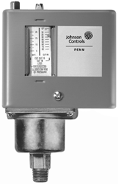
P47AA-1 Steam Pressure Limit Control
Repair Information
If the P47 Series Steam Pressure Limit Control fails to operate within its specifications, replace the unit. For a replacement control, contact the nearest Johnson Controls® representative.
1. The main contacts (Line-M2) open on rise, as the auxiliary contacts (Line-M1) close.
![]()
![]()
![]()
![]()
P47AA
Opens on Pressure Rise
P47BA
Closes on Pressure Rise
Technical Specifications
Electrical Ratings for P47AA, P47AB, and P47BA
| Motor Ratings VAC | 120 | 208 | 240 | 277 |
| AC Full Load A | 16.0 | 9.2 | 8.0 | – |
| AC Locked Rotor A | 96.0 | 55.2 | 48.0 | – |
| AC Non-Inductive A | 16.0 | 16.0 | 16.0 | 16.0 |
| Pilot Duty | 125 VA, 120 to 600 VAC; 57.5 VA, 120 to 300 VDC | |||
Electrical Ratings for P47EA
p47ga_1.eps
| Motor Ratings VAC | 120 | 208 | 240 | 277 |
| AC Full Load A | 16.0 | 9.2 | 8.0 | – |
| AC Locked Rotor A | 96.0 | 55.2 | 48.0 | – |
| AC Non-Inductive A | 16.0 | 10.0 | 10.0 | 10.0 |
| Pilot Duty | 125 VA, 120 to 227 VAC | |||
Electrical Ratings for P47GA
p47ga_2.eps
| Pole Number | Line-M2 (Main) | Line-M1 (Auxiliary) | ||||||
| Motor Ratings VAC | 120 | 208 | 240 | 277 | 120 | 208 | 240 | 277 |
| AC Full Load A | 16.0 | 9.2 | 8.0 | – | 6.0 | 3.3 | 3.0 | – |
| AC Locked Rotor A | 96.0 | 55.2 | 48.0 | – | 36.0 | 19.8 | 18.0 | – |
| AC Non-Inductive A | 16.0 | 9.2 | 8.0 | 7.2 | 6.0 | 6.0 | 6.0 | 6.0 |
| Pilot Duty: Both Poles | 125 VA, 120 to 600 VAC; 57.5 VA, 120 to 300 VDC | |||||||
SPST
![]()
![]()
![]()
![]()
P4 7 G A
Four-Wire, Two-Circuit Action on Pressure Rise
Standard Electromechanical Pressure Controls Code No. LIT-1927215
 P67 Series Low Pressure Control
![]()
![]()
![]()
Description
P67 pressure controls are used to close or open an electrical circuit, based on a predetermined air pressure signal. The operating point of the control and the differential, are easy to adjust with the externally located adjustment screws on the top of the control enclosure. The pressure controls incorporate a non-metallic diaphragm that is positioned by air pressure changes. The diaphragm, in turn, actuates a heavy-duty electrical contact block using a lever mechanism.
Refer to the P67 Series Low Range Pressure Control Product Bulletin (LIT-121445) for important product application information.
Selection Chart
Features
• long-life contact structure, high contact force
• easy-to-adjust settings: single sight-set scales show both cut-in and cut-out settings
Applications
Typical applications include the control of air compressors, fans, pilot lights, resistance heating elements, and other devices.
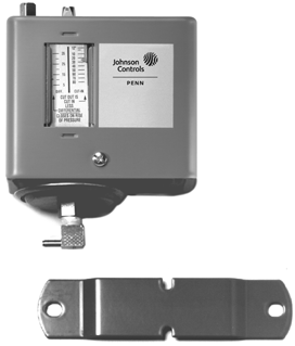
P67 Series Low Pressure Control with 271-350 Mounting Bracket
| Product
Code Number |
Control
Action |
Scale
Range psi1 (kPa) |
Temp.
Range |
Diff.
psi (kPa) |
Maximum
Over- pressure psig (kPa) |
Connector |
| P67AA-1C | Double-Pole, Single-Throw
(DPST) opens on pressure drop |
3 to 30
(21 to 207) |
32 to
140°F 0 to 60°C |
1-1/2-20
(10 to 138) Adjustable |
50 (345) | Angle
Barbed Fitting |
| P67CA-1C | DPST opens on pressure rise | |||||
| P67EA-5C | L-M2 contacts connect on
pressure rise and simultaneously the L-M1 contacts break |
1/8 in.
External NPT |
If the P67 Series Low Pressure Control fails to operate within its specifications, replace the unit. For a replacement control, contact the nearest Johnson Controls® representative.
1. Range is minimum cut-out to maximum cut-in on Open Low controls. It is minimum cut-in to maximum cut-out on Open High controls.
Technical Specifications
Electrical Ratings for P67AA and P67CA
![]()
![]()
![]()
![]()
![]()
![]()
Electrical Ratings for P67EA and P67FA
| Pole Number | LINE-M2 (Main) | LINE-M1 (Auxiliary) | ||||||
| Motor Rating VAC | 120 | 208 | 240 | 277 | 120 | 208 | 240 | 277 |
| AC Full Load A | 16.0 | 9.2 | 8.0 | – | 6.0 | 3.3 | 3.0 | – |
| AC Locked Rotor A | 96.0 | 55.2 | 48.0 | – | 36.0 | 19.8 | 18.0 | – |
| AC Non-Inductive A | 16.0 | 9.2 | 8.0 | 7.2 | 6.0 | 6.0 | 6.0 | 6.0 |
| Pilot Duty | 125 VA, 120 to 600 VAC; 57.5 VA, 120 to 300 VDC | |||||||
| Motor Ratings VAC | 1 Phase | 2 – 3 Phase | ||||
| 120 | 208 | 240 | 277 | 208 | 240 | |
| AC Full Load A | 12.0 | 12.0 | 12.0 | – | 12.0 | 12.0 |
| AC Locked Rotor A | 72.0 | 72.0 | 72.0 | – | 72.0 | 72.0 |
| AC Non-Inductive A | 12.0 | 12.0 | 12.0 | 12.0 | – | – |
| DC Non-Inductive A | 3.0 | 0.5 | 0.5 | – | – | – |
| Pilot Duty | 125 VA, 120 to 600 VAC; 57.5 VA, 120 to 300 VDC | |||||
P67 Wiring Diagram (no alarm) P67 Dimensions, in. (mm)
![]()
![]()
![]()
![]()
![]()
Line
Line
M2
Line
M1
Line
Load
Action on
Pressure Increase
![]()
![]()
![]()
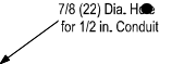
![]()
![]()
![]()
![]()
![]()
![]()
![]()
![]()
Standard Electromechanical Pressure Controls Code No. LIT-1927220
 P70, P72 Approximate Low Pressure Settings for Typical Applications
![]()
![]()
![]()
| Vacuum – in. Hg | Approximate Temperature
°F |
Pressure – psig1 | ||||||||||
| Application | Refrigerant | |||||||||||
| R-12 | R-22 | R-502 | R-717 | R-134A | ||||||||
| Cut-Out | Cut-In | Cut-Out | Cut-In | Cut-Out | Cut-In | Cut-Out | Cut-In | Cut-Out | Cut-In | Cut-Out | Cut-In | |
| Ice Cube Maker – Dry Type Coil | -11 | 14 | 4 | 17 | 16 | 37 | 22 | 45 | – | – | 2 | 15 |
| Sweet Water Bath – Soda Fountain | 20 | 31 | 21 | 29 | 43 | 56 | 52 | 66 | 33 | 45 | 18 | 26 |
| Beer, Water, Milk Cooler, Wet Type | 17 | 31 | 19 | 29 | 40 | 56 | 48 | 66 | – | – | 16 | 26 |
| Ice Cream Trucks, Hardening Rooms | -16 | 10 | 2 | 15 | 13 | 34 | 18 | 41 | 5 | 24 | 0 | 13 |
| Eutectic Plates, Ice Cream Truck | -21 | -11 | 1 | 4 | 11 | 16 | 16 | 22 | 4 | 8 | 1 | 2 |
| Walk In, Defrost Cycle | 9 | 37 | 14 | 34 | 32 | 64 | 40 | 75 | 23 | 55 | 12 | 32 |
| Reach In, Defrost Cycle | 20 | 39 | 19 | 36 | 40 | 68 | 48 | 78 | 30 | 57 | 16 | 36 |
| Vegetable Display, Defrost Cycle | 7 | 38 | 13 | 35 | 30 | 66 | 38 | 77 | – | – | 10 | 34 |
| Vegetable Display Case – Open Type | 12 | 45 | 16 | 42 | 35 | 77 | 44 | 89 | – | – | 14 | 40 |
| Beverage Cooler, Blower Dry Type | 11 | 37 | 15 | 34 | 34 | 64 | 42 | 75 | 24 | 55 | 12 | 32 |
| Retail Florist – Blower Coil | 29 | 45 | 28 | 42 | 55 | 77 | 65 | 89 | 44 | 67 | 26 | 40 |
| Meat Display Case – Defrost Cycle | 19 | 38 | 17 | 35 | 37 | 66 | 45 | 77 | – | – | 15 | 34 |
| Meat Display Case – Open Type | 4 | 28 | 11 | 27 | 27 | 53 | 35 | 63 | – | – | 8 | 25 |
| Dairy Case – Open Type | 2 | 38 | 10 | 35 | 26 | 66 | 33 | 77 | – | – | 16 | 34 |
| Frozen Food – Open Type | -32 | -9 | 7 | 5 | 4 | 17 | 8 | 24 | – | – | 10 | 3 |
1. Conversion factor: 1 psig = 6.9 kPa
Note: These settings represent approximate starting values. Actual values may vary widely, depending on application-specific guidelines.
Standard Electromechanical Pressure Controls Code No. LIT-1900170
 P70, P72, and P170 Series Controls for Low Pressure Applications
![]()
![]()
![]()
Description
The P70, P72, and P170 Controls for low pressure applications are designed primarily for low pressure cut-out control, pump-down control, and capacity control on commercial refrigeration and air conditioning applications.
These controls are available in several pressure ranges and are compatible with most common refrigerants. They may also be used on other non-corrosive fluid applications. Ammonia-compatible models are also available.
Controls also are available in several different electrical ratings and switch configurations. The P72 models provide direct control of 208 to 240 volt single-phase motors up to
3 horsepower, and 208 to 220 volt
three-phase motors up to 5 horsepower.
Refer to the P70, P72, and P170 Series Controls for Low Pressure Applications Product Bulletin (Part No. 24-7664-2608) for important product application information.
Features
• all-steel case and cover built to provide long lasting, rugged protection for internal components
• sight-set calibrated pressure adjustment displays a visible pressure scale, fully adjustable through the range without removing the cover (on NEMA 1 enclosure models)
• MICRO-SET™ differential option allows for precise control on critical low pressure applications
• manual reset lockout option provides
trip-free low pressure lockout that cannot be overridden or reset until pressure returns to specified level
• limited knob adjustment option restricts control adjustment ranges and deters tampering and over-adjustment
Applications
NEMA 1 enclosures are standard on most models.
• P70A and P170A models with single-pole, single-throw (SPST)
Open Low switch action are the most popular models, and are typically used for low pressure cut-out and pump-down control.
• P70 and P170 models are also available with SPST Open High switch action, and are typically used for capacity control. Models with single-pole, double-throw (SPDT) or four-wire, two-circuit switch action allow users to install alarm devices or other control circuits.
• P72 models have a double-pole, single-throw (DPST) switch with
load-carrying contacts that can provide direct control of 208 to 240 V single-phase motors up to 3 horsepower, and 208 to 220 V 3-phase motors up to 5 horsepower. See the DPST Electrical Ratings (P72A, B, C, and D Models) that follow.
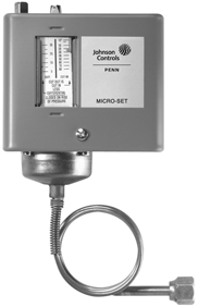
P70AB-12 MICRO-SET
Low Pressure Control
Repair Information
If the P70, P72, and P170 Series Controls for Low Pressure Applications fail to operate within their specifications, replace the units. For a replacement control, contact the nearest Johnson Controls® representative.
Standard Electromechanical Pressure Controls
![]() P70, P72, and P170 Series Controls for Low Pressure Applications (Continued)
P70, P72, and P170 Series Controls for Low Pressure Applications (Continued)
![]()
![]()
![]()
Selection Chart for Standard P70, P72, and P170 Controls for Low Pressure Applications
Note: To order models not listed in the selection chart, please contact Johnson Controls/PENN® Refrigeration Application Engineering at 1-800-275-5676.
Technical Specifications
Single Pressure Controls Switch Action, Low Event, High Event, and Models
| Switch and Action | Low Event | High Event | Models |
| SPST Open Low | Cut-Out
(Opens Line to M1) |
Cut-In
(Closes Line to M1) |
P70A, P70B, P170A |
| SPST Open High | Cut-In
(Closes Line to M1) |
Cut-Out
(Opens Line to M1) |
P70C, P70D, P170C, P170D |
| SPDT | Opens 1 to 2 and
closes 1 to 3 |
Closes 1 to 2 and
Opens 1 to 3 |
P70E, P70F |
| Four-Wire, Two-Circuits, 1 N.O., 1
N.C. Open Low |
Cut-Out
(Opens M2 to Line and Closes M1 to Line) |
Cut-In
(Closes M2 to Line and Opens M1 to Line) |
P70G, P70H |
| Four-Wire, Two-Circuits, 1 N.O., 1
N.C. Open High |
Cut-In
(Closes M2 to Line and Opens M1 to Line) |
Cut-Out
(Opens M2 to Line and Closes M1 to Line) |
P70J, P70K, P170K |
| DPST Open Low | Cut-Out
(Opens M1 to Line and M2 to Line) |
Cut-In
(Closes M1 to Line and M2 to Line) |
P72A, P72B |
| DPST Open High | Cut-In
(Closes M1 to Line and M2 to Line) |
Cut-Out
(Opens M1 to Line and M2 to Line) |
P72C, P72D |
Standard Electromechanical Pressure Controls
![]() P70, P72, and P170 Series Controls for Low Pressure Applications (Continued)
P70, P72, and P170 Series Controls for Low Pressure Applications (Continued)
![]()
![]()
![]()
L1 L2
![]()
![]()
Load
M1
Line
Open-Low switch action: opens on pressure drop.
(A and B Models) L1
![]()
![]()
![]()
Alarm
Load
2
1
3
L2
L1 L2
![]()
![]()
Load
M1
p7s_wir_spst.eps
p7s_wir_spdt.eps
Line
Open-High switch action: opens on pressure rise. (C and D Models)
1 to 3 opens, and 1 to 2 closes on pressure rise.
Typical Wiring for SPST Open Low Switch and Open High Switch (P70A, B, C, D, and P170A, C, D, Models)
Typical Wiring for SPDT Switch (P70E, F Models)
![]()
![]()
![]()
![]()
L1 L2
L3*
M2
Line
M1
Load
Line
Typical Wiring for Four-Wire Two-Circuit Switch (P70G and H Models)
eps 2.
4-
–
r
s_wi p7
![]()
![]()
![]()
![]()
L1
L2
Alarm
Alarm
Circuit Power
M1
Line
Load
Line
M2
Main circuit (Line to M2) opens and
auxiliary circuit (Line to M1) closes on pressure rise.
Line to M1 and Line to M2 open on pressure drop.
*(L3 is third supply line in three-phase applications.)
p7s_wir_dpst.eps
Typical Wiring for DPST Switch (P72A and B Models)
Standard Electromechanical Pressure Controls
![]() P70, P72, and P170 Series Controls for Low Pressure Applications (Continued)
P70, P72, and P170 Series Controls for Low Pressure Applications (Continued)
![]()
![]()
![]()
Technical Specifications (Continued)
SPST Electrical Ratings
(P70A, B, C, and D, and P170A, C, and D Models)
2-15/16
![]()
![]()
(74)
Two Mounting Holes 10-32 UNF-2B Thread
3-1/4
(83)
5/16
(9)
| Single-Phase Ratings | ||||
| Standard | Hermetic
Compressor |
|||
| 120
VAC |
208
VAC |
240
VAC |
208/240
VAC |
|
| Motor Horsepower | 2 | 3 | 3 | — |
| Motor Full-Load A | 24 | 18.7 | 17 | 20 |
| Motor Locked-Rotor A | 144 | 112.2 | 102 | 120 |
| Non-Inductive A | 22 | 22 | 22 | — |
| Pilot Duty | 125 VA, 120 to 600 VA; 57.5 VA,
120 to 300 VDC |
|||
5/16
(8)
3-1/4 (83)
1-11/16 (43)
5/16 (8)
1
(25)
1-1/8
(29)
1-7/8
13/16 (20)
1-3/4
(44)
Capillary or Connector as Specified
(48)
3/8
X 3/16 (5)
15/16
(24)
3/16 Diameter (5)
1-5/16 (34)
3-1/16
3/16 (5)
![]()
![]()
![]()
![]()
![]()
![]()
![]()
![]()
1-1/4 (32)
![]()
![]()
3/16 Diameter
(5) Mounting Hole
| Standard Single-Phase Ratings | ||||
| 120
VAC |
208
VAC |
240
VAC |
277
VAC1 |
|
| Motor Full Load A | 16.0 | 9.2 | 8.0 | 7.0 |
| Motor Locked Rotor A | 96.0 | 55.2 | 48.0 | 42.0 |
| Non-Inductive A | 16.0 | 9.2 | 8.0 | – |
| Pilot Duty | 125 VA at
120 to 600 VAC |
125 VA at
24 to 600 VAC |
||
Diameter
SPDT Electrical Ratings 1hp Switch (P70E Models)
1/16
(77)
4
7/8 or 1-1/8
(1/2 in. or 3/4 in. Trade Size)
(22) (28)
Conduit Hole
Dimensions for Low Pressure Controls with NEMA 1 Enclosure, in. (mm)*
p70_low_NEMA1_dims.eps
1. Rating for P70EC models only
SPDT Electrical Ratings 1/4 hp Switch (P70F Models)
5/8 (16)
![]()
![]()
![]()
![]()
![]()
![]()
![]()
![]()
![]()
79)
| Standard Single-Phase Ratings | |||
| 120 VAC | 208 VAC | 240 VAC | |
| Motor Full Load A | 6.0 | 3.3 | 3.0 |
| Motor Locked Rotor A | 36.0 | 19.8 | 18.0 |
| Non-Inductive A | 6.0 | 6.0 | 6.0 |
| Pilot Duty | 125 VA at 24 to 240 VAC | ||
4-1/16
(103) (
5/8 (16)
4-1/16
1/2
Four-Wire, Two-Circuit Electrical Ratings
7/16 (11)
(103)
2-11/16
3/8 (10)
3/4-NPSM
Threaded
| Standard Single-Phase Ratings | ||||||||
| Line-M2
(Main Contacts) |
Line-M1
(Auxiliary Contacts) |
|||||||
| 120
VAC |
208
VAC |
240
VAC |
277
VAC |
120
VAC |
208
VAC |
240
VAC |
277
VAC |
|
| Motor Full Load A | 16.0 | 9.2 | 8.0 | — | 6.0 | 3.3 | 3.0 | — |
| Motor Locked Rotor A | 96.0 | 55.2 | 48.0 | — | 36.0 | 19.8 | 18.0 | — |
| Non-Inductive A | 16.0 | 9.2 | 8.0 | 7.2 | 6.0 | 6.0 | 6.0 | 6.0 |
| Pilot Duty
for both sets of contacts |
125 VA at 24 to 600 VAC; 57.5 VA at 120 to 300 VDC | |||||||
(13)
(70)
2-15/16 3/16
(P70G, H, J, and K, and P170K Models)
1-1/4 (32)
(68)
(25)
1-9/16
Rigid Conduit
Connector
Four Mounting Holes
(74)
5/16 (8)
Diameter
(5)
1-3/4 (44)
1/2 (13)
p70_low_NEMA3R_dims.eps
Dimensions for Low Pressure Controls with NEMA 3R Enclosure, in. (mm)*
* These dimensions are nominal and are subject to accepted manufacturing tolerances and application variables.
DPST Electrical Ratings (P72A, B, C, and D Models)
| Standard Ratings | Hermetic Compressor Ratings | ||||||
| 120 VAC,
Single-Phase |
208 VAC,
Single-Phase |
240 VAC,
Single-Phase |
208 VAC,
Three-Phase |
220 VAC,
Three-Phase |
208 VAC,
Single-Phase |
240 VAC,
Single-Phase |
|
| Motor Horsepower | 2 | 3 | 3 | 5 | 5 | — | — |
| Motor Full-Load A | 24 | 18.7 | 17 | 15.9 | 15 | 24 | 24 |
| Motor Locked-Rotor A | 144 | 112.2 | 102 | 95.4 | 90 | 144 | 144 |
| AC Non-Inductive A | 24 | 24 | 24 | 24 | 24 | — | — |
| DC Non-Inductive A | 3 | 0.5 | 0.5 | 0.5 | 0.5 | — | — |
| Pilot Duty | 125 VA at 120 to 600 VAC; 57.5 VA at 120 to 300 VDC | ||||||
Standard Electromechanical Pressure Controls Code No. LIT-1900171
 P70, P72, and P170 Series Controls for High Pressure Applications
![]()
![]()
![]()
Description
The P70, P72, and P170 Controls for high pressure applications are designed primarily for high pressure cut-out control,
head-pressure control, and condenser fan cycling control on commercial refrigeration and air conditioning applications.
Controls are available in several pressure ranges and are compatible with most common refrigerants. They may also be used on other non-corrosive fluid applications. Ammonia compatible models are also available.
Several different electrical ratings and switch configurations are available. The P72 models provide direct control of 208-240 volt
single-phase motors up to 3 horsepower, and 208-220 volt 3-phase motors up to
5 horsepower.
Refer to the P70, P72, and P170 Series Controls for High Pressure Applications Product/Technical Bulletin (LIT-125454) for important product application information.
Features
• all-steel case and cover provides long lasting, rugged protection for internal components
• sight-set calibrated pressure adjustment displays a visible pressure scale, fully adjustable through the range without removing the cover (on NEMA 1 enclosure models)
Selection Chart (Part 1 of 2)
• manual reset lockout option provides
trip-free lockout that cannot be overridden or reset until pressure returns to specified level
• variety of available pressure connection styles allows greater flexibility when mounting control and adapting pressure connections to field application requirements
Applications
• P70C, P70D P170C and P170D models with single-pole, single-throw (SPST) Open High switch action are the most popular models, and are typically used for high-pressure cutout. The C models are automatic reset. The D models have a manual reset lockout mechanism. Some P70C, P70D P170C and P170D models are UL Listed as refrigeration pressure limiting controls.
• P70A and P170A models are available with SPST Open Low switch action, and typically are used for condenser fan cycling control.
• P70 and P170 models with single-pole, double-throw (SPDT), or four-wire,
two-circuit switch action allow users to install alarm devices or other control circuits.
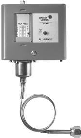
P70CA-3 High Pressure Cutout Control
• P72 models have a double-pole, single-throw (DPST) switch with
load-carrying contacts that can provide direct control of 208-240 V single-phase motors up to 3 horsepower, and 208-220 V 3-phase motors up to 5 horsepower. See the DPST Electrical Ratings (P72A, B, C, and D Models) that follow.
NEMA 1 enclosures are standard on most models.
Repair Information
If the P70, P72, and P170 Series Controls for High Pressure Applications fail to operate within their specifications, replace the units. For a replacement control, contact the nearest Johnson Controls® representative.
| Product Code
Number |
Switch
Action |
Range
psi (kPa) |
Differential
psi (kPa) |
Pressure
Connection |
Max. Working
Pressure |
| Condenser Fan Cycling Controls (for Non-Corrosive Refrigerants) | |||||
| P70AA-118C | SPST Open Low | 100 to 400 | Minimum 35 (241) Maximum 200 (1,379) | 36 in. Capillary
with 1/4 in. Flare Nut |
475 psig
(3,275 kPa) |
| P72AA-27C | DPST Open Low | ||||
| P170AA-118C | SPST Open Low | 1/4 in. External Flare Connector | |||
| All Range Controls (for Non-Corrosive Refrigerants) | |||||
| P70CA-2C1 | SPST Open High | 50 to 500
(345 to 3,448) |
Minimum 60 (414); Maximum 150 (1,034) | 1/4 in. External Flare Connector | 525 psig
(3,620 kPa) |
| P70CA-3C1 | 36 in. Capillary
with 1/4 in. Flare Nut |
||||
| P70DA-1C1 | Manual Reset Lockout | ||||
| P70KA-1C | Four-wire, Two-circuit | ||||
| P72CA-2C1 | DPST Open-high | Minimum 60 (414); Maximum 150 (1,034) | |||
| P72DA-1C1 | Manual Reset Lockout | ||||
| P170CA-3C1 | SPST Open High | Minimum 60 (414); Maximum 150 (1,034) | 1/4 in. External Flare Connector | ||
| P170DA-1C | Manual Reset Lockout | ||||
| P170KA-1C | Four-wire, Two-circuit
Line-M1 Close High Line-M2 Open High |
||||
Standard Electromechanical Pressure Controls
![]() P70, P72, and P170 Series Controls for High Pressure Applications (Continued)
P70, P72, and P170 Series Controls for High Pressure Applications (Continued)
![]()
![]()
![]()
Selection Chart (Part 2 of 2)
| Product Code
Number |
Switch
Action |
Range
psi (kPa) |
Differential
psi (kPa) |
Pressure
Connection |
Max. Working
Pressure |
| Models for High Pressure Non-Corrosive Refrigerants2 | |||||
| P70AA-2C | SPST Open Low | 0 to 150 (0 to 1,034) | Minimum 10 (69); Maximum 70 (483) | 36 in. Cap. with 1/4 in. Flare Nut | 325 psig |
| P170AA-2C | 1/4 in. External Flare Connector | ||||
| P70AA-400C | 100 to 470 | Minimum 35 (241); Maximum 200 (1,379) | 36 in. Cap. with 1/4 in. Flare Nut | 690 psig
(4,757 kPa) |
|
| P170AA-400C | 1/4 in. External Flare Connector | ||||
| P70CA-400C1 | SPST Open High | 200 to 610
(1,379 to 4,206) |
Minimum 60 (414); Maximum 150 (1,034) | 36 in. Cap. with 1/4 in. Flare Nut | |
| P170CA-400C1 | 1/4 in. External Flare Connector | ||||
| P70DA-400C1 | Manual Reset Lockout | 36 in. Cap. with 1/4 in. Flare Nut | |||
| P170DA-400C1 | 1/4 in. External Flare Connector | ||||
| Ammonia Compatible Models | |||||
| P70AA-119C | SPST Open Low | 50 to 300 (345 to 2,068) | Minimum 20 (138); Maximum 120 (827) | 1/4 in. SS Internal NPT | 400 psig
(2,758 kPa) |
| P70CA-5C1 | SPST Open-High | 50 to 500
(345 to 3,448) |
Minimum 60 (414); Maximum 150 (1,034) | 525 psig
(3,620 kPa) |
|
| P70DA-2C1 | Manual Reset Lockout | ||||
| P70KA-7C | Four-wire, Two-circuit
Line-M1 Close-high Line-M2 Open High |
||||
Note: To order models not listed in the selection chart, please contact
Johnson Controls/PENN Refrigeration Application Engineering at 1-800-275-5676.
Technical Specifications
Single Pressure Controls Switch Action, Low Event, High Event, and Models
| Switch and Action | Low Event | High Event | Models |
| SPST Open Low | Cut-Out (Opens Line to M1) | Cut-In (Closes Line to M1) | P70A, P70B, P170A |
| SPST Open High | Cut-In (Closes Line to M1) | Cut-Out (Opens Line to M1) | P70C, P70D, P170C, P170D |
| SPDT | Opens 1 to 2 and closes 1 to 3 | Closes 1 to 2 and Opens 1 to 3 | P70E, P70F |
| Four-wire, Two-circuits, 1 N.O., 1 N.C. Open Low | Cut-Out
(Opens M2 to Line and Closes M1 to Line) |
Cut-In
(Closes M2 to Line and Opens M1 to Line) |
P70G, P70H |
| Four-wire, Two-circuits,
1 N.O., 1 N.C. Open High |
Cut-In
(Closes M2 to Line and Opens M1 to Line) |
Cut-Out
(Opens M2 to Line and Closes M1 to Line) |
P70J, P70K, P170K |
| DPST Open Low | Cut-Out (Opens M1 to Line and M2 to Line) | Cut-In (Closes M1 to Line and M2 to Line) | P72A, P72B |
| DPST Open High | Cut-In (Closes M1 to Line and M2 to Line) | Cut-Out (Opens M1 to Line and M2 to Line) | P72C, P72D |
Standard Electromechanical Pressure Controls
![]() P70, P72, and P170 Series Controls for High Pressure Applications (Continued)
P70, P72, and P170 Series Controls for High Pressure Applications (Continued)
![]()
![]()
![]()
L1 L1
![]()
![]()
![]()
![]()
![]()
![]()
![]()
Alarm
Load
2
1
3
L2 L2
Load
Line
M1
Open-Low switch action: opens on pressure drop. (A and B Models)
p7s_wir_spdt.eps
L1 L2
![]()
![]()
![]()
Load
1 to 3 opens, and 1 to 2 closes on pressure rise.
Typical Wiring for SPDT Switch (P70E, F Models)
M1
p7s_wir_spst.eps
Line
Open-High switch action: opens on pressure rise. (C and D Models)
L1 L2
*L3
![]()
![]()
![]()
![]()
![]()
Line
M2
Load
Line
M1
Typical Wiring for SPST
(P70A, B, C, D, and P170A, C, D, Models)
L1 L2
![]()
![]()
![]()
![]()
![]()
Alarm
Alarm
Circuit Power
M1
Line
Load
Line
M2
p7s_wir_dpst.eps
Line to M1, and Line to M2 open on pressure rise.
*(L3 is third supply line in 3-phase applications.)
Typical Wiring for DPST Switch (P72C, and D Models)
Main circuit (Line to M2) opens and auxiliary circuit (Line to M1) closes on pressure rise.
p7s_wir-4-2.eps
Typical Wiring for Four-Wire Two-Circuit Switch used for a High Pressure Cutout Application with an Alarm Circuit (P70J, K, and P170K Models)
Standard Electromechanical Pressure Controls
![]() P70, P72, and P170 Series Controls for High Pressure Applications (Continued)
P70, P72, and P170 Series Controls for High Pressure Applications (Continued)
![]()
![]()
![]()
Technical Specifications (Continued)
![]()
![]()
![]()
![]()
![]()
![]()
![]()
![]()
![]()
![]()
![]()
![]()
2-15/16
Two Mounting Holes 10-32 UNF-2B Thread
3-1/4
(83)
5/16
(8)
5/16
(8)
3-1/4 (83)
1-11/16 (43)
5/16
1
(25)
1-1/16 (29)
15/16 (24)
15/16 (24)
Capillary or Connector as speci?ed
3/16 (5)
3/8 X 3/16
3/16 Diameter
(5)
(48)
(10) (5)
Mounting Hole
Diameter Mounting Hole
3/16 Diameter
(5)
2-1/16
(53) 15/16
(24)
1-5/16
1-1/4 (33)
1/16 (2)
(34) 3-1/16
(77) 4
101
(22) (28)
7/8 or 1-1/8 (1/2 in. or 3/4 in. Trade Size)
1-7/8
Dimensions for High Pressure Controls with NEMA 1 Enclosure, in. (mm)*
p7shi_dim1.eps
SPST Electrical Ratings
(P70A, B, C, and D, and P170A, C, and D Models)
| Single-Phase Ratings | ||||
| Standard | Hermetic
Compressor |
|||
| 120
VAC |
208
VAC |
240
VAC |
208/240
VAC |
|
| Motor Horsepower | 2 | 3 | 3 | — |
| Motor Full-Load A | 24 | 18.7 | 17 | 24 |
| Motor Locked-Rotor A | 144 | 112.2 | 102 | 144 |
| Non-Inductive A | 22 | 22 | 22 | — |
| Pilot Duty | 125 VA at 120 to 600 VAC; 57.5 VA at
120 to 300 VDC |
|||
SPDT Electrical Ratings 1hp Switch (P70E Models)
| Standard Single-Phase Ratings | ||||
| 120
VAC |
208
VAC |
240
VAC |
277
VAC1 |
|
| Motor Full Load A | 16.0 | 9.2 | 8.0 | 7.0 |
| Motor Locked Rotor A | 96.0 | 55.2 | 48.0 | 42.0 |
| Non-Inductive A | 16.0 | 9.2 | 8.0 | – |
| Pilot Duty | 125 VA at
120 to 600 VAC |
125 VA at
24 to 600 VAC |
||
1. Rating for P70EC models only
Dimensions for High Pressure Controls with NEMA 3R Enclosure, in. (mm)*
![]()
![]()
![]()
![]()
![]()
![]()
![]()
![]()
![]()
![]()
![]()
![]()
![]()
![]()
5/8 (16)
4-1/16 (104)
3-1/8 (79)
5/8
5/8 (15)
4-1/16 (104)2-11/16
(68) 1
(25)
3/8 (10)
1/2 (12)
3/4-NPSM
Threaded Rigid Conduit
2-3/4
(70)
2-15/16
(74)
3/16 (5)
Connector
Four Mounting Holes
5/16 Diameter
(8)
1-1/4 (31)
1-9/16 (40)
15/16 (24)
1/2 (13)
(16)
p7shi_dim3.eps
* These dimensions are nominal and are subject to accepted manufacturing tolerances and application variables.
SPDT Electrical Ratings1/4 hp Switch (P70F Models)
| Standard Single-Phase Ratings | |||
| 120 VAC | 208 VAC | 240 VAC | |
| Motor Full Load A | 6.0 | 3.3 | 3.0 |
| Motor Locked Rotor A | 36.0 | 19.8 | 18.0 |
| Non-Inductive A | 6.0 | 6.0 | 6.0 |
| Pilot Duty | 125 VA at 24 to 240 VAC | ||
Four-wire, Two-circuit Electrical Ratings (P70G, H, J, and K, and P170K Models)
| Standard Single-Phase Ratings | ||||||||
| Line-M2
(Main Contacts) |
Line-M1
(Auxiliary Contacts) |
|||||||
| 120
VAC |
208
VAC |
240
VAC |
277
VAC |
120
VAC |
208
VAC |
240
VAC |
277
VAC |
|
| Motor Full Load A | 16.0 | 9.2 | 8.0 | — | 6.0 | 3.3 | 3.0 | — |
| Motor Locked Rotor A | 96.0 | 55.2 | 48.0 | — | 36.0 | 19.8 | 18.0 | — |
| Non-Inductive A | 16.0 | 9.2 | 8.0 | 7.2 | 6.0 | 6.0 | 6.0 | 6.0 |
| Pilot Duty for both
sets of contacts |
125 VA at 24 to 600 VAC; 57.5 VA at 120 to 300 VDC | |||||||
DPST Electrical Ratings (P72A, B, C, and D Models)
| Standard Ratings | Hermetic Compressor Ratings | ||||||
| 120 VAC,
Single-Phase |
208 VAC,
Single-Phase |
240 VAC,
Single-Phase |
208 VAC,
Three-Phase |
220 VAC,
Three-Phase |
208 VAC,
Single-Phase |
240 VAC,
Single-Phase |
|
| Motor Horsepower | 2 | 3 | 3 | 5 | 5 | — | — |
| Motor Full-Load A | 24 | 18.7 | 17 | 15.9 | 15 | 24 | 24 |
| Motor Locked-Rotor A | 144 | 112.2 | 102 | 95.4 | 90 | 144 | 144 |
| AC Non-Inductive A | 24 | 24 | 24 | 24 | 24 | — | — |
| DC Non-Inductive A | 3 | 0.5 | 0.5 | 0.5 | 0.5 | — | — |
| Pilot Duty | 125 VA at 120 to 600 VAC; 57.5 VA at 120 to 300 VDC | ||||||
Standard Electromechanical Pressure Controls Code No. LIT-1900172
 P70, P72, and P170 Series Controls for Dual Pressure Applications
![]()
![]()
![]()
Description
The P70, P72, and P170 Controls for Dual Pressure Applications are designed primarily for use as combination high and low pressure controls on commercial refrigeration and air conditioning applications.
These controls are available in several pressure ranges and are compatible with most common refrigerants. Ammonia compatible models are also available.
These controls respond directly to system pressure changes on both high and low sides, and can provide single-device control of the compressor.
Controls are available in several different electrical ratings and switch configurations, including independent high and low pressure switches (on P70S and P170S models). The P72 models provide direct control of
208 to 240 volt, single-phase motors up to three horsepower, and 208 to 220 volt, three-phase motors up to five horsepower.
Refer to the P70, P72, and P170 Series Controls for Dual Pressure Applications Product Bulletin (LIT-125455) for important product application information.
Features
• all-steel case and cover built to provide long lasting, rugged protection for internal components
• sight-set calibrated pressure adjustment displays a visible pressure scale, fully adjustable through the range without removing the cover (on NEMA 1 enclosure models)
Selection Chart (Part 1 of 2)
• MICRO-SET™ differential option allows for precise control on low pressure applications
• independent high and low pressure switches (P70S and P170S Models) satisfies a variety of dual pressure application wiring requirements with a single versatile control
• convertible high pressure reset–auto reset or manual reset lockout (P70S and P170S Models) reduces inventory—one control can be adapted to several dual pressure applications in the field
Applications
• P70S and P170S models have independently operated high and low pressure single-pole, double-throw (SPDT) switches that can be wired to satisfy a variety of control requirements. These adaptable controls also come with a high pressure manual reset lockout mechanism that may be converted to automatic reset.
• P70L, M, N, and P170L, M, N models have a single-pole, single-throw (SPST) switch. Models are available with automatic or manual reset lockout options. Models with manual reset are available with either high-side-only manual reset, or low-side and high-side manual reset. Ammonia-compatible models are also available (P70L and P70M only).
• P72 models have a double-pole, single-throw (DPST) switch with
load-carrying contacts that can provide direct control of 208 to 240 VAC,
single-phase motors up to 3 hp, and 208 to 220 VAC, three-phase motors up to 5 hp. See the DPST Electrical Ratings (P72L, M, and N Types) that follow.
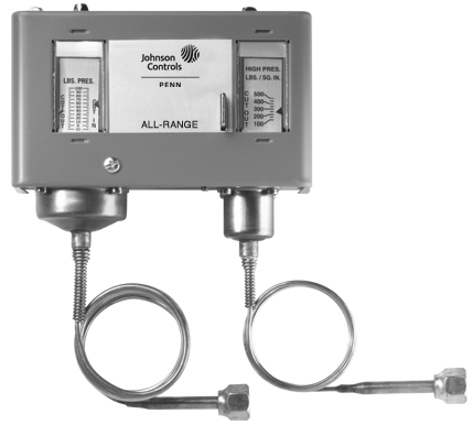
P70MA-1 Dual Pressure Control
Some models are available with Limited Knob Adjustment, which restricts adjustment of the pressure settings and deters
over-adjustment or tampering.
NEMA 1 enclosures are standard on most models. NEMA 3R enclosures are also available.
Repair Information
If the P70, P72, and P170 Series Controls for Dual Pressure Applications fail to operate within its specifications, replace the unit. For a replacement control, contact the nearest Johnson Controls® representative.
| Product Code
Number |
Switch
Action |
Low Pressure Side psi (kPa) | High Pressure Side psi (kPa) | Pressure
Connector |
Limited Knob
Adjustment |
||
| Range | Differential | Range | Differential (Non-Adjustable) | ||||
| MICRO-SET Controls for Non-Corrosive Refrigerants | |||||||
| P70LB-6C1 | SPST | 12 in.Hg
to 80 |
Minimum 5 (34)
Maximum 35 (241) |
100 to 500
(690 to 3,447) |
Fixed approx. 65 (448) | 36 in.
capillary with 1/4 in. flare nut |
Low cut-out |
| P70MA-1C1 | Lockout requires manual reset | None | |||||
| P70SA-1C1 | Two independent | Fixed at 65 (448) or
Lockout requires manual reset |
|||||
| P170LB-6C1 | SPST | Fixed approx. 65 (448) | 1/4 in. | Low cut-out | |||
| P170MA-18C1 | Lockout requires manual reset | None | |||||
| P170SA-1C1 | Two independent
SPDT |
Fixed at 65 (448) or
Lockout requires manual reset |
|||||
| All Range Controls for Non-Corrosive Refrigerants | |||||||
| P70LB-1C1 | SPST | 20 in.Hg
to 100 |
Minimum 6 (41)
Maximum 50 (345) |
100 to 500
(690 to 3,447) |
Fixed Approx. 65 (448) | 36 in. | Low cut-out |
| P70MA-1C1 | Lockout Requires Manual Reset | None | |||||
| P70NA-1C | Fixed (manual reset) | ||||||
| P72LA-1C1 | DPST | Minimum 7 (48)
Maximum 50 (345) |
Fixed approx. 65 (448) | ||||
| P72LB-1C1 | Low cut-out | ||||||
| P72MA-1C1 | Lockout requires manual reset | None | |||||
| P72NA-1C1 | Fixed (manual reset) | ||||||
Standard Electromechanical Pressure Controls
![]() P70, P72, and P170 Series Controls for Dual Pressure Applications (Continued)
P70, P72, and P170 Series Controls for Dual Pressure Applications (Continued)
![]()
![]()
![]()
Selection Chart (Part 2 of 2)
| Product Code
Number |
Switch
Action |
Low Pressure Side psi (kPa) | High Pressure Side psi (kPa) | Pressure
Connector |
Limited Knob
Adjustment |
||
| Range | Differential | Range | Differential (Non-Adjustable) | ||||
| All Range Controls for Non-Corrosive Refrigerants | |||||||
| P170LB-1C1 | SPST | 20 in.Hg
to 100 |
Minimum 7 (48)
Maximum 50 (345) |
100 to 500
(690 to 3,447) |
Fixed approx. 65 (448) | 1/4 in.
External flare connector |
Low cut-out |
| P170MA-1C1 | Lockout requires manual reset | None | |||||
| P170NA-1C | Fixed (manual reset) | ||||||
| All Range Ammonia Compatible Controls | |||||||
| P70LA-2C1 | SPST | 20 in. Hg to
100 (-68 to 690) |
Minimum 7 (48)
Maximum 50 (345) |
100 to 500
(690 to 3,447) |
Fixed approx. 65 (448) | 1/4 in.
Internal NPT connector |
None |
| P70MA-2C1 | Lockout requires manual reset | ||||||
1. Control models with high pressure side (only) that are UL Listed as Refrigeration Pressure Limiting Controls.
Note: For information on models not listed, please contact Johnson Controls/PENN® Refrigeration Application Engineering at 1-800-275-5676.
Technical Specifications
Maximum Pressures
| Pressure | Low Side | High Side | |
| All Range | MICRO-SET | ||
| Maximum Working Pressure | 100 psi (552 kPa) | 80 psi (690 kPa) | 500 psi (3,447 kPa) |
| Maximum Overpressure | 325 psi (2,241 kPa) | 525 psi (3,620 kPa) | 525 psi (3,620 kPa) |
L1 L1
![]()
![]()
![]()

L2 L2
L1 L2
L3*
![]()
![]()
![]()
![]()
![]()
![]()
High side opens Line to M1 on pressure rise.
High
c
Load a
c o
p7sdual_wir_spst.eps
t High
r
Line
M2
| High side opens Main ircuit (Line to M2), nd closes auxiliary ircuit (Line to M1)
n pressure rise. ow side opens Main |
Alarm Alarm Circui
Powe High Load Line M1 |
|
High side opens
Line to M1 and Line to M2 on pressure rise.
M1
p7sdual_wir_pst.eps
M1
Line L
Line M2
Line
p7sdual_wir_4-2.eps
Load
Low side opens Line
to M1 on pressure drop.
Low
circuit (Line to M2), and closes auxiliary circuit (Line to M1)
Low
Low side opens Line to M1 and Line to M2 on pressure drop.
Typical Wiring for SPST Switch
on pressure drop.
Low
*(L3 is third supply line in 3-phase applications.)
(P70L, M, and N, and P170L, M, and N Models)
Typical Wiring for Four-Wire, Two-Circuit Switch (P70P, Q and R Models)
Typical Wiring for DPST Switch (P72L, M, and N Models)
L1 L2
![]()
![]()
![]()
![]()
![]()
![]()
Low
Alarm
High
Alarm
Load
2
3
1 1
3
2
Low
High
L1 L2
1
![]()
![]()
![]()
![]()
![]()
![]()
![]()
![]()
High side switch opens 1 to 2 and closes 1 to 3 on pressure rise.
1
High
High Alarm
3
2
2
Low Load
High Load
Low Alarm
p7sdual_wir_2spdt_-diff.eps
Low side switch opens 1 to 2 and closes 1 to 3 on pressure drop.
High side switch opens 1 to 2 and closes 1 to 3 on pressure rise.
Low side switch opens 1 to 2 and closes 1 to 3 on pressure drop.
3
Low
Two SPDT Switches Wired as a Dual Pressure Control (Switching a Single Load with Optional High Side Alarm and Low Side Alarm) (P70S and P170S Models)
p7sdual_wir_2spdt_asdual.eps
Two SPDT Switches Wired to Control Two Different Loads (Optional High Side Alarm and Low Side Alarm) (P70S and P170S Models)
Standard Electromechanical Pressure Controls
![]() P70, P72, and P170 Series Controls for Dual Pressure Applications (Continued)
P70, P72, and P170 Series Controls for Dual Pressure Applications (Continued)
![]()
![]()
![]()
Technical Specifications (Continued)
DPST Electrical Ratings (P72L, M, and N Types)
| Standard Ratings | Hermetic Compressor Ratings | ||||||
| 120 VAC,
Single-Phase |
208 VAC,
Single-Phase |
240 VAC,
Single-Phase |
208 VAC,
Three-Phase |
220 VAC,
Three-Phase |
208 VAC,
Single-Phase |
240 VAC,
Single-Phase |
|
| Motor Horsepower | 2 | 3 | 3 | 5 | 5 | — | — |
| Motor Full-Load A | 24 | 18.7 | 17 | 15.9 | 15 | 24 | 24 |
| Motor Locked-Rotor A | 144 | 112.2 | 102 | 95.4 | 90 | 144 | 144 |
| AC Non-Inductive A | 24 | 24 | 24 | 24 | 24 | — | — |
| DC Non-Inductive A | 3 | 0.5 | 0.5 | 0.5 | 0.5 | — | — |
| Pilot Duty | 125 VA at 120 to 600 VAC; 57.5 VA at 120 to 300 VDC | ||||||
SPST Electrical Ratings (P70L, M, and N, and P170L, M, and N Types)
![]()
![]()
![]()

![]()
![]()
![]()
![]()
![]()
![]()
![]()
5/16
(15) 2-7/8
(73)
Reset Button for Controls with both High and Low Side Reset
Two Mounting Holes 10-32 UNF-28 Thread
5
![]()
![]()
![]()
![]()
![]()
![]()
![]()
![]()
![]()
5/16
3/16 Diameter
| Single-Phase Ratings | ||||
| Standard | Hermetic
Compressor |
|||
| 120
VAC |
208
VAC |
240
VAC |
208/240
VAC |
|
| Motor Horsepower | 2 | 3 | 3 | — |
| Motor Full-Load A | 24 | 18.7 | 17 | 24 |
| Motor Locked-Rotor A | 144 | 112.2 | 102 | 144 |
| Non-Inductive A | 22 | 22 | 22 | — |
| Pilot Duty | 125 VA at 120 to 600 VAC; 57.5 VA at
120 to 300 VDC |
|||
(5) Mounting Hole
(127)
5/16
(8)
(9)
3-1/4
(83)
13/16
(20)
1-11/16 (43)
15/16
(95)
11/16 15/16
1
(25)
1-1/8 (29)
1-3/4
(17)
(95)
(44)
3/16 (4)
1-11/16 (43)
Reset Lever for Controls
with High Side Only Manual Reset (Except P70S and P170S Models)
1-15/16
(48)
2-1/16
5/16
3/16
3/8 X 3/16 Diameter
(53) 1 5/16
(33) 15/16
(24)
(8)
(5)
(10) (5) Mounting Hole
SPDT Electrical Ratings
1-5/16
(33) 3
3-3/16 (80)
11/16 (18)
p7sdual_dim1.eps
1/16
(76)
5-11/16
7/8 or 1-1/8 (1/2 in. or 3/4 in. Trade Size)
(P70S and P170S Types)
(2)
(144)
(22) (28) Conduit Hole
Dimensions for P70, P72, and P170 Dual Pressure Controls with NEMA 1 Enclosure, in. (mm)*
| Standard Single-Phase Ratings | ||||
| 120
VAC |
208
VAC |
240
VAC |
277
VAC |
|
| Motor Full Load A | 16.0 | 9.2 | 8.0 | 7.0 |
| Motor Locked Rotor A | 96.0 | 55.2 | 48.0 | 42.0 |
| Non-Inductive A | 16.0 | 9.2 | 8.0 | – |
| Pilot Duty | 125 VA at 24 VAC; 720 VA at 120 to
277 VAC |
|||
Four-Wire, Two-Circuit Electrical Ratings (P70P, Q, and R Types)
5/8 (16)
5/8 (16)
3-1/8 (79)
4-13/16 (122)
5-13/16
| Standard Single-Phase Ratings | ||||||||
| Line-M2
(Main Contacts) |
Line-M1
(Auxiliary Contacts) |
|||||||
| 120
VAC |
208
VAC |
240
VAC |
277
VAC |
120
VAC |
208
VAC |
240
VAC |
277
VAC |
|
| Motor Full
Load A |
16.0 | 9.2 | 8.0 | — | 6.0 | 3.3 | 3.0 | — |
| Motor Locked Rotor A | 96.0 | 55.2 | 48.0 | — | 36.0 | 19.8 | 18.0 | — |
| Non- Inductive A | 16.0 | 9.2 | 8.0 | 7.2 | 6.0 | 6.0 | 6.0 | 6.0 |
| Pilot Duty for both sets of contacts | 125 VA at 24 to 600 VAC; 57.5 VA at 120 to 300 VDC | |||||||
(148) 4-7/16
(112) 2-3/4
(69)
1-1/4
(32)
3/8
(10)
2-3/4
(70)
3-3/8 (86)
Four Mounting Holes 5/16 Diameter
(8)
1/16 (2)
1-3/8
3/4-NPSM Threaded Rigid Conduit Connector
1-1/8 1-3/4
p7sdual_dim3.eps
(35)
Element as Specified
7/16 (10)
![]()
![]()
![]()
![]()
![]()
![]()
![]()
![]()
![]()
![]()
![]()
![]()
![]()
![]()
![]()
![]()
![]()
![]()
![]()
(29)
(44)
Dimensions for P70, P72, and P170 Dual Pressure Control with NEMA 3R Enclosure, in. (mm)*
*These dimensions are nominal and are subject to accepted manufacturing tolerances and application variables.
Single-Stage Electronic Pressure Controls Code No. LIT-1900109
 P470 Electronic Pressure Control with Display
![]()
![]()
![]()
Description
The P470 Electronic Pressure Control with Display is a single-stage, On/Off, electronic pressure control with a single-pole,
double-throw (SPDT) output relay. The control may be field set to operate in one of
three pressure ranges (0 to 100 psi, 0 to 500 psi, or 50 to 750 psi), as either an open high or open low control.
The P470 Control features a large LCD that displays the sensed pressure and other system-status indicators, as well as the adjustable setpoints in the programming mode. The P470 Control has a lockable, three-button touchpad for adjusting setpoints, and a front-panel LED that indicates the output relay status.
The P470 Control uses a P499 Electronic Pressure Transducer in conjunction with a WHA-PDK3 Wiring Harness to sense system pressure. This arrangement virtually eliminates the chance of a refrigerant leak because there are no capillaries or bellows to break or fail.
Refer to the P470 Electronic Pressure Control with Display Product Bulletin (LIT-125528) for important product application information.
Selection Chart
Features
• easy-to-read LCD
• three field-selectable pressure ranges between 0 to 750 psi
• 24 VAC, and 120 or 208/240 VAC models
• lockable, three-button, front-panel touchpad
• built-in, adjustable, anti-short cycle time-delay
• uses an economical and versatile transducer and wiring harness
Repair Information
The P470 pressure control and
P499 transducer are not field repairable. Perform the following procedures, in the order they are presented, to determine the problem. If the problem is with the control or transducer, contact a Johnson Controls/PENN® sales representative for a replacement.
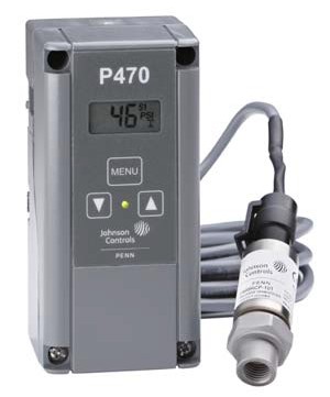
P470 Pressure Control with Transducer and Wiring Harness (Control, Transducer, and Harness Must be Purchased Separately)
| Item | Product Code Number | Description |
| P470 (Low-Voltage) Electronic
Pressure Control with Display |
P470FB-1C | Low Voltage (less than 30 VAC) Electronic Pressure Control with Display
Supply Voltage: 24 VAC Class 2 Transformer (See Technical Specifications for complete Relay Electrical Ratings.) |
| P470 (Line-Voltage) Electronic Pressure Control with Display | P470EB-1C | Line Voltage Electronic Pressure Control with Display Supply Voltage: 120 or 208/240 VAC
(See Technical Specifications for complete Relay Electrical Ratings.) |
| P499 Electronic Pressure Transducers | P499RAP-101C P499RAP-101K | 0 to 100 psi Pressure Transducer with 1/8 in. NPT External Fitting |
| P499RCP-101C P499RCP-101K | 0 to 100 psi Pressure Transducer with 1/4 in. SAE (Schrader®) Internal Fitting with integral valve depressor | |
| P499RAP-105C P499RAP-105K | 0 to 500 psi Pressure Transducer with 1/8 in. NPT External Fitting | |
| P499RCP-105C P499RCP-105K | 0 to 500 psi Pressure Transducer with 1/4 in. SAE (Schrader) Internal Fitting with integral valve depressor | |
| P499RAP-107C P499RAP-107K | 0 to 750 psi Pressure Transducer with 1/8 in. NPT External Fitting | |
| P499RCP-107C P499RCP-107K | 0 to 750 psi Pressure Transducer with 1/4 in. SAE (Schrader) Internal Fitting with integral valve depressor | |
| Wiring Harnesses for P499 Transducers | WHA-PKD3-200C | 6 ft 6-1/2 in. (2 m) 3-Wire Cable with Plug-in Connector for P499 Transducer |
| WHA-PKD3-400C | 13 ft 3 in. (4 m) 3-Wire Cable with Plug-in Connector for P499 Transducer | |
| WHA-PKD3-600C | 19 ft 8 in. (6 m) 3-Wire Cable with Plug-in Connector for P499 Transducer |
Note: P470 Controls do not include a transducer or wiring harness. P499 Transducer and wiring harness must be purchased separately. Transducer must be matched to the selected pressure range.
Single-Stage Electronic Pressure Controls
P470 Electronic Pressure Control with Display (Continued)
![]()
![]()
![]()
![]()
Output Relay Contacts Electrical Ratings
| P470EB-1 | P470 FB-1 | |||
| 120 VAC | 208 VAC | 240 VAC | 24 VAC | |
| Horsepower N.O. (N.C.) | 1 (1/4) | 1 (1/3) | 1 (1/2) | 100 VA,
30 VAC maximum, Class 2 |
| Full Load Ampere N.O. (N.C.) | 16 (5.8) | 9.2 (4.0) | 8.0 (4.9) | |
| Locked Rotor Ampere N.O. (N.C.) | 96 (34.8) | 55.2 (24) | 498 (29.4) | |
| Non-Inductive Ampere N.O. (N.C.) | 15 (10) | 10 (10) | 10 (10) | |
| Pilot Duty | 125 VA (N.O.) at 24 to 240 VAC
125 VA (N.C.) at 120 to 240 VAC 50 VA (N.C.) at 24 VAC |
|||
| P470 Electronic Pressure Control with Display | |||
| Operating Pressure Ranges | 0 to 100 psi | 0 to 500 psi | 50 to 750 psi |
| Minimum Differential Pressure | 5 psig | 20 psig | 20 psig |
| Displayed Resolution | 1 psig | 3 psig | 5 psig |
| Control Accuracy | + 1.5% of selected Operating Pressure Range plus transducer accuracy | ||
| Supply Voltage | P470FB-1:24 VAC, 50/60 Hz, Class 2 P470EB-1:120 or 208/240 VAC, 50/60 Hz | ||
| Power Consumption | 1.8 VA maximum | ||
| Transducer Type | P499 Electronic Pressure Transducer | ||
| Ambient Temperature at Control | Operating: -30 to 140°F (-34 to 60°C) Shipping: -40 to 185°F (-40 to 85°C) | ||
| Ambient Humidity at Operating Control | 0 to 95% RH noncondensing; Maximum dew point: 85°F (29°C) | ||
| Enclosure | Case and cover: NEMA 1 High-impact thermoplastic | ||
| Agency Information | UL: File SA516; CCN SDFY Canadian UL: File SA516; CCN SDFY7
FCC/DOC Part 15, Class A |
||
Electromechanical Lube Oil and Differential Pressure Controls Code No. LIT-1927185
 P28 Series Lube Oil Pressure Cutout Control with Time Delay
![]()
![]()
![]()
Description
The P28 series provides dependable lube oil protection on pressure of lubricated refrigeration compressors by sensing low lube oil pressure. A built-in time delay switch, accurately compensated for ambient temperature, allows for pressure pick up on start and avoids nuisance shutdowns on pressure drops of short duration during the running cycle.
Refer to the P28 and P128 Series Lube Oil Controls with Built-in Time Delay Relay Product Bulletin (LIT-125420) for important product application information.
Features
• direct-reading scale indication
• adjustable setpoint
• trip-free manual reset
• replacement timing relays available
• dust-protected switch
Applications
• semi-hermetic compressors
• P28 Control measures pressure available to circulate oil though the lubrication system (Net oil pressure is the difference between oil gauge and crankcase pressure.)
Accessories
• all models listed on this page include a universal mounting bracket
• replacement timing relays— refer to Replacement Timing Relays for P28 and P29 Lube Oil Controls Catalog Page (LIT-1927395)
Repair Information
If the P28 Series Lube Oil Pressure Cutout Control with Time Delay fails to operate within its specifications, replace the unit. For a replacement control, contact the nearest Johnson Controls® representative.
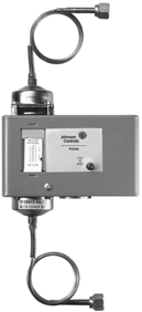
P28AA Lube Oil Pressure Cutout Control
Selection Chart
| Product Code | Time
Delay |
Time Delay
Heater Circuit VAC |
Type of
Reset |
Range1 psi (kPa) | Refrigerant
(R) |
Pressure
Connection |
| P28AA-1C2 | 90 seconds | 120/240 | Manual | 8 to 70 (55 to 483) | Non-corrosive3 | 36 in. capillary with
1/4 in. flare nut |
| P28AA-2C4 | 60 seconds | |||||
| P28AA-17C5 | 120 seconds | |||||
| P28AA-18C | 45 seconds | |||||
| P28AN-1C | 90 seconds | 120/240 | Manual | 8 to 70 (55 to 483) | Ammonia | 1/4 in. internal NPT |
| P28DN-1C | 90 seconds | |||||
| P28DA-1C | 120/240 | Manual | 8 to 70 (55 to 483) | Non-corrosive3 | 36 in. capillary with 1/4 in. flare nut | |
| P28GA-2C | 90 seconds | Automatic | ||||
| P28NA-5C | 120 seconds | 24 VAC
or VDC |
Manual |
- Switch differential approximately 5 psig (34 kPa). Time delay relay energizes at 9 psig (61 kPa) pressure difference, de-energized at 14 psig (97 kPa) difference
- Replaces Ranco® P30-3701
- Non-corrosive refrigerants include R-12, R-22, R-134A, R-500, R-502 (R)
- Replaces Ranco P30-3601
- Replaces Ranco P30-3801
Technical Specifications
The maximum bellows pressure is 180 psig (2,241 kPa).
Electrical Ratings – Pilot Duty
| Time Delay
Heater Circuit |
Pilot Circuit | Alarm Circuit
(must be same voltage as pilot circuit) |
P28DA-1 Contact Rating 2 to 1: 2 to 3
(must be same voltage as time delay circuit) |
|
| Crankcase Heater: Term 2 to 1 | Runlight: Term 2 to 3 | |||
| 120/240 VAC | 750 VA, 120/240 VAC | 125 VA, 120/240 VAC | 10 A 120 VAC, 5 A 240 VAC | 10 W |
| 24 VAC or VDC | 125 VA, 24 VAC
57.5 VA, 24 VDC |
125 VA, 24 VAC
57.5 VA, 24 VDC |
— | |
Electromechanical Lube Oil and Differential Pressure Controls Code No. LIT-1927195
 P32 Series Sensitive Pressure Switch
![]()
![]()
![]()
Description
This differential pressure switch is used to sense pressure/air flow in ducts.
Refer to the P32 Series Sensitive Differential Pressure Switch Product Bulletin
(LIT-125435) for important product application information.
P32 Series
![]()
![]()
![]()
![]()
![]()
Y
R
B
Action on Increase of Pressure
p32.eps
P28 Action Diagram
Selection Chart
![]()
![]()

![]()
![]()

Product
Code Number
Ambient
Temperature Min./Max.
Connector
Maximum
Over- pressure psig (kPa)1
Contact
Action
Range
in. WC (kPa)
Sensitivity
at Min.
Setpoint
in. WC (kPa)
Setpoint
Scale
Plate
Mounting Bracket
(Included)
P32AC-1C
-40°F (-40°C)
min.
167°F (75°C)
max.
High Pressure connectors are metal 1/8 in. internal NPT inside, 1/2 in. NPSM outside for mounting
Low pressure connectors are molded,
1/8 in. internal NPT
1
(6.895)
SPDT
0.15 to 12 (0.037 to 2.99)
0.07
(0.017)
Adjustable
Yes
L
P32AC-2C2
0.05 to 5 (0.012 to 1.24)
0.04
(0.01)
U
P32AF-1C
0.025
(0.006)
L
BKT182-1
P32AF-2C2
U
BKT229-1
bracket1.eps bracket2.eps bracket1.eps
bracket2.eps
Features
• easy-to-read setpoint scale
• versatile mounting options
Applications
• pressure/air flow proving with electric duct heaters, humidifiers, and other equipment
• maximum pressure/air flow control for variable volume systems
• reheat duct powered systems
• clogged filter detection
• detection of icing of air conditioning coils and initiation of defrost cycle
• sensitive pressure settings
• dust-tight snap switch
Repair Information
If the P32 Series Sensitive Pressure Switch fails to operate within its specifications, replace the unit. For a replacement switch, contact the nearest Johnson Controls® representative.
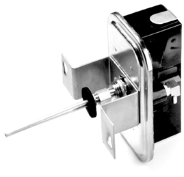
P32 Sensitive Pressure Switch
- Maximum overpressure at either connection
- Supplied with 1/4 in. compression fitting, 4 in. extension tube, two mounting screws, and O-gasket (angle barbed fitting installed)
Accessories
The switch can be mounted directly or with the supplied mounting bracket.
Technical Specifications
Electrical Ratings
| Motor Ratings VAC | 120 | 208 | 240 |
| Type P32AC (Standard Differential, 1/2 hp) | |||
| AC Full Load A | 9.8 | 5.65 | 4.9 |
| AC Locked Rotor A | 58.8 | 33.9 | 29.4 |
| Non-Inductive or Resistive Load | 15 A, 24 to 277 VAC | ||
| Pilot Duty | 125 VA, 24 VAC; 360 VA,
120 to 277 VAC |
||
| Type P32AF (Close Differential, 1/4 hp) | |||
| AC Full Load A | 5.8 | 3.3 | 2.9 |
| AC Locked Rotor A | 34.8 | 19.8 | 17.4 |
| Non-Inductive or Resistive Load | 10 A, 24 to 277 VAC | ||
| Pilot Duty | 125 VA, 24 VAC; 360 VA,
120 to 277 VAC |
||
| Product Code | Description |
| FTG18A-600R | Remote Mounting Kit: 4 in. flanged sensing tube,
two barbed fittings, two No. 10 screws, and a gasket |
Electromechanical Lube Oil and Differential Pressure Controls Code No. LIT-1927200
 P45 Series Lube Oil Pressure Cutout Control with Time Delay
![]()
![]()
![]()
Description
The P45 Control provides dependable, low lube oil pressure protection for refrigeration compressors. The low-adjustable factory-set pressure setting provides operation to the compressor manufacturer’s specification. A built-in time delay relay, compensated for ambient temperature, allows for pressure pick-up on start and avoids nuisance shutdowns on short duration pressure losses during the running cycle.
Refer to the P45 Series Oil Pressure Cutout Controls with Built-in Time Delay Relay Product Bulletin (LIT-125445) for important product application information.
Features
• universal mounting
• trip-free manual reset
• ambient compensated time delay
Selection Chart
Accessories
These controls are supplied without mounting brackets. If brackets are required, order kit number BKT38A-600R, which contains five 271-51 Angle Mounting Brackets with screws.
Applications
The P45 control is used on semi-hermetic compressors. It measures net oil pressure available to circulate oil through the compressor’s lubrication system. (Net oil pressure is the difference between oil pump pressure and the crank case pressure.)
Repair Information
If the P45 Series Lube Oil Pressure Cutout Control with Time Delay fails to operate within its specifications, replace the unit. For a replacement control, contact the nearest Johnson Controls® representative.
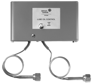
P45NCALube Oil Pressure Cutout Control
Technical Specifications For all non-corrosive refrigerants. Electrical Rating – Pilot Duty
| Time Delay
Heat Circuit |
Pilot Duty |
| 120/240 VAC | 750 VA, 120/240 VAC |
| 24 VAC | 125 VA, 24 VAC |
- Relay is not field-replaceable
- Switch differential is approximately 5 psi (34 kPa). Time delay relay energizes at 9 psi (61 kPa) pressure difference, de-energizes at 14 psi (97 kPa) difference.
- Replaces Ranco® P30-5826
- Replaces Ranco P30-5827
- Replaces Ranco P30-5827 (Includes alarm wire)
- Replaces Carlyle/Carrier® Code No. HKCA-500, 6342050
- Switch differential is approximately 4.5 psi (34 kPa). Time delay relay energizes at 6.5 psi (45 kPa) pressure difference, de-energizes at 11 psi (76 kPa) difference.
- Replaces Carlyle/Carrier Part No. HKCA-500, 6342050 with 36” SEC99A UltraCap®
- Replaces Carlyle/Carrier Part No. HKCA-500, 6342050 with 36” SEC99A UltraCap (Includes alarm wire)
Electromechanical Lube Oil and Differential Pressure Controls Code No. LIT-1927260
 P74 Series Differential Pressure Control
![]()
![]()
![]()
Description
Series P74 measures the pressure difference between two sources: supply lines and return lines. A change in differential pressure will reposition the switching mechanism to cause corrective action of the supplementary control equipment.
Refer to the P47 Series Steam Pressure Controls Product Bulletin (LIT-125450) for important product application information.
Features
• field-proven Penn switch with a completely enclosed contact mechanism
• pressure differential setting is easily changed without removing the cover
Selection Chart
Applications
• differential pressure sensing on chillers or water-cooled condensers
• lube oil failure cutout for refrigeration compressors (same as the P28, but does not incorporate time delay)
• positioning M100 Series motor-actuated valves (P74JA-2)
• to prove pump operation
Accessories
All models on this page include a universal mounting bracket.
Repair Information
If the P74 Series Differential Pressure Control fails to operate within its specifications, replace the unit. For a replacement control, contact the nearest Johnson Controls® representative.
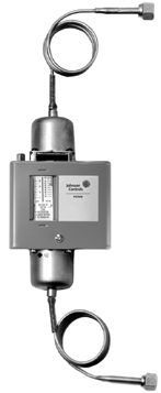
P74EA-8 Differential Pressure Control
1. Maximum continuous pressure to low pressure bellows – 180 psig (1,241 kPa)
Technical Specifications
Electrical Ratings
| Motor Ratings | 120 V | 208 V | 240 V | 277 V |
| P74AA, P74BA – 1 Phase | ||||
| AC Full Load A | 20.0 | 18.7 | 17.0 | — |
| AC Locked Rotor A | 120.0 | 112.2 | 102.0 | — |
| AC Non-Inductive A | 22.0 | 22.0 | 22.0 | — |
| Pilot Duty | 125 VA, 120 to 600 VAC; 57.5 VA, 120 to 300 VDC | |||
| P74EA | ||||
| AC Full Load A | 16.0 | 9.2 | 8.0 | — |
| AC Locked Rotor A | 96.0 | 55.2 | 48.0 | — |
| AC Non-Inductive A | 16.0 | 16.0 | 16.0 | 16.0 |
| Pilot Duty | 125 VA, 120 to 600 VAC | |||
| P74FA | ||||
| AC Full Load A | 6.0 | 3.4 | 3.0 | — |
| AC Locked Rotor A | 36.0 | 20.4 | 18.0 | — |
| AC Non-Inductive A | 10.0 | 10.0 | 10.0 | 10.0 |
| Pilot Duty | 125 VA, 120 to 277 VAC | |||
| P74JA | ||||
| 1 A; 24 VAC Class 2; 50/60 Hz | ||||
Electromechanical Lube Oil and Differential Pressure Controls Code No. LIT-1927280
 P128 and P145 Series Lube Oil Pressure Controls
![]()
![]()
![]()
Description
The P128 and P145 Series Controls provide dependable low pressure lube oil cut-out for pressure lubricated refrigeration compressors. The P128 Series offer adjustable range settings.
The P128 and P145 controls feature a 1/4 in. external flare pressure connection which may be used with a refrigerant hose or cap tube such as SEC99 UltraCap.
Refer to the P28 and P128 Series Lube Oil Control with Built-in Time Delay Relay Product Bulletin (LIT-125420) for important product application information.
Features
• ambient compensated time delay relay
• trip-free manual reset
• industry standard
• P128 is fully adjustable throughout its range
• P145 is factory set to compressor manufacturer’s specifications
Applications
Use these controls for lube oil cutout on hermetic and semi-hermetic compressors used in commercial air-conditioning and commercial and industrial refrigeration systems.
Selection Chart
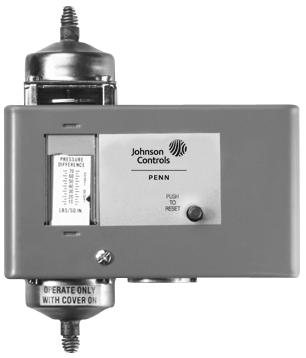
P128AA Lube Oil Pressure Control
Technical Specifications
Pressure controls P128 and P145 are designed to be used with SEC99 UltraCap. Product specifications for P128 are the same as P28 model. Refer to P28 Series Lube Oil Pressure Cutout Control (With Time Delay) (LIT-1927185). Product specifications for P145 are the same as P45 model. Refer to P45 Series Lube Oil Pressure Cutout Control (With Time Delay) (LIT-1927185).
Also note the selection chart below.
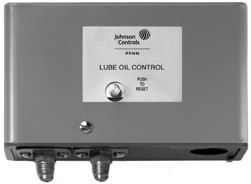
P145NCA Lube Oil Pressure Control
Accessories
Some controls are supplied less mounting brackets. If brackets are required, order kit number BKT38A-600, which contains
five 271-51 angle mounting brackets with screws; or BKT38A-601 which contains one mounting bracket with screws.
Repair Information
If the P128 and the P145 Series Lube Oil Pressure Control fails to operate within its specifications, replace the unit. For a replacement control, contact the nearest Johnson Controls® representative.
- Replacement for P28AA-1*. Replaces Ranco® P30-3701.
- Replacement for P28AA-2*. Replaces Ranco P30-3601.
- Replacement for P28AA-17*. Replaces Ranco P30-3801.
- Replacement for P45NCA-12*. (Copeland Model) Replaces Ranco P30-5826.
- Replacement for P45NCA-82*. (Carlyle Model).
- Copeland model with alarm circuit
- Carlyle model with alarm circuit
* SEC99 UltraCap Hose must be ordered separately.
Electromechanical Lube Oil and Differential Pressure Controls Code No. LIT-1900115
 P12 Series Differential Pressure Controls
![]()
![]()
![]()
Description
The P12 Series Differential Pressure Controls are suitable for use with oil and/or
non-corrosive refrigerants. The switch is actuated by a difference in pressure between the two sensing elements. The control is factory-set to open the switch (COM to 1) at a differential pressure of 18 psi (124 kPa) and close the switch (COM to 1) at a differential pressure of 12 psi (83 kPa). The control is not field-adjustable.
This control may be connected to a P28 Lube Oil Control, with time delay, to give complete monitoring of lubrication on two refrigeration compressors driven by one motor.
Refer to the P12 Series Differential Pressure Control Product Bulletin (LIT-997452) for important product application information.
Repair Information
If the P12 Series Differential Pressure Control fails to operate within its specifications, replace the unit. For a replacement control, contact the nearest Johnson Controls® representative.
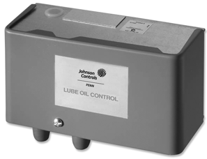
P12AA
Differential Pressure Control
Selection Chart
Electronic Lube Oil and Differential Pressure Controls Code No. LIT-1900355
 P545 Series Electronic Lube Oil Control
![]()
![]()
![]()
Description
The P545 Series Electronic Lube Oil Control is designed for use on refrigeration compressors equipped with an oil pump that accepts a single-point differential pressure switch. The P400 switch continuously monitors net lube oil pressure and the P545 control locks out the compressor if lube oil pressure falls below the manufacturer’s recommended net pressure for longer than the recommended lube oil time delay. Front-mount LEDs indicate the status of the lubrication system, and a user-selectable, minimum-off time delay can be set to minimize compressor short cycling.
A Johnson Controls/PENN® R310AD Current Sensing Switch, sold separately, may be used to disable the P545 control lockout circuit during abnormal compressor shutdowns.
Refer to the P545 Series Electronic Lube Oil Control Product Bulletin (LIT-12011012) for important product application information.
Features
• single-pole, double-throw (SPDT) relay contacts for liquid line solenoid and alarm applications allow liquid line solenoid to be closed if the P545 control shuts off the compressor due to low oil pressure and provides alarm indication, including circuits that use neon lights
Selection Charts
P545 Series Electronic Lube Oil Control
• relay contact output for compressor provides reliable, long-lasting operation
• built-in test circuit verifies proper control operation quickly, without additional tools or equipment
• improved noise immunity exceeds immunity requirements of UL 991 for transient overvoltage: IEC 61000-4-3 for radiated Radio Frequency (RF) and IEC 61000-4-6 for RF-induced conducted disturbances
• jumper-selectable anti-short cycle time delays provide for a wide range of
anti-short cycle strategies that meet most equipment requirements— the anti-short cycle delay feature may allow for the elimination of an external short-cycle timer
• user-friendly display panel displays the status of the compressor lubrication system continuously
• backwards compatibility allows easy replacement of existing electronic lube oil controls
Repair Information
If the P545 Series Electronic Lube Oil Control fails to operate within its specifications, replace the unit. For a replacement control, contact the nearest Johnson Controls® representative.
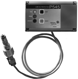
P545 Control with P400 Switch
| Product Code Number | Lube Oil Delay (Seconds) | P400 Switch | Wiring Harness | Fits Compressors Manufactured by |
| P545NCB-22C1 | 120 | P400AD-2 | WHA-P400-100 | Copeland |
| P545NCB-25C1 | 90 | P400BD-1 | WHA-P400-125 | Bitzer |
| P545NCB-82C1 | 120 | P400AD-1 | WHA-P400-100 | Carlyle |
1. Switch and wiring harness included
Control and Sensor/Switch Compatibility
| Test | P345 or P445 Control
with P400 Switch |
P545 Control and
P400 Switch |
| Wiring Harness1 | WHA-P400-xxx | WHA-P400-xxx |
| Test Switch | Does not function2 | Immediate |
- WHA-P400-xxx is the two-wire harness supplied with the P545 control and the P400 switch.
- When the P445 Control is wired to a P400 Switch, the Test button may operate when first powered up; however, after a couple minutes of operation, the Test Switch function no longer works. All other control functions operate normally.
Electronic Lube Oil and Differential Pressure Controls
P545 Series Electronic Lube Oil Control (Continued)
![]()
![]()
![]()
![]()
Accessories
P400 Single-Point Differential Lube Oil Pressure Switch
1. Wiring harness included
Wiring Harnesses and Other Accessories
1. Contact Carlyle Compressor Co. at 1-800-462-2759 to order Sensor Block Gasket 06DA680063.
Technical Specifications
| P545NCB Electronic Lube Oil Control | |
| Power Requirements | 120 or 240 VAC, 50/60 Hz +10%, -15%; power consumption: 3 VA |
| Open Point (Differential Pressure) | P545NCB-22/P400AD-2: 12.75 ± 0.75 psi (87.9 ± 5.17 kPa)
P545NCB-25/P400BD-1: 10 ± 1.5 psi (68.9 ± 10.3 kPa) P545NCB-82 P400AD-1: 7 ± 1.0 psi (48.2 ± 6.9 kPa) |
| Lube Oil Time Delay (Factory Settings) | P545NCB-22: 120 ± 15 seconds
P545NCB-25: 90 ± 12 seconds P545NCB-82: 120 ± 15 seconds |
| Anti-Short Cycle Timer | Four selectable positions: 0, 35, 65, and 100 seconds (nominal times) |
| Type of Refrigerant | Non-corrosive refrigerants only |
| Electrical Connections | Control: Screw type terminals on a barrier terminal strip
Sensor: Snap-connect at sensor end, three-pin plug at control end |
| Maximum Electrical Rating | Isolated relay output to compressor contactor (M-1 and M-2) Pilot duty 375 VA at 120 VAC, 750 VA at 240 VAC |
| Alarm Circuit (Relay) | NOA contact: Pilot duty 125 VA at 120/240 VAC; 60 W tungsten at 120/240 VAC NCA contact: Pilot duty 125 VA at 120 VAC, 250 VA at 240 VAC |
| Backplate Material
Case and Cover Material |
0.062 in. (1 mm) cold rolled steel High impact thermoplastic |
| Ambient Operating Conditions | -40 to 131°F (-40 to 5°C) |
| Ambient Storage Conditions | -40 to 185°F (-40 to 85°C) |
| Approximate Shipping Weight | 1.80 lb (0.82 kg) |
| Agency Listings | UL Listed, File SA516, CCN SDFY
UL Listed for Canada, File SA516, CCN SDFY7 |
Electronic Lube Oil and Differential Pressure Controls Code No. LIT-1900111
 CST29A Adaptor Block for Carlyle® Compressors
![]()
![]()
![]()
Description
The Johnson Controls/PENN® CST29A Adaptor Block is designed for use on Carlyle® compressors (models O6CC, O6D, and O6E) equipped with an oil pump. The adaptor block allows for the installation of the P400 single point differential pressure switch for use with the P545NCB-82 electronic lube oil control.
Refer to the CST29A Adapter Block for Carlyle Compressors Product Bulletin (LIT-125730) for important product application information.
Selection Chart
| Product Code Number | Description |
| CST29A-600C | Adaptor Block for Carlyle Compressor Series O6CC, O6D, and O6E;
Includes Allen-head bolts. |
Features
• simple installation— provides easy conversion of electromechanical lube oil control system to electronic equivalent
• designed specifically for Carlyle applications— applies to Carlyle compressor models O6CC, O6D, and O6E
Repair Information
If the CST29A Adaptor Block for Carlyle® Compressors fails to operate within its specifications, replace the unit. For a replacement adaptor, contact the nearest Johnson Controls® representative.
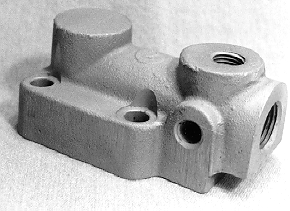
CST29A Adaptor Block
- Order this part from a Carlyle distributor. For information on the nearest Carlyle distributor, contact Carlyle at 1-800-462-2759.
Pressure Sensors and Accessories Code No. LIT-1927395
 Replacement Timing Relays for P28 and P29 Lube Oil Controls
![]()
![]()
![]()
Selection Chart
Pressure Sensors and Accessories Code No. LIT-1927275
 P100 Series Encapsulated Pressure Switches
![]()
![]()
![]()
Description
P100 Series switches are encapsulated, nonadjustable, single-pole, single-throw (SPST), direct-mount switches for use with non-corrosive refrigerants. The switches are available with automatic reset in both open low and open high configurations and manual reset with open high action.
Refer to the P100 Series Encapsulated Pressure Controls Product Bulletin (LIT-121485) for important product application information.
Features
• compact size and light weight allow for direct mounting
• trip-free manual reset (manual reset models); contacts cannot be overridden by continued depression of the reset button
• use with all non-corrosive refrigerants
• encapsulated switch, dust tight
• 1/4 in. Internal flare fitting with built-in Schrader type depressor is standard
• electrical connections are made to 48 in. leads
Applications
• low limit, high limit, and fan cycling control in commercial refrigeration
• ice machines
• food service equipment
Repair Information
If the P100 Series Encapsulated Pressure Switches fails to operate within its specifications, replace the unit. For a replacement switch, contact the nearest Johnson Controls® representative.
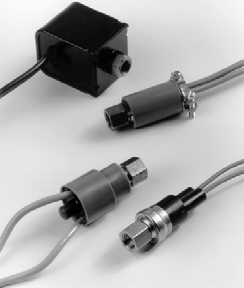
P100 Series Encapsulated Pressure Switch
Technical Specifications
Standard Duty Electrical Contact Ratings
| Switch Action-Model
Numbers |
SPST-P100AA, AC, AG, AJ, CA, CC, CG, CJ, DA, and
DC |
SPST-P100AP, CP | ||
| Motor Ratings | 120V | 240V | 120V | 240V |
| AC Full Load Ampere | 5.8 | 2.9 | 6.0 | 6.0 |
| AC Locked Rotor Ampere | 34.8 | 15.0 | 36.0 | 36.0 |
| Non-Inductive Ampere | – | – | – | – |
| Inductive Ampere | – | – | – | – |
| Pilot Duty | 375 VA | 375 VA | ||
Heavy Duty Electrical Contact Ratings
| Switch Action-Model
Numbers |
SPST-P100AE and CE | SPDT-P100EE | ||||||
| Motor Ratings | 120V | 240V | 120V | 240V | ||||
| Contact Type | N.O. | N.C. | N.O. | N.C. | N.O. | N.C. | N.O. | N.C. |
| AC Full Load Ampere | 13.0 | 13.0 | 10.0 | 10.0 | 5.8 | 13.0 | 2.9 | 10.0 |
| AC Locked Rotor Ampere | 65.0 | 60.0 | 45.0 | 45.0 | 34.8 | 60.0 | 17.4 | 45.0 |
| Non-Inductive Ampere | 13.0 | 25.0 | 10.0 | 25.0 | 10.0 | 25.0 | 5.0 | 25.0 |
| Inductive Ampere | 15.0 | 15.0 | 15.0 | 15.0 | 15.0 | 15.0 | 15.0 | 15.0 |
| Pilot Duty | 278 VA | 125 VA | 278 VA | 125 VA | 278 VA | 125 VA | 278 VA | 125 VA |
Pressure Sensors and Accessories
Johnson Controls, Inc. shall not be liable for damages resulting from misapplication or misuse of its products. © 2015 Johnson Controls, Inc.
R-116
Selection Chart (Part 1 of 3)
![]()
![]()
![]()
P100 Series Encapsulated Pressure Switches (Continued)
The performance specifications are nominal and conform to acceptable industry standards. For applications at conditions beyond these specifications, consult the local Johnson Controls office.
![]()
| Product Code Number | Switch Action | Setpoints – psig (kPa) | Replaces: | |||||||||
| Opens | Closes | Ranco | Robert- shaw | Saginomiya | Danfoss | Klixon | Supco | Wilspec | International
Refrigeration Products |
Gemline | ||
| P100AC-1C2 | Open on Pressure Drop | 5 (34) | 20 (138) | MPL-7001 | – | ACB-2UA318W | – | PS80-K2-F0305- 020-005 | SLP0520 | HR201A020005D | SLP0520 | – |
| P100AP-354C | 5 (34) | 30 (207) | – | 3100-002 | – | – | – | SLP0530 | – | – | – | |
| P100AP-15C | 10 (69) | 25 (172) | HR00011A1R702 | 3100-050 | ACB-2UA97W | 061F7523 | PS80-K2-F0307- 025-005 | SLP1025 | HR201A025010D | SLP1025 | – | |
| P100AP-201C | 10 (69) | 32 (221) | MPL-7011 | 3100-050 | ACB-2UA101 | – | – | SLP1032 | – | SLP1032 | – | |
| P100AC-2C2 | 15 (103) | 30 (207) | MPL-7002 | – | – | – | – | – | – | – | – | |
| P100AP-356C | 20 (138) | 45 (310) | – | 3100-003 | ACB-2UA40W | – | – | SLP2045 | – | – | – | |
| P100AP-12C | 25 (172) | 50 (345) | – | – | ACB-2UA143 | – | PS80-K2-F0316- 050-005 | SLP2550 | HR201A050025D | SLP2550 | – | |
| P100AP-9C | 25 (172) | 80 (551) | MPL-7003 | 3101-003 | – | – | PS80-K2-F0325- 080-005 | SLP2580 | HR201A080025D | SLP2580 | – | |
| P100AP-105C | 30 (207) | 60 (413) | – | 3100-004 | ACB-2UA94 | – | – | – | – | SLP3560 | – | |
| P100AP-2C | 35 (241) | 60 (414) | MPL-7004 | 3100-004 | – | – | – | SLP3560 | – | SLP3560 | – | |
| P100AP-10C | 40 (276) | 60 (413) | HR00011A1R704 | – | – | – | – | – | – | – | – | |
| P100AP-357C | 40 (276) | 80 (551) | – | 3100-052 | ACB-2UA354W | – | PS80-K2-F0326- 080-005 | SLP4080 | HR201A080040D | SLP4080 | – | |
| P100AP-361C | 50 (345) | 90 (620) | – | – | – | – | PS80-KS-F0328- 090-005 | SLP5090 | HR201A090050D | SLP5090 | – | |
| P100AP-358C | 75 (517) | 100 (689) | – | – | ACB-2UA441W | – | – | – | – | SLP75100 | – | |
| P100AP-351C1 | 75 (517) | 120 (827) | – | – | – | – | – | SFC75120 | – | – | – | |
| P100AP-352C1 | 110 (758) | 170
(1,171) |
– | – | – | – | – | SFC110170 | – | – | – | |
| P100AP-353C1 | 126 (868) | 264
(1,819) |
– | – | – | – | – | SFC125265 | – | – | – | |
| P100AP-3C1 | 150
(1,034) |
225
(1,551) |
MPF-7008 | – | ACB-2UA685W | – | – | SFC150225 | – | – | – | |
| P100AP-359C1 | 165
(1,137) |
215
(1,481) |
– | 3100-215 | ACB-2UA48W | – | – | – | – | – | – | |
| P100AP-4C1 | 170
(1,172) |
250
(1,724) |
– | – | ACB-2UA631W | – | – | SFC170250 | – | – | – | |
| P100AP-362C1 | 195
(1,344) |
240
(1,654) |
– | 3100-080 | – | – | – | – | – | – | – | |
| P100AP-200C1 | 195
(1,344) |
275
(1,895) |
– | – | – | – | – | – | – | – | – | |
Pressure Sensors and Accessories
Johnson Controls, Inc. shall not be liable for damages resulting from misapplication or misuse of its products. © 2015 Johnson Controls, Inc.
R-117
Selection Chart (Part 2 of 3)
![]()
![]()
![]()
P100 Series Encapsulated Pressure Switches (Continued)
The performance specifications are nominal and conform to acceptable industry standards. For applications at conditions beyond these specifications, consult the local Johnson Controls office.
![]()
| Product Code Number | Switch Action | Setpoints – psig (kPa) | Replaces: | |||||||||
| Opens | Closes | Ranco | Robert- shaw | Saginomiya | Danfoss | Klixon | Supco | Wilspec | International Refrigeration Products | Gemline | ||
| P100AP-354C1 | Open on Pressure Drop | 210
(1,447) |
275
(1,895) |
– | – | ACB-2UA319W | – | – | SFC210275 | – | SFC210275 | – |
| P100EE-79C | 300
(2,068) |
370
(2,551) |
– | – | – | – | – | – | – | – | – | |
| P100AP-332C1 | 300
(2,068) |
400
(2,758) |
MPF7010 | – | ACB-2UA627W | 061F7514 | – | SFC300400 | – | – | – | |
| P100CP-157C | Open on Pressure Rise | 225
(1,550) |
150
(1,034) |
– | – | – | – | – | – | – | – | – |
| P100CP-158C | 250
(1,723) |
150
(1,034) |
– | – | – | – | PS80-K1-0336- 250-150 | SHP250150 | HR202A250150D | SHP250150 | – | |
| P100CP-159C | 270
(1,860) |
200
(1,378) |
– | – | – | – | – | – | – | – | – | |
| P100CC-9C2 | 275
(1,896) |
175
(1,207) |
– | 3100-112 | ACB-2UB724W | – | – | – | – | – | – | |
| P100CP-91C | 300
(2,067) |
200
(1,378) |
– | – | ACB-2UB723W | – | PS80-K1-0341- 300-200 | – | HR202A300200D | SHP300200 | – | |
| P100CP-166C | 325
(2,239) |
225
(1,550) |
– | – | – | 061F6080 | PS80-K1-0346- 320-230 | SHP325225 | HR202A325230D | – | – | |
| P100CP-140C | 350
(2,412) |
245
(1,688) |
– | 3100-150 | ACB-2UB273W | 061F3212 | PS80-K1-0348- 350-245 | – | HR202A350245D | SHP350250 | – | |
| P100CP-160C | 375
(2,584) |
275
(1,895) |
– | – | ACB-2UB191 | 061F7509 | – | – | – | SHP375265 | – | |
| P100CP-161C | 400
(2,756) |
200
(1,378) |
– | 3100-152 | – | – | PS80-K1-0357- 400-200 | SHP400200 | HR202A400200D | SHP400200 | – | |
| P100CP-162C | 400
(2,756) |
280
(1,929) |
– | – | – | – | PS80-K1-0358- 400-280 | SHP400280 | HR202A400280D | SHP400280 | – | |
| P100EE-78C | 400
(2,756) |
300
(2,068) |
– | – | – | – | – | – | – | – | – | |
| P100CP-1C | 400
(2,758) |
300
(2,068) |
MPH-7107 | 3100-151 | ACB-2UB35 | 061FS14 | PS80-K1-0359- 400-300 | SHP400300 | HR202A400300D | SHP400300 | PC 151 | |
| P100CP-156C | 410
(2,825) |
290
(1,998) |
– | – | – | – | – | – | – | – | – | |
| P100CP-163C | 425
(2,928) |
300
(2,067) |
– | – | – | – | PS80-K1-0360- 425-300 | SHP425300 | HR202A425300D | SHP425300 | – | |
| P100CP-2C | 425
(2,930) |
325
(2,241) |
MPH-7108 | 3100-100 | ACB-2UB282W | – | – | SHP425325 | – | – | PC 100 | |
| P100CP-164C | 450
(3,101) |
250
(1,723) |
– | – | – | – | PS80-K1-0363- 450-250 | SHP450250 | HR202A450250D | SHP450250 | – | |
| P100CP-38C | 500
(3,447) |
325
(2,241) |
– | – | – | – | – | – | – | – | – | |
| P100CP-165C | 600
(4,134) |
475
(3,273) |
HR00011B1R704 | – | – | 061F7517 | – | SHP600475 | – | – | – | |
| P100CP-85C | 665
(4,585) |
565
(3,895) |
– | – | – | – | – | SHP665565 | – | – | – | |
Johnson Controls, Inc. shall not be liable for damages resulting from misapplication or misuse of its products. © 2015 Johnson Controls, Inc.
R-118
Selection Chart (Part 3 of 3)
![]()
![]()
![]()
P100 Series Encapsulated Pressure Switches (Continued)
The performance specifications are nominal and conform to acceptable industry standards. For applications at conditions beyond these specifications, consult the local Johnson Controls office.
![]()
| Product Code Number | Switch Action | Setpoints – psig (kPa) | Replaces: | |||||||||
| Opens | Closes | Ranco | Robert- shaw | Saginomiya | Danfoss | Klixon | Supco | Wilspec | International Refrigeration Products | Gemline | ||
| P100DA-35C | 350
(2,413) |
Lockout Manual Reset | – | – | ACBPC45M | – | – | – | – | – | – | |
| P100DC-3C3 | 375
(2,586) |
Lockout Manual Reset | – | – | – | – | – | – | – | SMR375 | – | |
| P100DA-1C | 410
(2,827) |
Lockout Manual Reset | – | 3100-103 | ACBPB115M | – | 29PSL012-24 | SMR410 | HM202A410000D | SMR410 | PC 103 | |
| P100DA-100C | Open on | 415
(2,859) |
Lockout Manual Reset | – | 3100-103 | – | – | 29PSL004-1 | – | HM202A415000D | SMR410 | – |
| Pressure | ||||||||||||
| P100DA-101C | 440
(3,032) |
Lockout Manual Reset | – | – | – | – | – | SMR440 | – | SMR440 | – | |
| Rise | ||||||||||||
| P100DA-2C | 475
(3,275) |
Lockout Manual Reset | – | 3100-106 | – | – | – | – | HM202A475000D | – | – | |
| P100DA-86C | 575
(3,964) |
Lockout Manual Reset | – | – | – | – | – | SMR575 | – | – | – | |
| P100DA-81C | 630
(4,343) |
Lockout Manual
Reset |
– | – | – | – | – | SMR630 | – | – | – | |
-
- Models are designed for condenser fan cycling.
Pressure Sensors and Accessories
-
- Includes conduit clamp for 3/8 in. flexible metal conduit.
- Includes conduit box with opening for 1/2 in. conduit connector.
Pressure Sensors and Accessories Code No. LIT-1900405
 P499 Series Electronic Pressure Transducers
![]()
![]()
![]()
Description
The P499 Series Electronic Pressure Transducers are compact, economical, rugged, direct-mount pressure transducers designed for use in commercial refrigeration and air conditioning applications.
These transducers produce an analog signal based on the sensed pressure.
The P499 Series transducers feature environmentally protected electronics with stainless steel construction. The digitally compensated P499 transducers are highly accurate over a broad temperature range, resisting the effects of wide ambient temperature swings, high humidity, condensation, and icing.
The pressure port is machined from a solid piece of 17-4PH stainless steel. No O-rings, organic materials, or welds are exposed to the pressure media, allowing for a leak-proof, all-metal, sealed pressure system.
The P499 Series transducers operate with any corrosive or non-corrosive pressure medium that is compatible with 17-4PH
stainless steel, including water, condensate, carbon dioxide, glycol, most refrigerants (including ammonia), and many other compatible fluids and gases.
The P499 Series provides transducers in a variety of pressure ranges, covering most common refrigeration and air conditioning applications.
Features
• single-piece machined 17-4PH stainless steel pressure port provides a durable assembly that eliminates refrigerant loss due to O-ring or weld failures; resists damage due to physical shock, vibration, and pressure pulsations; enables use with non-corrosive or corrosive pressure media that is compatible with 17-4PH stainless steel.
• environmentally protected electronics withstand the effects of adverse conditions associated with typical HVAC/R applications, including freeze/thaw applications on suction lines.
• reliable, repeatable performance and long operating life minimizes service and replacement costs.
• many available pressure ranges provide a single line of transducers for all refrigeration and air conditioning application needs.
• 1% total error band provides high-accuracy performance.
• slender body design facilitates use of deep-socket wrenches for ease of installation; requires zero turning radius.
• CE and UL agency listings allow for global applications.

P499 Electronic Pressure Transducers; Style 47 Fitting Shown on the Left and Style 49 Fitting Shown on the Right
Refer to the P449 Series Electronic Pressure Transducer Product/Technical Bulletin (LIT-12011190) for important product application information.
Repair Information
If the P499 Series Electronic Pressure Transducer fails to operate within its specifications, replace the unit. For a replacement transducer, contact the nearest Johnson Controls® representative.
Accessories
P499 transducers require wire harnesses for all models that do not have an integral cable.
Wire Harnesses with Packard Electrical Connectors
| Product Code Number1 | Length |
| WHA-PKD3-200C | 6-1/2 ft (2.0 m) |
| WHA-PKD3-400C | 13 ft (4.0 m) |
| WHA-PKD3-600C | 19-5/8 ft (6.0 m) |
1. Wire harnesses for P399 transducers and P499 transducers are interchangeable.
Selection Chart
0.5 to 4.5 VDC Ratiometric P499 Transducer Models with Packard Electrical Connections, psis
| Product Code Number | Pressure Connection | Pressure Range1 | Individual or Kit2 | |
| Minimum Pressure (Pmin) | Maximum Pressure (Pmax) | |||
| P499RAPS100C | 1/8 in. 27 NPT External Thread (Style 49) | -10 psis (-0.7 bar)
[20 in. Hg] |
100 psis (6.9 bar) | Individual |
| P499RAPS100K | Kit | |||
| P499RAPS102C | 0 psis (0 bar) | 200 psis (13.8 bar) | Individual | |
| P499RAPS102K | Kit | |||
| P499RCPS100C | 1/4 in. SAE 45 Flare Internal Thread
(7/16-20 UNF) with Depressor (Style 47) |
-10 psis (-0.7 bar)
[20 in. Hg] |
100 psis (6.9 bar) | Individual |
| P499RCPS100K | Kit | |||
| P499RAPS102C | 0 psis (0 bar) | 200 psis (13.8 bar) | Individual | |
| P499RAPS102K | Kit | |||
- Transducer sealed and rated for IP67 harsh environments.
- The Individual pack comes with a transducer only – you must order the wire harness separately. The Kit is packaged with a transducer, 6-1/2 ft (2 m) wire harness, and technical documentation.
Pressure Sensors and Accessories
P499 Series Electronic Pressure Transducers (Continued)
![]()
![]()
![]()
![]()
0.5 to 4.5 VDC Ratiometric P499 Transducer Models with Integral 2 m (6-1/2 ft) Shielded Cable, psis
| Product Code Number | Pressure Connection | Pressure Range1 | |
| Minimum Pressure (Pmin) | Maximum Pressure (Pmax) | ||
| P499RCSS101C | 1/4 in. SAE 45 Flare Internal Thread
(7/16-20 UNF) with Depressor (Style 47) |
0 psis (0 bar) | 100 psis (6.9 bar) |
1. Transducer sealed and rated for IP67 harsh environments.
0.5 to 4.5 VDC Ratiometric P499 Transducer Models with Packard Electrical Connections, psi
| Product Code Number | Pressure Connection | Pressure Range | Individual or Kit1 | |
| Minimum Pressure (Pmin) | Maximum Pressure (Pmax) | |||
| P499RAP-101C | 1/8 in. 27 NPT External Thread (Style 49) | 0 psi (0 bar) | 100 psi (6.9 bar) | Individual |
| P499RAP-101K | Kit | |||
| P499RAP-102C | 0 psi (0 bar) | 200 psi (13.8 bar) | Individual | |
| P499RAP-105C | 0 psi (0 bar) | 500 psi (34.5 bar) | Individual | |
| P499RAP-105K | Kit | |||
| P499RAP-107C | 0 psi (0 bar) | 750 psi (51.7 bar) | Individual | |
| P499RAP-107K | Kit | |||
| P499RCP-101C | 1/4 in. SAE 45 Flare Internal Thread (7/16-20 UNF) with Depressor (Style 47) | 0 psi (0 bar) | 100 psi (6.9 bar) | Individual |
| P499RCP-101K | Kit | |||
| P499RCP-105C | 0 psi (0 bar) | 500 psi (34.5 bar) | Individual | |
| P499RCP-105K | Kit | |||
| P499RCP-107C | 0 psi (0 bar) | 750 psi (51.7 bar) | Individual | |
| P499RCP-107K | Kit | |||
1. The Individual pack comes with a transducer only – you must order the wire harness separately. The Kit is packaged with a transducer, 6-1/2 ft (2 m) wire harness, and technical documentation.
0 to 10 VDC P499 Transducer Models with Packard Electrical Connections, psi
| Product Code
Number |
Pressure Connection | Pressure Range | Individual or Kit1 | |
| Minimum Pressure
(Pmin) |
Maximum Pressure
(Pmax) |
|||
| P499VAP-101C | 1/8 in. 27 NPT External Thread (Style 49) | 0 psi (0 bar) | 100 psi (6.9 bar) | Individual |
| P499VAP-101K | Kit | |||
| P499VAP-105C | 0 psi (0 bar) | 500 psi (34.5 bar) | Individual | |
| P499VAP-105K | Kit | |||
| P499VAP-107C | 0 psi (0 bar) | 750 psi (51.7 bar) | Individual | |
| P499VAP-107K | Kit | |||
| P499VCP-101C | 1/4 in. SAE 45 Flare Internal Thread (7/16-20 UNF) with Depressor (Style 47) | 0 psi (0 bar) | 100 psi (6.9 bar) | Individual |
| P499VCP-101K | Kit | |||
| P499VCP-105C | 0 psi (0 bar) | 500 psi (34.5 bar) | Individual | |
| P499VCP-105K | Kit | |||
| P499VCP-107C | 0 psi (0 bar) | 750 psi (51.7 bar) | Individual | |
| P499VCP-107K | Kit | |||
1. The Individual pack comes with a transducer only, you must order the wire harness separately. The Kit is packaged with a transducer, 6-1/2 ft (2 m) wire harness, and technical documentation.
4 to 20 mA P499 Transducer Models with Packard Electrical Connections, psi (Part 1 of 2)
| Product Code
Number |
Pressure Connection | Pressure Range | Individual or Kit1 | |
| Minimum Pressure (Pmin) | Maximum Pressure (Pmax) | |||
| P499AAP-101C | 1/8 in. 27 NPT External Thread (Style 49) | 0 psi
(0 bar) |
100 psi
(6.9 bar) |
Individual |
| P499AAP-101K | Kit | |||
| P499AAP-105C | 0 psi
(0 bar) |
500 psi
(34.5 bar) |
Individual | |
| P499AAP-105K | Kit | |||
| P499AAP-107C | 0 psi
(0 bar) |
750 psi
(51.7 bar) |
Individual | |
| P499AAP-107K | Kit | |||
Pressure Sensors and Accessories
P499 Series Electronic Pressure Transducers (Continued)
![]()
![]()
![]()
![]()
4 to 20 mA P499 Transducer Models with Packard Electrical Connections, psi (Part 2 of 2)
| Product Code
Number |
Pressure Connection | Pressure Range | Individual or Kit1 | |
| Minimum Pressure (Pmin) | Maximum Pressure (Pmax) | |||
| P499ACP-101C | 1/4 in. SAE 45 Flare Internal Thread
(7/16-20 UNF) with Depressor (Style 47) |
0 psi
(0 bar) |
100 psi
(6.9 bar) |
Individual |
| P499ACP-101K | Kit | |||
| P499ACP-105C | 0 psi
(0 bar) |
500 psi
(34.5 bar) |
Individual | |
| P499ACP-105K | Kit | |||
| P499ACP-107C | 0 psi
(0 bar) |
750 psi
(51.7 bar) |
Individual | |
| P499ACP-107K | Kit | |||
- The Individual pack comes with a transducer only, you must order the wire harness separately. The Kit is packaged with a transducer, 6-1/2 ft (2 m) wire harness, and technical documentation.
Technical Specifications
| P499 Series Electronic Pressure Transducers | ||
| Pressure Ranges | -10 to 100 psis, 0 to 100 psi, 0 to 200 psi, 0 to 500 psi, 0 to 750 psi | |
| Maximum Working Pressure | 2x Pressure Range; short duration; infrequent, abnormal condition | |
| Burst Pressure | 5x Pressure Range | |
| Vacuum | 30 microns (0.03 mm Hg); short term | |
| Media Compatibility | All media compatible with 17-4PH stainless steel, including ammonia | |
| Output Signal | 0.5 to 4.5 VDC, 0 to 10 VDC, or 4 to 20 mA | |
| Supply Voltage | 0.5 to 4.5 VDC Ratiometric Output | 5.0 ±0.25 VDC, Safety Extra-Low Voltage (SELV) or Class 2 |
| 4 to 20 mA Output | 9 to 30 VDC, SELV or Class 2 | |
| 0 to 10 VDC Output | 12 to 30 VDC, SELV or Class 2 | |
| Direct-Mount Pressure Connections | 1/8 in. 27 NPT External Thread (Style 49),
1/4 in. SAE 45 Flare Internal Thread (7/16-20 UNF) with Depressor (Style 47) |
|
| Temperature and Humidity | Storage | -40 to 257F (-40 to 125C) |
| Operating | -40 to 185F (-40 to 85C) | |
| Compensated Range | -4 to 185F (-20 to 85C) | |
| Humidity | 0 to 100% RH | |
| Linearity | ±0.25% Full Span best fit straight line | |
| Accuracy | ±1% Full Span (maximum) over compensated temperature range | |
| Materials | Pressure Port | 17-4PH stainless steel construction |
| Packard Connector | 40% glass-filled Polyetherimide (PEI) | |
| Vibration | 20G, 20 to 200 Hz | |
| Shock | 200G/11 ms | |
| Compliance
|
United States | UL Listed, File E29374, CCN NKPZ
UL Recognized for Use in Class I, Division 2 Hazardous Locations, File E322274 |
| Canada | UL Listed, File E29374, CCN NKPZ7
UL Recognized for Use in Class I, Division 2 Hazardous Locations, File E322274 |
|
| Europe | CE Mark – Johnson Controls, Inc., declares that this product is in compliance with the essential
requirements and other relevant provisions of the EMC Directive 2004/108/EC. |
|
| Australia/
New Zealand |
C-Tick Mark, Emissions Compliant | |
Pressure Sensors and Accessories Code No. LIT-1900005
 R310A Series Current Sensing Switch
![]()
![]()
![]()
Description
The R310A Series Current Sensing Switch detects alternating current (AC) flow in a single circuit without being connected to that circuit. It may be used in any application where current detection is required.
The R310A replaces the R10A used with Johnson Controls/PENN® time delay oil failure cutout controls such as the P28, P45, and P445. These applications incorporate internal line breaking overload protection, where lockout due to overload cycling is unacceptable or undesirable. The
R310A switch is not intended to detect breakage of belts.
The R310A is molded in a high dielectric material, which permits mounting inside a starter or contactor.
Refer to the R310A Series Current Sensing Switch Product Bulletin (LIT-121536) for important product application information.
Features
• small size allows mounting in small enclosure
• solid-state switching contains no moving parts to fail
• low 0.5 ampere activation allows monitoring of most small equipment circuit loads
• high 200 ampere monitoring capacity allows monitoring of heavy duty equipment
• large 0.70 in. (18 mm) diameter sensor hole accepts large diameter wire sizes and multiple coilings of smaller diameter wire sizes
Applications
The R310A Current Sensing Switch is designed to sense alternating current in a conductor that passes through its opening. The R310A sensor closes an electronic switch if the alternating current in the conductor exceeds 0.5 amperes. Thus, the R310A switch may be used for several purposes:
• switch a pilot circuit
• energize a run signal on a device such as a fan, motor, or pump
• monitor motors and electrical loads for proper operation
• monitor on/off status of process motors
The R310A Series Current Sensing Switch is available in two models. The R310AD-1 switch is for use in low-voltage applications, such as with the P445 Electronic Lube Oil Control. The R310AE-2 switch is for use in high-voltage applications, such as with the P28 and
P45 Electromechanical Lube Oil Controls.
The R310A switch avoids nuisance lockouts by sensing the lack of current flow to the motor. Regardless of the reason for motor shutdown, the lube oil control time delay circuit is de-energized when the current flow in the motor supply line drops below 0.5 amperes.
In a typical application, the lube oil control does not lock out when the control circuit shuts off the compressor. However, if the compressor overheats and the internal thermal overload circuits open,
the compressor shuts itself down, which causes the oil pressure to drop. This drop in oil pressure will energize the lube oil control heater (P28, P45) or timer (P445), causing a
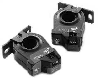
R310A Series Current Sensing Switch
nuisance lockout. In this situation, the
R310 switch senses the lack of current to the motor, and is used to de-energize the time delay heater (P28, P45) or electronic timer (P445) before a nuisance lockout occurs.
Repair Information
If the R310A Series Current Sensing Switch fails to operate within its specifications, replace the unit. For a replacement switch, contact the nearest Johnson Controls® representative.
Selection Chart Technical Specifications
| R310A Series Current Sensing Switch | ||
| Switch Action | SPST, normally open | |
| Current Sensing Range | R310AD-1C | 0.5 to 200 Amperes |
| R310AE-2C | 0.75 to 200 Amperes | |
| Switch Threshold | R310AD-1C | 0.5 Amperes |
| R310AE-2C | 0.75 Amperes | |
| Sensor Supply Voltage | Induced from monitored conductor, isolation 600 VAC RMS | |
| Switching Capacity (General Purpose) | R310AD-1C | 0.1A at 30 VAC/DC |
| R310AE-2C | 0.5 at 250 VAC/DC | |
| Output Polarity | Non-polarity sensitive output | |
| Enclosure | NEMA 1 | |
| Ambient Operating Conditions | 5 to 140°F (-15 to 60°C);
0 to 95% RH, noncondensing |
|
| Ambient Storage Conditions | -40 to 158°F (-40 to 70°C);
0 to 95% RH |
|
| Dimensions (H x W x D) | 2.34 x 1.85 x 0.875 in.
(59 x 46 x 22 mm) |
|
| Sensor Hole Size | 7/10 in. (17 mm) Diameter | |
| Agency Listings | UL Guide NRNT cUL Guide NRNT7 | |
Pressure Sensors and Accessories Code No. LIT-1900108
 Universal Mounting Brackets
![]()
![]()
![]()
Description
The 271-51 is the universal mounting bracket used with many Johnson Controls/PENN® products. BKT38A-601R contains one mounting bracket with screws. BKT38A-600R contains five 271-51 angle mounting brackets with screws.
Selection Chart
| Product Code | Description |
| 271-51 | Universal Mounting Bracket |
| BKT38A-600R | Five Universal Mounting Brackets with ten screws |
271-51
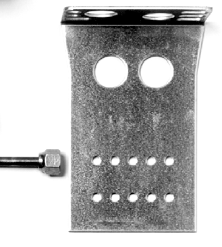
Universal Mounting Bracket
Pressure Sensors and Accessories Code No. LIT-1900131
 SEC99A UltraCap Armored Capillary
![]()
![]()
![]()
Description
The SEC99A UltraCap Armored Capillary is designed for use as a pressure connection in refrigeration and air conditioning applications. This small-orifice capillary minimizes pressure pulsation, and the brass armor sleeve improves resistance to abrasion caused by vibration. The copper capillary inside the armored sleeve allows no effusion of refrigerant to the environment.
Selection Chart
UltraCap is designed for use with 1/4 in. SAE external flare fitting connectors, such as those found on the Johnson Controls/PENN® lines of pressure-actuated controls. Integral Schrader valve depressors are available.
UltraCap Armored Capillary is compatible with all common non-corrosive refrigerants. The UltraCap capillary is available in a variety of lengths, and in models with two straight fittings or with one straight fitting and one 90° elbow fitting.
Repair Information
If the SEC99A UltraCap Armored Capillary fails to operate within its specifications, replace the unit. For a replacement capillary, contact the nearest Johnson Controls® representative.
SEC99AB and SEC99AA UltraCap Armored Capillaries
Refrigerant Sensors/Monitors Code No. LIT-1900954
 RLD-H10PRO Refrigerant Leak Detector
![]()
![]()
![]()
Description
The RLD-H10PRO is a professional-grade leak detector for use by refrigeration and air conditioning technicians. This detector senses all CFC, HCFC, and HFC refrigerants and blends, such as R12, R22, R134a, R404a, R410a, R502, and R507 among others. The RLD-H10PRO is self-powered with a rechargeable battery and provides both manual and automatic compensation for background levels of refrigerant. A full line of accessories and maintenance kits are also available, including replacement sensors, tuneup kits, probe extensions, battery chargers, and leak vial bottles.
Refer to the RLD-H10PRO Refrigerant Leak Detector Product Bulletin (LIT-12012073) for important product application information.
Features
- positive ion emission heated diode sensor provides the most sensitivity available today, while still detecting all halogenated refrigerant gases
Selection Chart
| Product Code | Description |
| RLD-H10PRO-1 | Refrigerant leak detector and
charger |
Accessories
• rechargeable battery with low and full charge LEDs enhances portability—no external power required
• high quality air pump supplies constant airflow to the sensor so it responds quickly to leaks; also helps the sensor recover quickly after exposure to a refrigerant so the leak can be verified
• switchable adjustment for manual or automatic balance allows users to choose their preferred method of compensation for background refrigerant levels
• visual and audible signal facilitates sensing in noisy equipment rooms with 360° visibility and a piercing tone. Frequency of noise and light indicates the magnitude of the leak.
• headset jack allows users to hear the leak detector response in noisy environments
• external calibration source and calibration indicators indicate when the sensor is working properly and serves as a reference point to judge leak size
Technical Specifications
| RLD-H10PRO Refrigerant Leak Detector | ||
| Power Requirements | 12 VDC internal battery, or 100 to 240 VAC input/18 V output wall adaptor
(included) (RLD-H10-101). |
|
| Sensing Element Type | Positive ion emission heated diode | |
| Approximate Sensitivity1 | Stationary | 0.006 oz./yr |
| Moving (Per SAE J2791) | 0.1 oz./yr | |
| Automatic Background Adjustment | Mode selection for automatic or manual background zeroing Manual background zeroing provides the best sensitivity. | |
| Leak Alarm | Audible alarm (through internal beeper or stereo headphone jack), visible red LED | |
| Response Time | Approximately 1 second | |
| Warmup Time | Approximately 2 minutes | |
| Probe Length | Approximately 4-1/2 ft (1.4 m) | |
| Ambient Operating Conditions | 32 to 104°F (0 to 40°C); 5-90% RH, noncondensing | |
| Ambient Storage Conditions | 14 to 140°F (-10 to 60°C); 5-90% RH, noncondensing | |
| Case | Rugged high-density polyethylene | |
| Dimensions (H x W x D) | 5-2/5 x 10-1/2 x 8-3/10 in. (137 x 267 x 211 mm) | |
| Compliance | Europe: CE Mark Johnson Controls, Inc. declares that this product is in compliance with the essential requirements and other relevant provisions of the EMC Directive 2004/108/EC. | |
| Shipping Weight | 5.1 lb (2.3 kg) | |
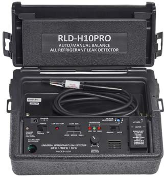
RLD-H10PRO Refrigerant Leak Detector
Repair Information
If the RLD-H10PRO Refrigerant Leak Detector fails to operate within its specifications, contact Johnson Controls® application engineering at (414) 524-5535.
![]()
-
- Sensitivity for R12, R22, R134a, R410a, R404a, and R507 when unit is set to small leak setting, manual mode.
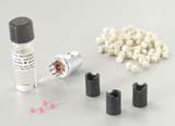
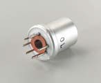


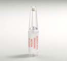
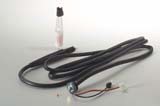
Refrigerant Sensors/Monitors Code No. LIT-1900116
 RLD Refrigerant Leak Detector Accessories and Replacement Parts
![]()
![]()
![]()
Description
These parts are used on the RLD-H10G-1 and on the RLD-H10PRO-1.
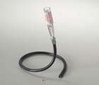 Selection Chart
Liquid Level and Flow Controls Code No. LIT-1922325
 F59 Series Sump Pump Switch
![]()
![]()
![]()
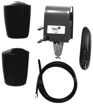
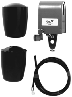 Description
The F59 Series Controls are designed to start an electric motor on liquid level rise and stop the motor on liquid level drop. The control cuts in when upper weight is submerged approximately halfway, and cuts out when lower weight is approximately half-exposed.
Each switch includes 36 in. cable and two weights.
Refer to the F59 Series Liquid Level Switch for Sump Operations Product Bulletin
(LIT-125215) for important product application information.
Type F59A, F59H
F59A-2 Sump Pump Switch F59H-1 Sump Pump Switch
![]()
Line
Line
M2
M1
Action on Rise in Liquid Level
f59.eps
F59 Series Action Diagram
Features
F59D-5 is equipped with a power cord and a piggyback style plug. The external prongs plug into the wall outlet, and the sump pump cord plugs into the internal end of the plug.
Applications
Use for On/Off control of sump pumps.
Technical Specifications
Electrical Ratings
Selection Charts
Replacement Parts
| Volts | Horsepower |
| F59A-1 | |
| 120 VAC | 1 hp |
| 240 VAC | 1 hp |
| 32 VDC | 1/4 hp |
| F59A-2 | |
| 120 VAC | 1 hp |
| 240 VAC | 1 hp |
| 32 VDC | 1/4 hp |
| F59D-5 | |
| 120 VAC | 1/2 hp |
| F59H-1 | |
| 120 VAC | 1 hp |
| 240 VAC | 1 hp |
| 32 VDC | 1/4 hp |
Liquid Level and Flow Controls Code No. LIT-1900948
 F261 Series Fluid Flow Switches
![]()
![]()
![]()
Description
The F261 Series Flow Switches respond to fluid flow in lines carrying water, ethylene glycol, or other nonhazardous fluids. These models also work in applications with swimming pool water and lubricating oils.
F261 Series Standard Flow Switches use a variety of paddle sizes to respond to fluid flow rates in applications with pipe sizes greater than 1 inch trade size.
Refer to the F261 Series Fluid Flow Switches Product Bulletin (LIT-12011987) for important product application information.
Selection Chart
F261 Series Standard Model Flow Switches
Features
- Type 3R (NEMA) or Type 4 (NEMA) enclosure allows use in indoor or outdoor applications.
- Viton® diaphragms allow use in fluid lines carrying chlorinated water, treated water, or other nonhazardous fluids.
- low-flow operation on low-flow models actuates switch with less than
1.0 GPM (3.8 L/min) flow for water applications or 9.0 GPM (34.1 L/min) flow for steam applications.
- maximum fluid pressure of 290 psig (20 bar) permits use in a wide range of pressure flow conditions.
Repair Information
If the F261 Series Flow Switch fails to operate within its specifications, replace the unit. For a replacement F261 Series Flow Switch, contact the nearest Johnson Controls® representative.
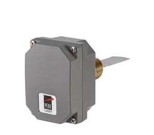
F261 Flow Switch
F261 Series Low-Flow Model Flow Switches
Replacement Paddle Parts
| Product Code Number | Description |
| KIT21A-600 | Stainless steel three-piece paddle (3 in., 2 in., and 1 in. segments) |
| KIT21A-601 | Stainless steel 6 in. paddle |
| PLT52A-600R | Stainless steel three-piece paddle (3 in., 2 in., and 1 in. segments) and Stainless steel 6 in. paddle |
Technical Specifications
F261xxH Series Standard Controls Electrical Ratings
| Volts, 50/60 Hz | UL60730/UL1059 | EN60730 | ||||
| 24 | 120 | 208 | 240 | 24 | 230 | |
| Horsepower | – | 1 | 1 | 1 | – | – |
| Full Load Amperes | – | 16 | 10 | 10 | – | 8 |
| Locked Rotor Amperes | – | 96 | 60 | 60 | – | 48 |
| Resistive Amperes | 16 | 16 | 10 | 10 | 16 | 16 |
| Pilot Duty VA | 125 | 720 | 720 | 720 | 77 | 720 |
Liquid Level and Flow Controls
F261 Series Fluid Flow Switches (Continued)
![]()
![]()
![]()
![]()
UL Conformity Declaration Information
| Information | Description |
| Purpose of Control | F261 Fluid Flow Switch |
| Construction of Control | Electronic independently mounted control |
| Number of Cycles | 100,000 cycles |
| Method of Mounting Control | Mounting to sensed media vessel/orientation |
| Type 1 or Type 2 Action | Type 1.C (Microinterruption) |
| External Pollution Situation | Pollution degree 4 |
| Internal Pollution Situation | Pollution degree 2 |
| Rated Impulse Voltage | 4,000 VAC |
| Ball Pressure Temperature | Enclosure: 266°F (130°C)
Switch Component: 252°F (122°C) |
| Control Adjustment Instruction | – |
| Field Wiring Rating | Wire/Cord Temperature Ratings:
140°F (60°C) only permitted when ambient air and media are less than 113°F (45°C) 167°F (75°C) only permitted when ambient air and media are less than 140°F (60°C) 194°F (90°C) only permitted when ambient air is less than 140°F (60°C) and media is less than 167°F (75°C) 302°F (150°C) permitted when ambient air is less than 140°F (60°C) and media is less than 249°F (121°C) |
| Vessel Pressure | F261 Fluid Flow Switch: 290 psi (20 Bar) |
| F261 Series Fluid Flow Switches | |
| Switch | Single-Pole, Double-Throw (SPDT) |
| Enclosure | UL: Type 3R or Type 4
CE: IP43 (IP23 with drain hole plug removed) or IP67 |
| Wiring Connections | Three color-coded screw terminals and one ground terminal |
| Conduit Connection | One 7/8 in. (22 mm) hole for 1/2 in. trade size (or PG16) conduit |
| Pipe Connector | Standard: 1 in. 11-1/2 NPT Threads |
| Maximum Fluid Pressure | 290 psi (20 bar) |
| Minimum Fluid Temperature1 | -20°F (-29°C) |
| Maximum Fluid Temperature2 | 250°F (121°C) |
| Ambient Conditions | -40 to 140°F (-40 to 60°C) |
| Compliance
|
North America: cULus Listed; UL 60730, File E6688; FCC Compliant to CFR47, Part 15, Subpart B, Class B
Industry Canada (IC) Compliant to Canadian ICES-003, Class B limits |
| Europe: CE Mark – Johnson Controls, Inc. declares that this product is in compliance with the essential requirements and
other relevant provisions of the EMC Directive and the Low Voltage Directive. |
|
| Australia/New Zealand Mark: RCM Compliant | |
- Ensure that the low liquid temperature combined with the low ambient temperature does not lead to the freezing the liquid inside the body (or bellows, where appropriate). Please observe the liquid freezing point.
- At higher ambient temperatures, the maximum allowed liquid temperature becomes lower. The temperature of the electrical switch inside should not exceed 158°F (70°C).
Liquid Level and Flow Controls Code No. LIT-1900949
 F262 Airflow Switch
![]()
![]()
![]()
Description
The F262 Airflow Switch detects airflow or the absence of airflow by responding only to the velocity of air movement within a duct. The single-pole, double-throw (SPDT) control can be wired to open one circuit and close a second circuit for either signaling or interlock purposes.
Airflow failure during the normal operation of air handling systems may cause overheating, coil icing, or other conditions that may be detrimental to the equipment.
Refer to the F262 Airflow Switch Product Bulletin (LIT-12011988) for important product application information.
Application
The F262 switch detects airflow or the absence of airflow by responding only to the velocity of air movement within a duct. The SPDT control can be wired to open one circuit and close a second circuit for either signaling or interlock purposes.
Failure of airflow during the normal operation of air handling systems may cause overheating, coil icing, and other conditions that may be detrimental to the equipment.
Typical applications include:
- Make-up air systems
- Air cooling or heating processes
- Exhaust systems
The control has a Type 3R (NEMA) enclosure with an integral mounting plate. A mounting plate gasket is supplied with each switch.
Features
- Type 3R (NEMA) Polycarbonate enclosure allows use in indoor applications and provides dust protection and is approved for use in a plenum according to NEC
- dependable dust-protected SPDT snap-acting PENN switch detects the presence or absence of airflow
- large wiring space makes wiring convenient and easily accessible
- easily accessible range adjustment screw allows easy field adjustment
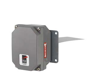
F262 Airflow Control
Repair Information
If the F262 Airflow Switch fails to operate within its specifications, replace the unit. For a replacement F262 Airflow Switch, contact the nearest Johnson Controls® representative.
Selection Charts
F262 Airflow Switch
Replacement Paddle Kits for F262 Switch
| Product Code Number | Description |
| PLT112-1R | 2-1/8 in. wide x 6-7/8 in. long (54 mm x 175 mm) paddle |
| PLT112-2R | 3-1/8 in. wide x 6-7/8 in. long (79 mm x 175 mm) paddle |
Technical Specifications
F262 Switch Electrical Ratings
| Volts 50/60 Hz | UL60730 | EN60730 | ||||
| 24 | 120 | 208 | 240 | 24 | 230 | |
| Horsepower | – | 1 | 1 | 1 | – | – |
| Full Load Amperes | – | 16 | 10 | 10 | – | 8 |
| Locked Rotor Amperes | – | 96 | 60 | 60 | – | 48 |
| Resistive Amperes | 16 | 16 | 10 | 10 | 16 | 16 |
| Plot Duty VA | 125 | 720 | 720 | 720 | 125 | 720 |
Liquid Level and Flow Controls
F262 Airflow Switch (Continued)
![]()
![]()
![]()
![]()
| F262 Series Airflow Switch | |
| Switch | SPDT |
| Enclosure | UL: Type 3R CE: IP43 |
| Wiring Connections | Three color-coded screw terminals and one ground terminal |
| Conduit Connection | One 7/8 in. (22 mm) hole for 1/2 in. trade size (or PG16) conduit |
| Paddle Material | 0.006 in. (0.15 mm) stainless spring steel |
| Maximum Air Velocity | 2,000 FPM (10.16 m/s) |
| Maximum Duct Air Temperature | 176°F (80°C) |
| Ambient Conditions | 32 to 104°F (0 to 40°C) |
| Compliance
|
North America: cULus Listed; UL 60730, File E6688; FCC Compliant to CFR47, Part 15, Subpart B, Class B
Industry Canada (IC) Compliant to Canadian ICES-003, Class B limits |
| Europe: CE Mark – Johnson Controls, Inc. declares that this product is in compliance with the essential
requirements and other relevant provisions of the EMC Directive and the Low Voltage Directive. |
|
| Australia/New Zealand Mark: RCM Compliant | |
Liquid Level and Flow Controls Code No. LIT-1900950
 F263 Series Liquid Level Float Switches
![]()
![]()
![]()
Description
The F263 Series Liquid Level Float Switches are designed to maintain a liquid level in indoor or outdoor closed tanks that hold water or other nonhazardous liquids. When the liquid level in the tank rises above or falls below the required level, the single-pole, double-throw (SPDT) switch closes one circuit and opens a second circuit.
Refer to the F263 Series Liquid Level Float Switches Product Bulletin (LIT-12011989) for important product application information.
Application
Use F263 Series Float Switches in closed tanks where a liquid level is to be maintained. A change in the liquid level opens or closes an electrical circuit.
Use F263MAP switches on indoor or outdoor tanks that hold water or other nonhazardous liquids at temperatures greater than the liquid’s freezing point and between -20°F
(-29°C) and 212°F (100°C). The maximum allowable liquid pressure is 150 psig (1,035 kpa).
Use F263MAC switches on indoor or outdoor tanks that hold water or other nonhazardous liquids at temperatures greater than the liquid’s freezing point and between -20°F
(-29°C) and 250°F (121°C). The maximum allowable liquid pressure is 100 psig
(690 kpa).
Note: Do not use these float switches with liquids that are lighter than water.
Features
- Viton® diaphragm allows use in fluid lines carrying chlorinated water, treated water, or other nonhazardous liquids.
- single-pole, double-throw switch provides control where liquid levels rise and fall
- sturdy Type 4 (NEMA) enclosure allows for use in indoor or outdoor applications; inhibits the formation of moisture in low temperature applications.
- solid polycarbonate float
(F263MAP models) provides greater resistance to corrosion
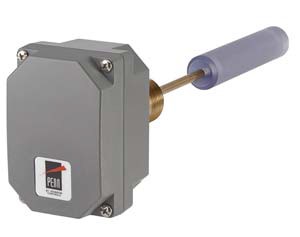
F263 Liquid Level Float Switch
Repair Information
If the F263 Series Liquid Level Float Switch fails to operate within its specifications, replace the unit. For a replacement
F263 Switch, contact the nearest Johnson Controls® representative.
Selection Chart
Technical Specifications
F263 Switch Electrical Ratings
| Volts 50/60 Hz | UL60730 | EN60730 | ||||
| 24 | 120 | 208 | 240 | 24 | 230 | |
| Horsepower | – | 1 | 1 | 1 | – | – |
| Full Load Amperes | – | 16 | 10 | 10 | – | 8 |
| Locked Rotor Amperes | – | 96 | 60 | 60 | – | 48 |
| Resistive Amperes | 16 | 16 | 10 | 10 | 16 | 16 |
| Plot Duty VA | 125 | 720 | 720 | 720 | 125 | 720 |
Liquid Level and Flow Controls
F263 Series Liquid Level Float Switches (Continued)
![]()
![]()
![]()
![]()
| F263 Series Liquid Level Float Switches | |
| Switch | SPDT |
| Enclosure | UL: Type 4 (NEMA) CE: IP67 |
| Wiring Connections | Three color-coded screw terminals and one ground terminal |
| Conduit Connection | One 7/8 in. (22 mm) hole for 1/2 in. trade size (or PG16) conduit |
| Pipe Connector | 1 in. 11-1/2 NPT threads |
| Minimum Tank Diameter | 9 in. (229 mm) |
| Maximum Liquid Pressure | 100 psig (690 kPa) for copper float
150 psig (1,035 kPa) for polycarbonate float |
| Liquid Temperature Range | Minimum: -20°F (-29°C) or liquid freezing point
Maximum: 212°F (100°C) polycarbonate, 250°F (121°C) copper |
| Ambient Conditions | Minimum: -40°F (-40°C) Maximum: 140°F (60°C) |
| Compliance
|
North America: cULus Listed; UL 60730, File E6688; FCC Compliant to CFR47, Part 15, Subpart B, Class B
Industry Canada (IC) Compliant to Canadian ICES-003, Class B limits |
| Europe: CE Mark – Johnson Controls, Inc. declares that this product is in compliance with the essential
requirements and other relevant provisions of the EMC Directive and the Low Voltage Directive. |
|
| Australia/New Zealand Mark: RCM Compliant | |
Liquid Level and Flow Controls Code No. LIT-1922525
 F61 and F62 Series Replacement Paddles
![]()
![]()
![]()
Selection Chart
Liquid Level and Flow Controls Code No. LIT-1922350
 F92 Series Air Volume Controls for Shallow Wells
![]()
![]()
![]()
Description
The F92 Series Air Volume Controls for Shallow Wells control the amount of air in the residential water storage tanks of shallow well water systems. Shallow wells are less than 25 ft. (7.6 m) deep.
F92 Series Controls automatically maintain air volume in the storage tanks of shallow well water systems by allowing room air to enter into the air charging section of the pump when the water level in the tank rises (loss of air volume).
F92 Controls open the air valve on a rise in tank water level to permit charging air into the storage tank with pressures up to
80 psig (552 kPa).
Refer to the F92 Series Air Volume Controls for Shallow Wells Product Bulletin (Part No. 24-7664-2993) for important product application information.
Features
- sturdy Noryl (high performance thermoplastic) body resists mechanical damage and corrosion.
- brass internal operating parts minimize corrosion.
- pressure tested plastic float provides long operating life.
- optional pressure gauge tapping allows mounting of a pressure gauge.
Selection Chart
| Product Code
Number |
Description |
| F92A-4C | Air Volume Control for Shallow Wells, opens on pressure rise, barbed fitting on charger valve |
| F92B-1C | Air Volume Control for Shallow Wells, opens on pressure rise, 1/4-18 PTF SAE short gage tap, 0.016 in. (0.5 mm) valve orifice. Use this model in applications where excessive airflow may reduce water pumping capacity. |
| F92B-2C | Air Volume Control for Shallow Wells, opens on pressure rise, 1/4-18 PTF SAE short gage tap |
Technical Specifications
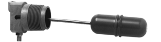
F92 Series Air Volume Control for Shallow Wells
Application
Water storage tanks in residential water systems rely on a volume of air in the tank to provide system pressure, making it important to control the amount of air in the tank:
- Too little air in the tank results in rapid pump cycling — a problem common in shallow well systems (less than 25 ft [7.6 m] deep).
- Too much air in the tank results in air entering the distribution system — a problem common in deep well systems
(more than 25 ft [7.6 m] deep).
Repair Information
If the F92 Series Air Volume Controls for Shallow Wells fails to operate within its specifications, replace the unit. For a replacement F92 Series control, contact the nearest Johnson Controls® representative.
| F92 Series Air Volume Control for Shallow Wells | |
| Body Material | 30% glass-filled Noryl thermoplastic |
| Float Material | Plastic with brass rod |
| Maximum Tank Pressure | 80 psig (552 kPa) |
| Shipping Weight | Individual: 0.25 lb (0.11 kg)
Bulk pack (30): 30.9 lb (4.08 kg) |
| Tank Connector Size | 1-1/4 in. external NPT |
| Air Flow Restrictor Orifice | F92B-1C Model: 0.016 in. (0.5 mm) |
| Snifter Line Connection | Flare fitting for 3/16 in. (5 mm) tubing |
Liquid Level and Flow Controls Code No. LIT-1922355
 F93 Series Air Volume Controls for Deep Wells
![]()
![]()
![]()
Description
The F93 Series Air Volume Controls for Deep Wells control the amount of air in the residential water storage tanks of deep well water systems. Deep wells are more than 25 ft (7.6 m) deep.
F93 Series Controls automatically maintain air volume in the storage tanks of deep well water systems by allowing air to escape from the tank and into the surrounding room when the water level in the tank drops (increase of air volume).
F93 deep well controls open the air valve on a fall in tank water level to bleed excess air from the tank at pressures up to 100 psig (690 kPa).
The F93H has a minimum pressure release valve to avoid lowering tank pressure below 25 psig (172 kPa). Use this model on applications where water may be rapidly drained.
Refer to the F93 Series Air Volume Controls for Deep Wells Product Bulletin (Part No. 24-7664-3000) for important product application information.
Features
- sturdy Noryl (high performance thermoplastic) body resists mechanical damage and corrosion.
- brass internal operating parts minimize corrosion.
- pressure tested plastic float provides long operating life.
- optional pressure gauge tapping allows mounting of a pressure gauge.
- certification for Federal Safe Drinking Water Act (SDWA) meets the US Federal standards of the Reduction of Lead in Drinking Water Act.
Selection Chart
| Product Code
Number |
Description |
| F93A-1C | Air Volume Control for Deep Wells, opens on pressure drop, no gage tap, no pressure release valve |
| F93B-1C | Air Volume Control for Deep Wells, opens on pressure drop, 1/4-18 PTF SAE short gage tap, no pressure release valve |
| F93H-1C | Air Volume Control for Deep Wells, opens on pressure drop, 1/4-18 PTF SAE short gage tap, with
25 psig (172 kPa) minimum air pressure release valve. Use this model in applications where water may be rapidly drawn from the system. |
Technical Specifications
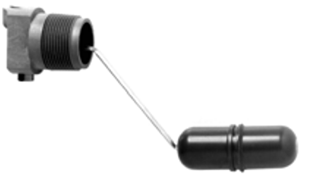
F93 Series Air Volume Control for Deep Wells
Application
Water storage tanks in residential water systems rely on a volume of air in the tank to provide system pressure, making it important to control the amount of air in the tank:
- Too little air in the tank results in rapid pump cycling – a problem common in shallow well systems (less than 7.6 m [25 ft] deep).
- Too much air in the tank results in air entering the distribution system — a problem common in deep well systems
(more than 7.6 m [25 ft] deep).
Repair Information
If the F93 Series Air Volume Controls for Deep Wells fails to operate within its specifications, replace the unit. For a replacement F93 Series control, contact the nearest Johnson Controls® representative.
| F93 Series Air Volume Control for Deep Wells | |
| Body Material | 30% glass-filled Noryl thermoplastic |
| Float Material | Plastic with brass rod |
| Maximum Tank Pressure | 100 psig (690 kPa) |
| Shipping Weight | Individual: 0.25 lb (0.11 kg)
Bulk pack (30): 30.9 lb (4.08 kg) |
| Tank Connector Size | 1-1/4 in. external NPT |
| Compliance | United States Federal Safe Drinking Water Act (SDWA) Compliant,
Underwriters Laboratories Classified in Accordance with NSF/ANSI 372 (File MH59894) |
Motor Speed Controls Code No. LIT-1900595
 P266 Series Single-Phase Condenser Fan Speed Control
![]()
![]()
![]()
Description
The P266 Series Single-Phase Condenser Fan Speed Control is a cost-effective, weather-resistant, durable motor speed control. The P266 Series Controls are designed for approved single-phase, Permanent Split-Capacitor (PSC) motors commonly used in a wide variety of refrigeration and air conditioning condenser fan applications.
The P266 Series Controls are designed to replace the Johnson Controls® P66 Series and P215 Series fan speed controls, providing additional features and flexibility, greater energy efficiency, and longer motor life in a compact, rugged, weather-resistant package.
P266 Series Controls are available for 208 through 575 VAC 50/60 Hz range applications. P266 Series controls have
current ratings from 4 to 12 A, depending on the voltage and model.
Some P266 Series Controls provide optional control of up to three auxiliary (fixed-speed) fans or fan stages. In addition, some models provide two additional high-voltage triacs that allow you to split the source power to the main and auxiliary windings, and connect a
low-speed capacitor to increase efficiency at low-speed operation.
Refer to the P266 Series Single-Phase Condenser Fan Speed Control Product Bulletin (LIT-12011534) for important product application information.
Features
- one or two durable, accurate, stainless steel, remote-mount pressure transducers
- available in 208/240 VAC (8 or 12 A), 380/460 VAC (4 A), or 460/575 VAC (4 A)
- wide, adjustable pressure throttling range
- optional auxiliary fan control
- optional low-speed capacitor mode
- NEMA 3R, (IP54) enclosure with integral metal heat-sink and stand-off mounting feet
Application
The P266 Series Single-Phase Condenser Fan Speed Control, in conjunction with a P266 Series Electronic Pressure Transducer, is a pressure-actuated, digital electronic motor speed control designed for approved
single-phase, PSC motors used in a wide variety of HVAC/R applications.
The P266 Series Fan Speed Control regulates supply voltage to the fan motor in response to the condenser refrigerant pressure and maintains the appropriate fan speed (air movement) through the condenser regardless of the ambient temperature or air delivery variations.
The P266 Series control is housed in a NEMA 3R (IP54) rainproof enclosure for outdoor applications.
The P266 Series control is an energy efficient and effective alternative to On/Off fan-cycling controls, multiple-speed motors, temperature fan-speed controls, modulating air-damper systems, condenser flood-back systems, and other condenser pressure control methods.
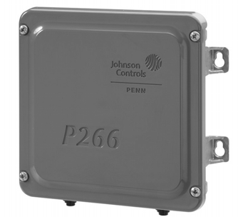
P266 Series Single-Phase Condenser Fan Speed Control
P266 Series Fan Speed Control applications include:
- computer room air conditioning
- commercial refrigeration
- commercial air conditioning
Repair Information
If a P266 Series Single-Phase Condenser Fan Speed Control fails to operate within its specifications, replace the unit. For a replacement P266 Series control, contact the nearest Johnson Controls® representative.
Selection Charts
P266 Series Fan Speed Control Model and Kit Product Code Numbers, Descriptions, and Details (Part 1 of 2)
| Product Code
Number |
Description | Transducer
Model Included in Kit |
Voltage
(VAC) |
Maximum
Output Amperes |
High
VAC Triacs |
Available
Auxiliary Fan Control Circuits1 |
| P266AAA-100C2 | P266 Fan Speed Control (only) | N/A | 208/240 | 8 | 3 | 0 |
| P266ABA-100C2 | P266 Fan Speed Control (only) | N/A | 208/240 | 8 | 3 | 3 |
| P266ACA-100C2 | P266 Fan Speed Control (only) | N/A | 208/240 | 8 | 1 | 0 |
| P266ADA-100C2 | P266 Fan Speed Control (only) | N/A | 208/240 | 8 | 1 | 3 |
| P266BGA-100C2 | P266 Fan Speed Control (only) | N/A | 460/575 | 4 | 2 | 0 |
| P266BHA-100C2 | P266 Fan Speed Control (only) | N/A | 460/575 | 4 | 2 | 3 |
| P266BCA-100C2 | P266 Fan Speed Control (only) | N/A | 460/575 | 4 | 1 | 0 |
| P266BDA-100C2 | P266 Fan Speed Control (only) | N/A | 460/575 | 4 | 1 | 3 |
| P266CHA-100C2 | P266 Fan Speed Control (only) | N/A | 380/460 | 4 | 2 | 3 |
| P266ABA-1K2 | P266 Fan Speed Control with one P266 Pressure Transducer and one 2 m (6.6 ft) cable | P266SNR-1C, 0 to 35 bar
(0 to 508 psig) |
208/240 | 8 | 3 | 3 |
| P266ABA-3K2 | P266 Fan Speed Control with one P266 Pressure Transducer and one 2 m (6.6 ft) cable | P266SNR-2C, 0 to 52 bar
(0 to 754 psig) |
208/240 | 8 | 3 | 3 |
Motor Speed Controls
P266 Series Single-Phase Condenser Fan Speed Control (Continued)
![]()
![]()
![]()
![]()
P266 Series Fan Speed Control Model and Kit Product Code Numbers, Descriptions, and Details (Part 2 of 2)
| Product Code
Number |
Description | Transducer
Model Included in Kit |
Voltage
(VAC) |
Maximum
Output Amperes |
High
VAC Triacs |
Available
Auxiliary Fan Control Circuits1 |
| P266ABA-2K2 | P266 Fan Speed Control with two P266 Pressure Transducers
and two 2 m (6 ft 7-1/5 in.) cables |
P266SNR-1C, 0 to 35 bar
(0 to 508 psi) |
208/240 | 8 | 3 | 3 |
| P266ABA-4K2 | P266 Fan Speed Control with two P266 Pressure Transducers and two 2 m (6 ft 7-1/5 in.) cables | P266SNR-2C, 0 to 52 bar
(0 to 754 psi) |
208/240 | 8 | 3 | 3 |
| P266BHA-1K2 | P266 Fan Speed Control with one P266 Pressure Transducer and one 2 m (6 ft 7-1/5 in.) cable | P266SNR-1C, 0 to 35 bar
(0 to 508 psi) |
460/575 | 4 | 2 | 3 |
| P266BHA-3K2 | P266 Fan Speed Control with one P266 Pressure Transducer and one 2 m (6 ft 7-1/5 in.) cable | P266SNR-2C, 0 to 52 bar
(0 to 754 psi) |
460/575 | 4 | 2 | 3 |
| P266BHA-2K2 | P266 Fan Speed Control with two P266 Pressure Transducers and two 2 m (6 ft 7-1/5 in.) cables | P266SNR-1C, 0 to 35 bar
(0 to 508 psi) |
460/575 | 4 | 2 | 3 |
| P266BHA-4K2 | P266 Fan Speed Control with two P266 Pressure Transducers and two 2 m (6 ft 7-1/5 in.) cables | P266SNR-2C, 0 to 52 bar
(0 to 754 psi) |
460/575 | 4 | 2 | 3 |
| P266EAA-1K2 | P266 Fan Speed Control with Internal Transformer and one
P266 Pressure Transducer and one 2 m (6 ft 7-1/5 in.) cable |
P266SNR-1C, 0 to 35 bar
(0 to 508 psi) |
208/240 | 8 | 3 | 0 |
| P266EAA-3K2 | P266 Fan Speed Control with Internal Transformer and one
P266 Pressure Transducer and one 2 m (6 ft 7-1/5 in.) cable |
P266SNR-2C, 0 to 52 bar
(0 to 754 psi) |
208/240 | 8 | 3 | 0 |
| P266EBA-1K2 | P266 Fan Speed Control with Internal Transformer and one
P266 Pressure Transducer and one 2 m (6 ft 7-1/5 in.) cable |
P266SNR-1C, 0 to 35 bar
(0 to 508 psi) |
208/240 | 8 | 3 | 3 |
| P266EBA-3K2 | P266 Fan Speed Control with Internal Transformer and one
P266 Pressure Transducer and one 2 m (6 ft 7-1/5 in.) cable |
P266SNR-2C, 0 to 52 bar
(0 to 754 psi) |
208/240 | 8 | 3 | 3 |
| P266ECA-1K2 | P266 Fan Speed Control with Internal Transformer and one
P266 Pressure Transducer and one 2 m (6 ft 7-1/5 in.) cable |
P266SNR-1C, 0 to 35 bar
(0 to 508 psi) |
208/240 | 8 | 1 | 0 |
| P266ECA-3K | P266 Fan Speed Control with Internal Transformer and one
P266 Pressure Transducer and one 2 m (6 ft 7-1/5 in.) cable |
P266SNR-2C, 0 to 52 bar
(0 to 754 psi) |
208/240 | 8 | 1 | 0 |
| P266EDA-1K2 | P266 Fan Speed Control with Internal Transformer and one
P266 Pressure Transducer and one 2 m (6 ft 7-1/5 in.) cable |
P266SNR-1C, 0 to 35 bar
(0 to 508 psi) |
208/240 | 8 | 1 | 3 |
| P266EDA-3K2 | P266 Fan Speed Control with Internal Transformer and one
P266 Pressure Transducer and one 2 m (6 ft 7-1/5 in.) cable |
P266SNR-2C, 0 to 52 bar
(0 to 754 psi) |
208/240 | 8 | 1 | 3 |
| P266EEA-1K2 | P266 Fan Speed Control with Internal Transformer and one
P266 Pressure Transducer and one 2 m (6 ft 7-1/5 in.) cable |
P266SNR-1C, 0 to 35 bar
(0 to 508 psi) |
208/240 | 12 | 1 | 0 |
| P266EEA-3K2 | P266 Fan Speed Control with Internal Transformer and one
P266 Pressure Transducer and one 2 m (6 ft 7-1/5 in.) cable |
P266SNR-2C,
0 to 52 bar (0 to 754 psi) |
208/240 | 12 | 1 | 0 |
| P266EFA-1K2 | P266 Fan Speed Control with Internal Transformer and one
P266 Pressure Transducer and one 2 m (6 ft 7-1/5 in.) cable |
P266SNR-1C, 0 to 35 bar
(0 to 508 psi) |
208/240 | 12 | 1 | 3 |
- 24 VAC Class 2 at 1/4 A.
- Factory default settings: Start Voltage is set to 40% of the supply line-voltage. End Voltage is set to 95% of the supply line-voltage. Start Pressure is set to 44% of the P266 Transducer’s total pressure range. End Pressure is set to 51% of the P266 Transducer’s total pressure range.
P266 Series SNR Electronic Pressure Transducers
| Product Code
Number |
Description |
| P266SNR-1C | Electronic Pressure Transducer: 0 to 35 bar (0 to 508 psi) total range with a 1/4 in. SAE Internal Flare connection and a 2 meter
(6 ft 7-1/5 in.) cable. |
| P266SNR-2C | Electronic Pressure Transducer: 0 to 52 bar (0 to 754 psi) total range with a 1/4 in. SAE Internal Flare connection and a 2 meter (6 ft 7-1/5 in.) cable. |
Motor Speed Controls
P266 Series Single-Phase Condenser Fan Speed Control (Continued)
![]()
![]()
![]()
![]()
Technical Specifications
| P266xxx-x Series Single Phase Condenser Fan Speed Controls | |
| Input Supply Power | 208/240 VAC 50/60 Hz, 380/460 VAC 50/60 Hz, or 460/575 VAC 50/60 Hz, depending on model (Refer to the label inside the
P266 Series control housing cover for rated voltage range and model-specific wiring diagram.) |
| Short Circuit Current Rating | Suitable for use on a circuit capable of delivering not more than 5,000 rms symmetrical amperes, 600 Volts maximum when protected by Class H Fuses. |
| Low-Voltage Power Supply | P266A, P266B, and P266C Types: External 24 VAC Class 2, 20 VA Supply Transformer P266E Types: Low-voltage power for P266 control is provided by an onboard transformer.
Note: When auxiliary fan starters are connected to P266E type controls, you must provide an external Safety Extra-Low Voltage (SELV) AC supply to power the fan starters. |
| Ambient Operating Conditions | Temperature: -40 to 60C (-40 to 140F)
Humidity: Up to 95% RH noncondensing; maximum dew point 29C (85F) |
| Ambient Shipping and Storage Conditions | Temperature: -40 to 85C (-40 to 185F)
Humidity: Up to 95% RH noncondensing; maximum dew point 29C (85F) |
| Low-Voltage Connections | 1/4 in. Quick-Connect terminals, 30 m (100 ft) maximum wiring runs |
| Input Transducer | P266SNR-x Pressure Transducer: 5 VDC for 0.5 to 4.5 VDC ratiometric analog signal |
| Enclosure Type | NEMA 3R, IP54 |
| Case Construction | Aluminum die casting |
| Cover Construction | UV Stabilized Polycarbonate |
| Dimensions (HxWxD) | 159 x 177 x 70 mm (6-1/4 x 7 x 2-3/4 in.) |
| Weight | Heaviest model weight: 1.0 kg (2.2 lb) Approximate shipping weight: 1.2 kg (2.6 lb) |
| Compliance
|
North America: cULus, File E244421; FCC Compliant to CFR47, Part 15, Subpart B, Class A Industry Canada (IC) Compliant to Canadian ICES-003, Class A limits |
| Europe: CE Mark – Johnson Controls, Inc., declares that this product is in compliance with the essential requirements and
other relevant provisions of the EMC Directive 2004/108/EC and the Low Voltage Directive 2006/95/EC. |
|
| Australia: C-Tick Compliant (N1813) | |
Motor Speed Controls Code No. LIT-1900622
 P66/S66 Series Controls to P266 Series Controls Replacement Guide
![]()
![]()
![]()
P66/S66 to P266 Series Controls Cross-Reference (Part 1 of 4)
P66/S66 to P266 Series Controls Cross-Reference (Part 2 of 4)
| Product
Code Number |
Operating
Range (psig) |
ETR
(psig) |
Start
Voltage (%) |
Replacement
Control1 (see notes) |
Transducer
Sold Separately (see notes) |
| P66AAB-1 | 190/250 | 60 | 10 | P266ACA-100C2
P266BCA-100C3 |
P266SNR-1C4 |
| P66AAB-2 | 190/250 | 60 | 10 | P266ACA-100C2
P266BCA-100C3 |
P266SNR-1C4 |
| P66AAB-3 | 180/240 | 60 | 16 | P266ACA-100C2
P266BCA-100C3 |
P266SNR-1C4 |
| P66AAB-4 | 135/165 | 30 | 10 | P266ACA-100C2
P266BCA-100C3 |
P266SNR-1C4 |
| P66AAB-5 | 90/120 | 30 | 16 | P266ACA-100C2
P266BCA-100C3 |
P266SNR-1C4 |
| P66AAB-6 | 170/230 | 60 | 16 | P266ACA-100C2
P266BCA-100C3 |
P266SNR-1C4 |
| P66AAB-7 | 85/115 | 30 | 16 | P266ACA-100C2
P266BCA-100C3 |
P266SNR-1C4 |
| P66AAB-8 | 190/250 | 60 | 16 | P266ACA-100C2
P266BCA-100C3 |
P266SNR-1C4 |
| P66AAB-9 | 170/230 | 60 | 40 | P266ACA-100C2
P266BCA-100C3 |
P266SNR-1C4 |
| P66AAB-10 | 190/250 | 60 | 16 | P266ACA-100C2
P266BCA-100C3 |
P266SNR-1C4 |
| P66AAB-11 | 140/200 | 60 | 16 | P266ACA-100C2
P266BCA-100C3 |
P266SNR-1C4 |
| P66AAB-12 | 220/280 | 60 | 16 | P266ACA-100C2
P266BCA-100C3 |
P266SNR-1C4 |
| P66AAB-13 | 60/90 | 30 | 16 | P266ACA-100C2
P266BCA-100C3 |
P266SNR-1C4 |
| P66AAB-14 | 220/280 | 60 | 40 | P266ACA-100C2
P266BCA-100C3 |
P266SNR-1C4 |
| P66AAB-15 | 190/250 | 60 | 40 | P266ACA-100C2
P266BCA-100C3 |
P266SNR-1C4 |
| P66AAB-16 | 140/170 | 30 | 40 | P266ACA-100C2
P266BCA-100C3 |
P266SNR-1C4 |
| P66AAB-17 | 160/190 | 30 | 40 | P266ACA-100C2
P266BCA-100C3 |
P266SNR-1C4 |
| P66AAB-18 | 180/240 | 60 | 10 | P266ACA-100C2
P266BCA-100C3 |
P266SNR-1C4 |
| P66AAB-19 | 115/145 | 30 | 40 | P266ACA-100C2
P266BCA-100C3 |
P266SNR-1C4 |
| P66AAB-20 | 220/280 | 60 | 16 | P266ACA-100C2
P266BCA-100C3 |
P266SNR-1C4 |
| P66AAB-21 | 220/280 | 60 | 16 | P266ACA-100C2
P266BCA-100C3 |
P266SNR-1C4 |
| P66AAB-22 | 140/170 | 30 | 40 | P266ACA-100C2
P266BCA-100C3 |
P266SNR-1C4 |
| P66AAB-23 | 160/190 | 30 | 40 | P266ACA-100C2
P266BCA-100C3 |
P266SNR-1C4 |
| P66AAB-24 | 160/190 | 30 | 10 | P266ACA-100C2
P266BCA-100C3 |
P266SNR-1C4 |
| Product
Code Number |
Operating
Range (psig) |
ETR
(psig) |
Start
Voltage (%) |
Replacement
Control1 (see notes) |
Transducer
Sold Separately (see notes) |
| P66AAB-25 | 180/240 | 60 | 10 | P266ACA-100C2 P266BCA-100C3 | P266SNR-1C4 |
| P66AAB-26 | 220/280 | 60 | 40 | P266ACA-100C2
P266BCA-100C3 |
P266SNR-1C4 |
| P66AAB-27 | 85/115 | 30 | 40 | P266ACA-100C2
P266BCA-100C3 |
P266SNR-1C4 |
| P66AAB-28 | 135/165 | 30 | 10 | P266ACA-100C2
P266BCA-100C3 |
P266SNR-1C4 |
| P66AAB-29 | 190/250 | 60 | 10 | P266ACA-100C2
P266BCA-100C3 |
P266SNR-1C4 |
| P66AAB-30 | 170/230 | 60 | 16 | P266ACA-100C2
P266BCA-100C3 |
P266SNR-1C4 |
| P66AAB-31 | 115/145 | 30 | 40 | P266ACA-100C2
P266BCA-100C3 |
P266SNR-1C4 |
| P66AAB-32 | 140/200 | 60 | 40 | P266ACA-100C2
P266BCA-100C3 |
P266SNR-1C4 |
| P66AAB-33 | 115/215 | 60 | 40 | P266ACA-100C2
P266BCA-100C3 |
P266SNR-1C4 |
| P66AAB-34 | 320/410 | 90 | 40 | P266ACA-100C2
P266BCA-100C3 |
P266SNR-2C4 |
| P66AAB-35 | 230/320 | 90 | 40 | P266ACA-100C2
P266BCA-100C3 |
P266SNR-1C4 |
| P66AAB-36 | 190/250 | 60 | 10 | P266ACA-100C2
P266BCA-100C3 |
P266SNR-1C4 |
| P66AAB-37 | 320/410 | 90 | 10 | P266ACA-100C2
P266BCA-100C3 |
P266SNR-2C4 |
| P66AAB-38 | 360/450 | 90 | 40 | P266ACA-100C2
P266BCA-100C3 |
P266SNR-2C4 |
| P66AAD-1 | 160/220 | 60 | 25 | P266ACA-100C2
P266BCA-100C3 |
P266SNR-1C4 |
| P66AAD-2 | 190/250 | 60 | 10 | P266ACA-100C2
P266BCA-100C3 |
P266SNR-1C4 |
| P66AAD-3 | 190/250 | 60 | 10 | P266ACA-100C2
P266BCA-100C3 |
P266SNR-1C4 |
| P66AAD-4 | 180/240 | 60 | 10 | P266ACA-100C2
P266BCA-100C3 |
P266SNR-1C4 |
| P66AAD-5 | 160/190 | 30 | 10 | P266ACA-100C2
P266BCA-100C3 |
P266SNR-1C4 |
| P66ABB-20 | 220/280 | 60 | 16 | P266ACA-100C2
P266BCA-100C3 |
P266SNR-1C4 |
| P66ABB-21 | 220/280 | 60 | 16 | P266ACA-100C2
P266BCA-100C3 |
P266SNR-1C4 |
| P66ABB-22 | 140/170 | 30 | 40 | P266ACA-100C2
P266BCA-100C3 |
P266SNR-1C4 |
| P66ABB-23 | 160/190 | 30 | 40 | P266ACA-100C2
P266BCA-100C3 |
P266SNR-1C4 |
| P66ABB-24 | 190/250 | 60 | 16 | P266ACA-100C2
P266BCA-100C3 |
P266SNR-1C4 |
Motor Speed Controls
![]() P66/S66 Series Controls to P266 Series Controls Replacement Guide (Continued)
P66/S66 Series Controls to P266 Series Controls Replacement Guide (Continued)
![]()
![]()
![]()
P66/S66 to P266 Series Controls Cross-Reference (Part 3 of 4)
| Product
Code Number |
Operating
Range (psig) |
ETR
(psig) |
Start
Voltage (%) |
Replacement
Control1 (see notes) |
Transducer
Sold Separately (see notes) |
| P66ABB-25 | 190/250 | 60 | 16 | P266ACA-100C2 P266BCA-100C3 | P266SNR-1C4 |
| P66ABB-26 | 170/230 | 60 | 40 | P266ACA-100C2
P266BCA-100C3 |
P266SNR-1C4 |
| P66ABB-27 | 190/250 | 60 | 40 | P266ACA-100C2
P266BCA-100C3 |
P266SNR-1C4 |
| P66ABB-28 | 320/410 | 60 | 16 | P266ACA-100C2
P266BCA-100C3 |
P266SNR-2C4 |
| P66BAB-1 | 190/250 | 60 | 10 | P266ACA-100C2
P266BCA-100C3 |
P266SNR-1C5 |
| P66BAB-2 | 190/250 | 60 | 10 | P266ACA-100C2
P266BCA-100C3 |
P266SNR-1C5 |
| P66BAB-3 | 170/230 | 60 | 16 | P266ACA-100C2
P266BCA-100C3 |
P266SNR-1C5 |
| P66BAB-4 | 190/250 | 60 | 16 | P266ACA-100C2
P266BCA-100C3 |
P266SNR-1C5 |
| P66BAB-5 | 190/250 | 60 | 40 | P266ACA-100C2
P266BCA-100C3 |
P266SNR-1C5 |
| P66BAB-6 | 220/280 | 60 | 40 | P266ACA-100C2
P266BCA-100C3 |
P266SNR-1C5 |
| P66BAB-7 | 190/250 | 60 | 10 | P266ACA-100C2
P266BCA-100C3 |
P266SNR-1C5 |
- Factory default start voltage is 40%.
- For 208/240 Volt applications
- For 460/480 Volt applications
- Use one transducer.
- Use two transducers.
- 0 to 5 VDC input, not 0 to 10 VDC
- Hard start not available.
NA = Not applicable
NR = No replacement available
P66/S66 to P266 Series Controls Cross-Reference (Part 4 of 4)
| Product
Code Number |
Operating
Range (psig) |
ETR
(psig) |
Start
Voltage (%) |
Replacement
Control1 (see notes) |
Transducer
Sold Separately (see notes) |
| P66BAB-8 | 170/230 | 60 | 16 | P266ACA-100C2 P266BCA-100C3 | P266SNR-1C5 |
| P66BAB-9 | 320/410 | 90 | 40 | P266ACA-100C2
P266BCA-100C3 |
P266SNR-2C5 |
| P66BAB-10 | 360/450 | 90 | 40 | P266ACA-100C2
P266BCA-100C3 |
P266SNR-2C5 |
| P66BBB-1 | 190/250 | 60 | 16 | P266ACA-100C2
P266BCA-100C3 |
P266SNR-1C5 |
| P66BAD-1 | 160/220 | 60 | 25 | P266ACA-100C2
P266BCA-100C3 |
P266SNR-1C5 |
| P66BAD-2 | 190/250 | 60 | 10 | P266ACA-100C2
P266BCA-100C3 |
P266SNR-1C5 |
| P66BAD-3 | 190/250 | 60 | 10 | P266ACA-100C2
P266BCA-100C3 |
P266SNR-1C5 |
| S66AA-1 | NA | NA | 50 | P266ACA-100C6 | NA |
| S66DC-1 | NA | NA | 40 | NR | NA |
| S66FA-1 | NA | NA | 50 | P266ACA-100C6,7 | NA |
Motor Speed Controls Code No. LIT-1900956
 VFD68 Variable Frequency Drives
![]()
![]()
![]()
Description
The VFD68 Variable Frequency Drive provides three-phase motor speed control in a variety of HVAC/R applications. The
VFD68 drive is designed primarily for condenser fan speed control on HVAC and refrigeration condensing units, but can also be set up to control a variety of pumps, blowers, and fans.
The VFD68 drive accepts an input signal from P499 Electronic Pressure Transducer, or other devices that provide a 0 to 5 VDC,
0 to 10 VDC, or 4 to 20 mA signal.
The application-specific design of the VFD68 drive provides a simple interface, which makes the drive easy to understand and operate.
You can quickly and easily reconfigure the VFD68 drive to control variable speed pumps in cooling and heating applications, or to control variable speed supply fans in VAV applications.
The VFD68 drive is an RS485, RTU-compliant ModBus® slave device and can be integrated into a ModBus network.
Refer to the VFD68 Variable Frequency Drives Product Bulletin (LIT-12012068) for important product application information.
Features
- Selectable input types allows use with
0 to 5 VDC (ratiometric), 0 to 10 VDC, or 4 to 20 mA input signals from transducers, sensors, and controllers.
- High input signal selection of two similar inputs (230 or 460 volt models only) provides fan speed control of dual circuit condensing units, based on the highest pressure circuit.
- Compact design provides for easy and flexible installation.
- Three-phase, 230, 460, or 575 VAC models can control a wide variety of three-phase motors ranging up to 10hp.
- Simple and advanced end-user settings provide quick and simple application setup and operation, as well as advanced setup parameters for custom applications.
Applications
The VFD68 drive accepts input signals from a variety of pressure transducers, temperature sensors, and low-voltage controllers to provide continuous response to changing condenser load conditions.
The VFD68 drive allows the system to:
- maintain optimum condenser head pressure
- operate in low ambient temperature conditions down to -40ºC (-40ºF)
- reduce short-cycling, which occurs when using
- use On/Off fan controls
- maintain a more stable evaporator temperature
- operate more efficiently, reducing electricity cost.
The VFD68 drive can also:
- help optimize compressor operation, reduce wear, and extend compressor life by stabilizing the condenser head pressures
- reduce motor repair and replacement costs by eliminating the condenser fan
short-cycling
- extend refrigerated product life and provide more consistent comfort cooling by stabilizing evaporator temperatures
Selecting a Motor
IMPORTANT: When selecting the motor, do not exceed the maximum output current rating of the VFD68 drive
Motors used with the VFD68 drive must:
- be AC induction three-phase motors that are UL Recognized and CSA Certified, or equivalent
- be rated for: 230 VAC at 50/60 Hz;
460 VAC at 50/60 Hz; or 575 VAC at 60 Hz
- have an Inverter Rating (460 VAC motors)
- have Insulation Class F or better
The VFD68 drive is intended for use with variable speed motors that are rated for 40:1 operation.
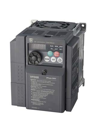
VFD68BBB Variable Frequency Drive
A VFD68 drive can control multiple motors wired in parallel; however, the sum of the Full Load Amperes (FLA) ratings for the motors must not exceed the maximum output current rating of the VFD68 drive, including any
de-rating due to altitude, temperature, or a combination of both.
IMPORTANT: Do not control both
single-phase and three-phase motors with the same VFD68 drive.
Repair Information
If the VFD68 Variable Frequency Drive fails to operate within its specifications, replace the unit. For a replacement VFD68 Drive, contact the nearest Johnson Controls® representative.
Motor Speed Controls
VFD68 Variable Frequency Drives (Continued)
![]()
![]()
![]()
![]()
Selection Charts
230 VAC ±10% Production Models
460 VAC ±10% Production Models
575 VAC +5/-10% Production Models
Accessories
| Product Code
Number |
Description | Accessory Information |
| P499RAPS100K
P499RCPS100K |
Electronic Pressure Transducer (-10 to 100 psis [sealed for wet
and freeze/thaw applications] Range) and WHA-PKD3-200C Wire Harness |
include one P499 Pressure Transducer model and a WHA-PKD3-200C (6-1/2 ft [2 m]) Wire Harness. To order a single P499 Pressure Transducer model (without a WHA-PKD3-200C Wire Harness), replace the K with a C at the end of the P499 product code number.
|
| P499RAPS102K
P499RCPS102K |
Electronic Pressure Transducer (0 to 200 psis [sealed for wet and
freeze/thaw applications] Range) and one WHA-PKD3-200C Wire Harness |
|
| P499RAP-101K
P499RCP-101K |
Electronic Pressure Transducer (0 to 100 psig Range) and
WHA-PKD3-200C Wire Harness |
|
| P499RAP-102C | Electronic Pressure Transducer (0 to 200 psig Range) | |
| P499RAP-105K
P499RCP-105K |
Electronic Pressure Transducer (0 to 500 psig Range) and
WHA-PKD3-200C Wire Harness |
|
| P499RAP-107K
P499RCP-107K |
Electronic Pressure Transducer (0 to 750 psig Range) and
WHA-PKD3-200C Wire Harness |
|
| WHA-PKD3-200C | Wire Harness with Pigtail Leads, 6-1/2 ft (2 m) | |
| WHA-PKD3-400C | Wire Harness with Pigtail Leads, 13 ft (4 m) | |
| WHA-PKD3-400C | Wire Harness with Pigtail Leads, 19-5/8 ft (6 m) |
Motor Speed Controls
VFD68 Variable Frequency Drives (Continued)
![]()
![]()
![]()
![]()
Technical Specifications
| VFD68 Variable Frequency Drive | |
| Input Power Voltage/Frequency | 230 VAC, 50 HZ (208/230 VAC, 60 Hz);
400 VAC, 50 Hz (460 VAC, 60 Hz); 575 VAC, 50 Hz; Continuous Duty |
| Output Voltage/Frequency | 230 VAC, 50 HZ (208/230 VAC, 60 Hz);
400 VAC, 50 Hz (460 VAC, 60 Hz); 575 VAC, 50 Hz; Continuous Duty |
| Input Devices | Johnson Controls/PENN® P499 Electronic Pressure Transducers |
| PWM Carrier Frequency | Adjustable 0.7 to 15 kHz |
| Motor Requirements | Three-phase NEMA Design B motors required; Inverter-rated motors recommended |
| Overload Capacity | 150% of ampere rating for 1 minute |
| Start/Stop | Use STF input to start or stop the motor |
| Ambient Conditions | Storage: -40 to 65ºC (-40 to 149ºF), 0 to 95% RH noncondensing |
| Operating: -40 to 50ºC (-40 to 122ºF), 0 to 95% RH noncondensing | |
| Altitude: 1,000 m (3,300 ft) maximum without derating | |
| Enclosures | UL Type 1 (NEMA) fan cooled
(230 VAC 1 hp and lower models do not have a fan) |
| Maximum High Voltage Wire Length | Up to 100 m (328 ft) between the VFD68 drive and the motor (using the appropriate wire gauge) |
| Compliance | North America: cULus Listed, UL 508C, CSA-C22.2 No. 14, File E244421; Industry Canada (IC) Compliant to Canadian ICES-003, Class B limits
Europe: CE Mark- Johnson Controls Inc. declares that this product is in compliance with the essential requirements and other relevent provisions of the EMC Directive and the Low Voltage Directive. Australia: Regulatory Compliance Mark (RCM) |
| Dimensions (H x W x D) | Minimum: 128 x 68 x 81 mm (5 x 2-11/16 x 3-3/16 in.)
Maximum: 260 x 220 x 190 mm (10-1/4 x 8-11/16 x 7-1/2 in.) |
| Shipping Weight | 0.5 to 3.8 kg (1.1 to 8.38 lb) |
Valves and Valve Accessories Code No. LIT-1927325
 V43/V243 Series Pressure-Actuated Water-Regulating Valves
![]()
![]()
![]()
Description
The V43/V243 Pressure Actuated Water Regulating Valves are designed to regulate water flow through the condenser of large refrigerated cooling systems. These
pilot-operated valves open on an increase in refrigerant head pressure and provide modulating operation.
The V43/V243 water regulating valves are available for commercial and maritime applications.
V43 valves are available for non-corrosive low- and medium-pressure refrigerants such as R-134A, R-404A, R-502, and R-507.
Specially designed V43 valves are also available for ammonia service (R-717).
V243 valves are available for non-corrosive high-pressure refrigerants such as R410A.
Commercial V43/V243 valves are constructed with a cast iron body, brass internal parts, and bronze seat material.
Valve Construction and Pressure Type
| Designator | Construction and Pressure Type |
| A | Commercial Service with Iron Body, Open on Pressure Increase, V43 |
| B | Maritime Service with Brass Body, Open on Pressure Increase, V43 |
| C | Navy Service with Brass Body, Open on Pressure Increase, V43 |
| G | Commercial Service with Iron Body, Open on Pressure Increase, V243 |
| H | Maritime Service with Brass Body, Open on Pressure Increase, V243 |
Flange Size
To resist the corrosive action of sea water, the V43/V243 maritime and navy models are constructed with a red brass body, bronze and monel interior parts, and monel seat material.
Refer to the V43/V243 Pressure Actuated Water Regulating Valves Product/Technical Bulletin (LIT-125683) for important product information.
Features
- built-in pilot valve allows more precise throttling
- easy adjustment allows service and adjustment without breaking line connections
- drain plug allows water to be drained during shutdown to reduce the possibility of freeze-up
- mesh monel screen protects pilot valve from items such as dirt and scale and is easily removed for cleaning and servicing without breaking any line connections
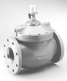
V43 Pressure Actuated Valve
Selection Charts
When ordering V43 valves, specify the complete product code number including an optional companion flange and gasket kit. A companion flange and gasket kit is required to mount the water lines to commercial type V43/V243 water-regulating valves.
| Designator | Flange Size |
| S | 2 in. |
| T | 2-1/2 in. |
| V | 3 in. |
| W | 4 in. |
V43 Series Pressure Actuated Water Valves (except NAVSEA valves)
Valves and Valve Accessories
V43/V243 Series Pressure-Actuated Water-Regulating Valves (Continued)
![]()
![]()
![]()
![]()
Selection Charts (Continued)
V43 Series Pressure Actuated Water valves, Navy NAVSEA Certified
V243 Series Pressurized Actuated Water Valves
| Product Code Number | Pipe Size (in.) | Inlet and Outlet | Opening Point Adjustment Range – psig (kPa) | Shipping Weight, lb (kg) |
| Commercial Type – High Pressure Refrigerants | ||||
| V243GS-1C | 2 | Four Hole ASME Flange | 200 to 400 (1,379 to 2,758) | 59 (26.76) |
| V243GT-1C | 2-1/2 | 65 (29.48) | ||
| V243GV-1C | 3 | 90 (40.82) | ||
| V243GW-1C | 4 | Eight Hole ASME Flange | 142 (64.41) | |
| Maritime Type – High Pressure Refrigerants | ||||
| V243HS-1C | 2 | Four Hole ASME Flange | 200 to 400 (1,379 to 2,758) | 59 (26.76) |
| V243HT-1C | 2-1/2 | 65 (29.48) | ||
| V243HV-1C | 3 | 90 (40.82) | ||
| V243HW-1C | 4 | Eight Hole ASME Flange | 142 (64.41) | |
Accessories
| Kit Code Number | Water Valve Size (in.) | Shipping Weight, lb (kg) |
| KIT14A-6131, 2 | 2 | 11.8 (5.4) |
| KIT14A-6141, 2 | 2-1/2 | 16.5 (7.5) |
| FLG15A-6001, 3 | 3 | 20 (9.1) |
| FLG15A-6011, 3 | 4 | 34 (15.4) |
- Commercial valves only.
- These are the parts included in the flange and gasket kit for the 2-inch and 2-1/2 inch valves.
- These are the parts included in the flange and gasket kit for the 3-inch and 4-inch valves.
A companion flange and gasket kit is required to mount the water lines to commercial type V43/V243 water-regulating valves.
Ring Gasket (Two)
Cast Iron Flange (Two)
Cast Iron Flange (Two) Machine Bolt (Eight)
Hex Nut (Eight)
![]()
Machine Bolt (Eight)
![]()
![]()
![]()
Hex Nut (Eight)
FIG:FLG15A
KIT14A FLG15A
![]()
![]()
![]()
![]()
![]()
Valves and Valve Accessories
V43/V243 Series Pressure-Actuated Water-Regulating Valves (Continued)
![]()
![]()
![]()
![]()
Repair and Replacement Information
If a V43/V243 Pressure-Actuated Water-Regulating Valve fails to operate within its specifications, replacement sensing elements, internal parts, and diaphragms are available for valve repair.
To obtain replacement parts, kits, instructions, and details, contact your nearest Johnson Controls® distributor at
http://cgproducts.johnsoncontrols.com/dist_locate/locateDIST.asp. For replacement parts, see Repair Parts and Parts Kits.
| Model | Diaphragm
Kit |
Seat Disc and
Diaphragm Kit |
Seat Repair
Kit |
Screen
Repair Kit |
Push Rod | Sensing
Element Kit |
Disc Body
Kit |
| V43AS-1C | DPM18A-600R | DSC16A-600R | STT19A-602R | SCN10A-600R | ROD18A-600R | SEP88A-600R | DBK11A-600R |
| V43AS-2C | DPM18A-600R | DSC16A-600R | STT19A-602R | SCN10A-600R | ROD18A-600R | SEP88A-601R | DBK11A-600R |
| V43AS-5C | DPM18A-600R | DSC16A-600R | STT19A-602R | SCN10A-600R | ROD18A-600R | SEP87A-600R | DBK11A-600R |
| V43AT-1C | DPM18A-601R | DSC16A-601R | STT19A-603R | SCN10A-600R | ROD18A-601R | SEP88A-600R | DBK11A-601R |
| V43AT-2C | DPM18A-601R | DSC16A-601R | STT19A-603R | SCN10A-600R | ROD18A-601R | SEP88A-601R | DBK11A-601R |
| V43AT-5C | DPM18A-601R | DSC16A-601R | STT19A-603R | SCN10A-600R | ROD18A-601R | SEP87A-600R | DBK11A-601R |
| V43AV-1C | DPM18A-602R | DSC16A-602R | STT19A-606R | SCN10A-600R | ROD18A-601R | SEP88A-600R | DBK11A-602R |
| V43AV-2C | DPM18A-602R | DSC16A-602R | STT19A-606R | SCN10A-600R | ROD18A-601R | SEP88A-601R | DBK11A-602R |
| V43AV-5C | DPM18A-602R | DSC16A-602R | STT19A-606R | SCN10A-600R | ROD18A-601R | SEP87A-600R | DBK11A-602R |
| V43AW-1C | DPM18A-603R | DSC16A-603R | STT19A-608R | SCN10A-600R | ROD18A-602R | SEP88A-600R | DBK11A-603R |
| V43AW-2C | DPM18A-603R | DSC16A-603R | STT19A-608R | SCN10A-600R | ROD18A-602R | SEP88A-601R | DBK11A-603R |
| V43AW-5C | DPM18A-603R | DSC16A-603R | STT19A-608R | SCN10A-600R | ROD18A-602R | SEP87A-600R | DBK11A-603R |
| V43BS-1C1 | DPM18A-600R | DSC16A-600R | STT19A-602R | SCN10A-601R | ROD18A-602R | SEP88A-600R | DBK11A-600R |
| V43BS-2C1 | DPM18A-600R | DSC16A-600R | STT19A-602R | SCN10A-601R | ROD18A-602R | SEP88A-601R | DBK11A-600R |
| V43BS-3C | DPM18A-600R | DSC16A-600R | STT19A-600R | SCN10A-601R | ROD18A-602R | SEP88A-600R | DBK10A-600R |
| V43BS-6C | DPM18A-600R | DSC16A-600R | STT19A-600R | SCN10A-601R | ROD18A-602R | SEP88A-600R | DBK10A-600R |
| V43BS-7C | DPM18A-600R | DSC16A-600R | STT19A-600R | SCN10A-601R | ROD18A-602R | SEP88A-601R | DBK10A-600R |
| V43BT-1C1 | DPM18A-601R | DSC16A-601R | STT19A-603R | SCN10A-601R | ROD18A-603R | SEP88A-600R | DBK11A-601R |
| V43BT-2C1 | DPM18A-601R | DSC16A-601R | STT19A-603R | SCN10A-601R | ROD18A-603R | SEP88A-601R | DBK11A-601R |
| V43BT-3C | DPM18A-601R | DSC16A-601R | STT19A-605R | SCN10A-601R | ROD18A-603R | SEP88A-600R | DBK10A-602R |
| V43BT-6C | DPM18A-601R | DSC16A-601R | STT19A-605R | SCN10A-601R | ROD18A-603R | SEP88A-600R | DBK10A-602R |
| V43BT-7C | DPM18A-601R | DSC16A-601R | STT19A-605R | SCN10A-601R | ROD18A-603R | SEP88A-601R | DBK10A-602R |
| V43BV-1C1 | DPM18A-602R | DSC16A-602R | STT19A-606R | SCN10A-601R | ROD18A-603R | SEP88A-600R | DBK11A-602R |
| V43BV-2C1 | DPM18A-602R | DSC16A-602R | STT19A-606R | SCN10A-601R | ROD18A-603R | SEP88A-601R | DBK11A-602R |
| V43BV-4C | DPM18A-602R | DSC16A-602R | STT19A-607R | SCN10A-601R | ROD18A-603R | SEP88A-600R | DBK10A-601R |
| V43BV-5C1 | DPM18A-602R | DSC16A-602R | STT19A-606R | SCN10A-601R | ROD18A-603R | SEP88A-600R | DBK11A-602R |
| V43BV-6C1 | DPM18A-602R | DSC16A-602R | STT19A-606R | SCN10A-601R | ROD18A-603R | SEP88A-601R | DBK11A-602R |
| V43BV-7C | DPM18A-602R | DSC16A-602R | STT19A-607R | SCN10A-601R | ROD18A-603R | SEP88A-601R | DBK10A-601R |
| V43BV-8C | DPM18A-602R | DSC16A-602R | STT19A-607R | SCN10A-601R | ROD18A-603R | SEP88A-600R | DBK10A-601R |
| V43BV-9C | DPM18A-602R | DSC16A-602R | STT19A-607R | SCN10A-601R | ROD18A-603R | SEP88A-601R | DBK10A-601R |
| V43BV-10C | DPM18A-602R | DSC16A-602R | STT19A-607R | SCN10A-601R | ROD18A-603R | SEP88A-600R | DBK10A-601R |
| V43BW-1C | DPM18A-603R | DSC16A-603R | STT19A-609R | SCN10A-601R | ROD18A-602R | SEP88A-600R | DBK10A-603R |
| V43BW-2C | DPM18A-603R | DSC16A-603R | STT19A-609R | SCN10A-601R | ROD18A-602R | SEP88A-601R | DBK10A-603R |
| V43BW-5C | DPM18A-603R | DSC16A-603R | STT19A-609R | SCN10A-601R | ROD18A-602R | SEP88A-600R | DBK10A-603R |
| V43BW-6C | DPM18A-603R | DSC16A-603R | STT19A-609R | SCN10A-601R | ROD18A-602R | SEP88A-601R | DBK10A-603R |
| V43BW-7C | DPM18A-603R | DSC16A-603R | STT19A-609R | SCN10A-601R | ROD18A-602R | SEP88A-600R | DBK10A-603R |
| V43CS-1C | DPM18A-600R | DSC16A-600R | STT19A-600R | SCN10A-601R | ROD18A-602R | SEP88A-600R | DBK10A-600R |
| V43CS-2C | DPM18A-600R | DSC16A-600R | STT19A-600R | SCN10A-601R | ROD18A-602R | SEP88A-600R | DBK10A-600R |
| V43CS-3C | DPM18A-600R | DSC16A-600R | STT19A-600R | SCN10A-601R | ROD18A-604R | SEP88A-600R | DBK10A-600R |
| V43CT-1C | DPM18A-601R | DSC16A-601R | STT19A-605R | SCN10A-601R | ROD18A-603R | SEP88A-600R | DBK10A-602R |
| V43CT-2C | DPM18A-601R | DSC16A-601R | STT19A-605R | SCN10A-601R | ROD18A-603R | SEP86A-600R | DBK10A-602R |
| V43CV-1C | DPM18A-602R | DSC16A-602R | STT19A-607R | SCN10A-601R | ROD18A-603R | SEP86A-600R | DBK10A-601R |
| V43CV-2C | DPM18A-602R | DSC16A-602R | STT19A-607R | SCN10A-601R | ROD18A-603R | SEP88A-600R | DBK10A-601R |
Valves and Valve Accessories
V43/V243 Series Pressure-Actuated Water-Regulating Valves (Continued)
![]()
![]()
![]()
![]()
Repair Parts (Part 2 of 2)
1. Replacement push rod kit requires a seat repair kit and/or a diaphragm kit when replaced.
Parts Kits
The following valves, manufactured after date code 8702, contain monel interior trim. Order replacement kits as listed in Repair Parts or
V43xx and V243xx Series Repair Parts Kits Technical Bulletin (LIT-121690).
| Valve Model | Order Parts Kits for: |
| V43BS-1C | V43BS-6C |
| V43BS-2C | V43BS-7C |
| V43BT-1C | V43BT-6C |
| V43BT-2C | V43BT-7C |
| V43BV-1C | V43BV-10C |
| V43BV-2C | V43BV-7C |
| V43BV-5C | V43BV-10C |
| V43BV-6C | V43BV-9C |
Dimensions
| Symbol | 2 Inch | 2-1/2 Inch | 3 Inch | 4 Inch |
| A1 | 9-1/2 in. (241 mm) | 10-3/4 in.(273 mm) | 11-3/4 in. (298 mm) | 14 in. (356 mm) |
| B | 7-1/2 in. (191 mm) | 8 in. (203 mm) | 9 in. (229 mm) | 10-3/4 in. (273 mm) |
| C | 4-3/4 in. (121 mm) | 5-1/2 in. (140 mm) | 6 in. (152 mm) | 7-1/2 in. (191 mm) |
| D | 6 in. (152 mm) | 7 in. (178 mm) | 7-1/2 in. (191 mm) | 9 in. (229 mm) |
| E | 2-1/8 in. (54 mm) | 2-5/8 in. (67 mm) | 3-1/8 in. (80 mm) | 4-1/8 in. (105 mm) |
| F2 | 15-1/4 in. (387 mm) | 15-9/16 in. (395 mm) | 16-9/16 in. (421 mm) | 18-7/32 in. (462 mm) |
| F3 | 15-29/32 in. (404 mm) | 16-7/32 in. (412 mm) | 17-7/32 in. (437 mm) | 18-7/8 in. (479 mm) |
| G | 3/4 in. (19 mm) Diameter (Four) | 3/4 in. (19 mm) Diameter (Four) | 3/4 in. (19 mm) Diameter (Four) | 3/4 in. (19 mm) Diameter (Eight) |
| H | 3-5/8 in. (92 mm) | 3-15/16 in. (100 mm) | 4-1/4 in. (108 mm) | 5-1/16 in. (128 mm) |
- Flange face to flange face.
- These are the measurements for the V43 valves.
- These are the measurements for the V243 valves.
Valves and Valve Accessories
V43/V243 Series Pressure-Actuated Water-Regulating Valves (Continued)
![]()
![]()
![]()
![]()
Six- and Eight- Flange Hole Configurations
![]()
![]()
![]()
![]()
![]()
![]()
G
E
D
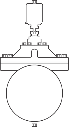
![]()
![]()
F
D
C
G
H
B
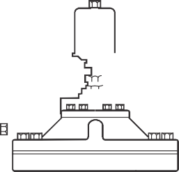
![]()
![]()
![]()
![]()
A
| E |
![]()
![]()
![]()
![]()
![]()
![]()
![]()
![]()
E
G
D
V43/V243 Pressure Actuated Water Regulating Valves Dimensions
FIG:Dimensions
V43 Capacity Flow Charts
CAPACITY CHART FOR 2 in. VALVE
Low Pressure Refrigerants
CAPACITY CHART FOR 3 in. VALVE
Low Pressure Refrigerants
Water Pressure Available Across Valve (psi) Water Pressure Available Across Valve (psi)
Refrigerant Head Pressure Rise Above Valve Opening Point (psig)
Refrigerant Head Pressure Rise Above Valve Opening Point (psig)
10 20 30 50
50 40
40 30
30
20
20
10 10
0 0
50 40
40 30
30
20
20
10 10
0 0
10 20 30 50
50 100 150 200 250 300 350 400 450
Water Flow (GPM)
Medium Pressure Refrigerants
100 200 300 400 500 600 700 800 900
Water Flow (GPM)
Medium Pressure Refrigerants
CAPACITY CHART FOR 2-1/2 in. VALVE
Low Pressure Refrigerants
Water Pressure Available Across Valve (psi)
Refrigerant Head Pressure Rise Above Valve Opening Point (psig)
CAPACITY CHART FOR 4 in. VALVE
Low Pressure Refrigerants
Water Pressure Available Across Valve (psi)
Refrigerant Head Pressure Rise Above Valve Opening Point (psig)
10 20 30 50
50 40
40 30
30
20
20
10 10
0 0
50 40
40 30
30
20
20
10 10
0 0
5 10 20 30 50
50 100 150 200 250 300 350 400 450
Water Flow (GPM)
Medium Pressure Refrigerants
150 300 450 600 750 900 1050 1200 1350
Water Flow (GPM)
Medium Pressure Refrigerants
Valves and Valve Accessories
V43/V243 Series Pressure-Actuated Water-Regulating Valves (Continued)
![]()
![]()
![]()
![]()
V243 Capacity Flow Charts
CAPACITY CHART FOR 2 in. VALVE
CAPACITY CHART FOR 3 in. VALVE
Refrigerant Head Pressure Rise Above Valve Opening Point (psig)
Water Pressure Available Across Valve (psi)
Refrigerant Head Pressure Rise Above Valve Opening Point (psig)
Water Pressure Available Across Valve (psi)
2 5 10 14.5 20 2530
60
40
20
40 50 60
2 5 10 14.5
60
40
20
20 25 30 40 50 60
0
50 100 150 200 250 300 350 400 450
Water Flow (GPM)
0
100 200 300 400 500 600 700 800 900
Water Flow (GPM)
CAPACITY CHART FOR 2-1/2 in. VALVE
CAPACITY CHART FOR 4 in. VALVE
Water Pressure Available Across Valve (psi) Water Pressure Available Across Valve (psi)
Refrigerant Head Pressure Rise Above Valve Opening Point (psig)
Refrigerant Head Pressure Rise Above Valve Opening Point (psig)
2 5 1014.5 20 2530 40
60
40
20
50 60
2 5 10
60
40
20
14.5
20 25 30
40 50 60
0
100 200 300 400 500 600 700 800 900
Water Flow (GPM)
0
100 200 300 400 500 600 700 800 900 1000 1100 1200 1300
Water Flow (GPM)
Technical Specifications
| V43/V243 Pressure-Actuated Water-Regulating Valves | |||
| Maximum Water Supply Pressure | 150 psig (1,034 kPa) | ||
| V43 Maximum Head Pressure | 300 psig (2,068 kPa) | ||
| V243 Maximum Head Pressure | 630 psig (4,344 kPa) | ||
| Head Pressure Range (Opening Points) | V43 | Low Pressure Refrigerants | R-134A – 70 to 150 psig (482 to 1,034 kPa) |
| Medium Pressure Refrigerants | R-22, R-502, R404A – 160 to 260 psig (1,103 to 1,793 kPa) | ||
| Ammonia | 160 to 260 psig (1,103 to 1,793 kPa) | ||
| V243 | High Pressure | 200 to 400 psig (1,379 to 2,758 kPa) | |
| Factory Settings1 | V43 | Low Pressure Refrigerants | 90 psig (621 kPa) |
| Medium Pressure Refrigerants | 180 psig (1,241 kPa) | ||
| Ammonia | 180 psig (1,241 kPa) | ||
| V243 | High Pressure | 200 psig (1,379 kPa) | |
| Maximum Water Supply Temperature | 160°F (71°C) | ||
| Valve Body Material | Commercial | Cast iron | |
| Maritime | Red brass | ||
| Internal Parts Material | Commercial | Brass | |
| Maritime | Bronze, Monel | ||
| Seat Material | Pilot | Monel | |
| Main Valve | Commercial – Bronze, Maritime – Monel | ||
| Seat Disc Material | Buna N™ | ||
| Packing – Bellows Assembly | Brass stem, stainless steel spring, synthetic rubber boot | ||
| Pressure Connection Refrigerant Side | Non-Corrosive | 1/4 in. SAE External Flare | |
| Ammonia | 1/4 in. FNPT | ||
1. Factory opening setpoint for the valve is adjustable.
Valves and Valve Accessories Code No. LIT-1927350
 V46 Series Pressure Actuated Water Regulating Valve
![]()
![]()
![]()
Description
The V46 is a pressure actuated modulating valve that is suitable for use either on closed or open systems. Direct acting valves open on pressure increase. This type of valve is primarily used to regulate the flow of water or glycol to a water cooled condenser on a refrigeration system.
Refer to the V46 Pressure-Actuated Water-Regulating Valve Product Bulletin (LIT-125687) for important product application information.
Features
- no close fitting or sliding parts in water passages
- minimizes chatter or water hammer
- free movement of all parts provides smooth pressure modulation
- refrigerant adjustment is not affected by water pressure
- withstands high hydraulic shock without damage
- range spring does not come in contact with cooling water
- easy manual flushing, if required
- 3/8, 1/2, and 3/4 in. valves may be disassembled and reassembled without detaching from the refrigeration system or
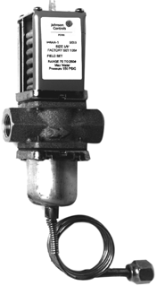
V46AA-1 Water Regulating Valve
Repair Information
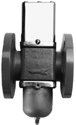
V46AT-1 Water Regulating Valve
without pumping down
Applications
This valve is designed to modulate flow of water or glycol to a water cooled condenser on a refrigeration system.
If the V46 Series Pressure Actuated Water Regulating Valve fails to
operate within its specifications, replace the unit. For a replacement valve, contact the nearest Johnson Controls® representative.
- ice machines
- computer room air conditioning units
Selection Chart
- ice cream machines
- refrigeration cases
| Product Code
Number1 |
Pipe
Size (In.) |
Inlet and
Outlet |
Opening Point
Range – psig (kPa) |
Pressure Element
Style2 |
Seat Repair
Kit |
Replacement
Power Elements |
| Commercial Type, Standard Flow – Non-Corrosive Refrigerant | ||||||
| V46AA-1C | 3/8 NPT | Threaded | 70 to 260 (483 to 1,793) | 30 in Capillary; 1/4 in. Flare Nut (Style 45) | STT14A-600R | SEP91A-600R and SEC99AA-36C3 |
| V46AA-50C | 1/4 in. External Flare Fitting (Style 5) | SEP91A-600R | ||||
| V46AB-1C | 1/2 NPT | 30 in Capillary; 1/4 in. Flare Nut (Style 45) | STT15A-602R | SEP91A-602R and SEC99AA-36C3 | ||
| V46AB-25C | 1/4 in. External Flare Fitting (Style 5) | SEP91A-602R | ||||
| V46AC-1C | 3/4 NPT | 30 in Capillary; 1/4 in. Flare Nut (Style 45) | STT16A-601R | SEP91A-601R and SEC99AA-36C3 | ||
| V46AC-26C | 1/4 in. External Flare Fitting (Style 5) | SEP91A-601R | ||||
| V46AD-1C | 1 NPT | 30 in Capillary; 1/4 in. Flare Nut (Style 45) | STT17A-609R | SEP91A-603R and SEC99AA-36C3 | ||
| V46AD-13C | 1/4 in. External Flare Fitting (Style 5) | SEP91A-603R | ||||
| V46AE-1C | 1 1/4 NPT | 30 in Capillary; 1/4 in. Flare Nut (Style 45) | STT17A-610R | SEP91A-603R and SEC99AA-36C3 | ||
| V46AE-17C | 1/4 in. External Flare Fitting (Style 5) | SEP91A-603R | ||||
| V46AJ-2C | 1/2 | Union | 48 in Capillary; 1/4 in. Flare Nut (Style 46) | STT15A-602R | SEP77A-605R | |
| V46EK-2C | 3/4 | STT16A-601R | SEP127A-600R | |||
| V46AL-2C | 1 | STT17A-609R | SEP107A-602R | |||
| V46AM-2C | 1-1/4 | STT17A-610R | ||||
| V46AR-1C | 1 1/2 | Four Hole ASME Flange | 30 in Capillary; 1/4 in. Flare Nut (Style 45) | SEP91A-603R and SEC99AA-36C3 | ||
| V46AR-10C | 1/4 in. External Flare | SEP91A-603R | ||||
| V46AS-1C | 2 | 70 to 170 (483 to 1,172) | STT18A-600R | SEP81A-602R | ||
| V46AS-2C | 2 | 160 to 260 (1,103 to 1,793) | SEP81A-601R | |||
| V46AT-1C | 2-1/2 | 70 to 170 (483 to 1,172) | STT18A-601R | SEP81A-602R | ||
| V46AT-2C | 2-1/2 | 160 to 260 (1,103 to 1,793) | SEP81A-601R | |||
Valves and Valve Accessories
V46 Series Pressure Actuated Water Regulating Valve (Continued)
![]()
![]()
![]()
![]()
- Refer to V46 Series Valve Sizing Information — 90% Open Method (LIT-1927400). Then specify the code number from this chart. Refer to the Accessories chart on the following page for companion flange kit code numbers.
- Standard capillary length on Style 45 and Style 34 elements is 30 inches
- Replacement element supplied with 1/4 in. external SAE connector. Order SEC99AA Capillary Kit with 2 flare nuts separately, if needed.
- Low water flow valve – 2.5 GPM max.
- Replacement element supplied with 1/4 in. external SAE connector. Order SEC99AA Capillary Kit with 2 flare nuts separately, if needed.
Note: Use only on valves specified.
Valves and Valve Accessories
V46 Series Pressure Actuated Water Regulating Valve (Continued)
![]()
![]()
![]()
![]()
Accessories (Companion Flanges and Gaskets)
Ring Gasket (Two)
Cast Iron Flange (Two)
Machine
![]()
| Product Code Number | Water Valve
Size (in.) |
|
| Flange Gasket
(One Gasket per Package) |
Companion Flange Kit
(See Diagram) |
|
| 246-423 | KIT14A-6121 | 1-1/2 in. |
| 246-424 | KIT14A-6131 | 2 in. |
| 246-425 | KIT14A-6141 | 2-1/2 in. |
![]()
![]()
![]()
Note: Flange has NPT (National Pipe Thread)
Companion Flange Kit
Technical Specifications
| V46 Series Pressure Actuated Water Regulating Valves | ||
| Maximum Water Temperature | 170°F (77°C) | |
| Valve Body | Commercial | 3/8 to 3/4 in. cast brass, 1 in. and larger cast iron with a special finish |
| Navy and Maritime | Cast naval bronze with Monel® interior parts | |
Pressure Range Specification
| Refrigerant | Opening Point Range1 – psig (kPa)
V46A B, C, D |
Maximum Permissible Pressure
psig (kPa) |
||
| Water | Refrigerant | |||
| Static | P Across Valve | |||
| Non-Corrosive Refrigerants (R12, R22, R134a, R502, R404a, R507) | ||||
| All Range Valve | 70 to 260 (483 to 1,793) | 150 (1,034) | 60 PST | 320 (2,206) |
| All Range with High Overpressure | 370 (2,551) | |||
| 3/8 in. Extended All Range | 70 to 300 (483 to 2,068) | 440 (3,034) | ||
| Valves 2 in. or Larger | ||||
| R12, R134a – 2 and 2-1/2 in. Low Range | 70 to 170 (483 to 1,172) | 150 (1,034) | 60 PST | 230 (1,586) |
| R22, R502, R404a, R507 – 2 and 2-1/2 in. High Range | 160 to 260 (1,103 to 1,793) | 320 (2,206) | ||
| Other Refrigerants | ||||
| Ammonia R717 | 100 to 200 (690 to 1,379) | 150 (1,034) | 60 PST | 320 (2,206) |
1. Direct acting valve ranges indicate the valve opening point.
Valves and Valve Accessories Code No. LIT-1927335
V46N Series Reverse Acting Valve
![]()
![]()
![]()
![]()
Description
The V46N Series are reverse acting pressure actuated modulating valves used on either open or closed loop coolant systems.
Reverse acting valves open on a refrigerant pressure decrease. They are generally used in parallel with a direct acting valve for heat pump applications or for bypass operation.
Refer to the V46 Pressure-Actuated Water-Regulating Product Bulletin (LIT-125687) for important product application information.
Selection Chart
Applications
- bypass systems
- water cooled heat pumps in parallel with direct acting valve
Repair Information
If the V46N Series Reverse Acting Valve fails to operate within its specifications, replace the unit. For a replacement valve, contact the nearest Johnson Controls® representative.
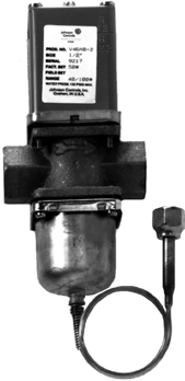
V46 Series Reverse Acting Valve
| Product Code
Number1 |
Pipe Size
In. |
Inlet and
Outlet |
Opening Point
Range psig (kPa) |
Pressure Element
Style |
Seat Repair Kit | Replacement
Power Elements |
| Commercial Type – Non-Corrosive Refrigerants (R) | ||||||
| V46NA-1C | 3/8 NPT | Threaded | 90 to 280 (621 to 1,931) | 30 in. capillary with
1/4 in. flare nut |
STT14A-600R | SEP91A-600R & SEC99AA-36C2 |
| V46NA-4C | 40 to 1003 (276 to 690) | |||||
| V46NB-1C | 1/2 NPT | 90 to 280 (621 to 1,931) | STT15A-602R | SEP91A-602R & SEC99AA-36C2 | ||
| V46NB-2C | 40 to 1003 (276 to 690) | |||||
| V46NC-1C | 3/4 NPT | 90 to 280 (621 to 1,931) | STT16A-601R | SEP91A-601R & SEC99AA-36C2 | ||
| V46NC-2C | 40 to 1003 (276 to 690) | |||||
| V46ND-1C | 1 NPT | 90 to 280 (621 to 1,931) | STT17A-609R | SEP91A-603R & SEC99AA-36C2 | ||
| V46ND-2C | 40 to 1003 (276 to 690) | |||||
| V46NE-1C | 1-1/4 NPT | 90 to 280 (621 to 1,931) | STT17A-610R | |||
| V46NE-2C | 40 to 1003 (276 to 690) | |||||
- Refer to V46 Series Valve Sizing Information — 90% Open Method (LIT-1927400), and then specify the code number from this chart.
- Maximum bellows overpressure is 320 psig (2,206 kPa). Replacement element provided with 1/4 in. external SAE connector. Order SEC37A capillary kit with two flare nuts, separately if needed. Use only on valves specified.
- For heat pump application.
Valves and Valve Accessories Code No. LIT-1927400
 V46 Series Valve Sizing Information—90% Open Method
![]()
![]()
![]()
To Select Water Valve Size:
300 Flow Chart 1136
See the Flow Chart for selection of water valves. Carefully follow the steps as outlined below.
- Determine maximum water flow required. The manufacturer of the condensing unit will usually provide tables, or calculations can be made from the following:
- Maximum Btu per hour to be removed. (Be sure to add heat gains in refrigeration equipment and heat of compression. If figures are not available, it is customary to add 25% to the load for these heat gains.)
Water Flow In Gallons/Minute
-
- Incoming water temperature at time of maximum load.
- Outlet water temperature; this must be lower than condensing temperature of the refrigerant
– use condensing unit manufacturer’s data, or assume 10° difference.
v46size.eps
-
- Flow (gallons/min) =
l 6 L 6L9l ln
Onll6l l6Wb6L9lnL6 – l l6l l6Wb6L9lnL6
- Draw horizontal line across upper half of flow chart through flow required as determined by Step 1d above.
- Determine the available system pressure for use with the valve by the following appropriate method:
Open System:
Available System Pressure = Inlet Pressure – condenser pressure drop – friction losses in piping.
200
100
90
80
70
60
50
40
30
20
10
9
8
7
6
5
4
3
2
1
Refrig. Head Press. Above Opening PT. (PSI)
Valve Size
3/8 in. thru 1-1/2 in.
2 in., 2-1/2 in.
Refrigerant
All-range R-12, R-500, R-22, R-502,
Ammonia, R-12, R-500
2-1/2
1-1/2
1
1-1/4
2
3/4
1/2
757
379
341
303
256
227
Water Flow In Liters/Minute
189
151
114
76
3/8
38
34
30
26
23
19
15
11
7
3.8
Closed System:
Available System Pressure = Inlet Pressure – static head – condenser pressure drop – friction
(14)
60 414
losses in piping.
50 2
5 10
20 30
40 50 6
345
The available system pressure is represented by the curve in the lower half of the flow chart.
4 Draw a horizontal line from 55 psi head pressure
| rise above opening point (valve approximately | 40 | 276 |
| 90% open) to the available system pressure. If the | ||
| point falls between two curves, use the curve to | ||
| the left (this gives an automatic safety factor).
5 From the point where the horizontal line intersects |
30 | 207 |
| the available system pressure curve, draw a |
(34)
(69)
(138)
(207)
(276)
(345) (414)
vertical line upwards until it intersects with the horizontal line from Step 2.
- If the intersection falls on a valve size curve, this is the valve size.
- If the intersection falls between two curves, use the curve to the left for the required valve size.
20 138
10 69
0 0
Water Pressure Drop Through Valve PSI (kPa)
Flow Chart, V46 Valve
flowch1
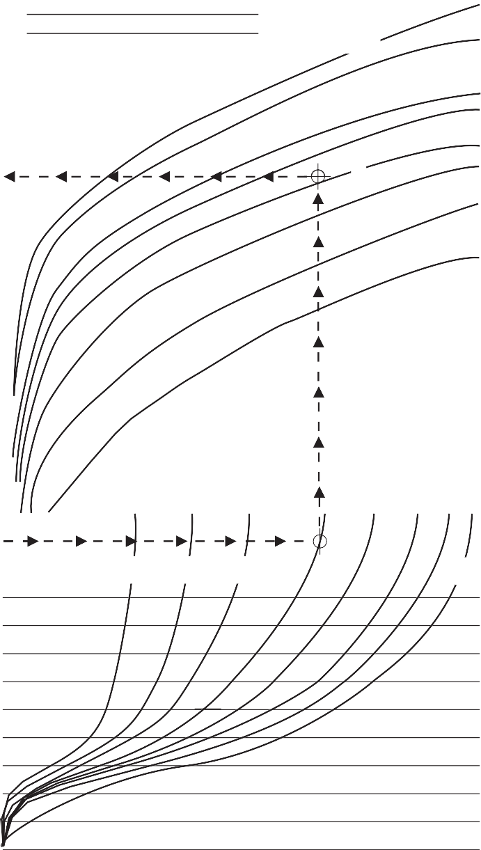
Refrig. Head Press. Above Opening PT. (kPa)
Example:
- The required flow of an R404A system is found to be 40 GPM (151 l/m).
City water pressure is 40 psig (276 kPa) and manufacturer’s table gives drop through condenser and accompanying piping and valves at 15 psi (103 kPa) drop through installed piping approximately 5 psi (35 kPa), leaving a net pressure drop available of 20 psi.
- Draw a line through 40 GPM (151 l/m) – see dotted line, upper half of flow chart.
- Size valves at 55 psi head pressure rise above opening point (valve is approximately 90% open).
- Draw a line through 55 psi (375 kPa) – see dotted line, lower half of flow chart.
- Available water pressure drop through valve
= 40 – 20 = 20 psi (276 – 137 = 137 kPa).
- Draw vertical line upward from this point to flow line – circle on flow chart marks this intersection.
- Since the intersection falls between curves for 1 in. and 1-1/4 in. valves, choose the larger size. A 1-1/4 in. valve is required.
![]()
![]()
![]()
Valves and Valve Accessories
![]()
Roughing-in Dimensions
![]()
![]()
![]()
![]()
(A)
(E)
![]()
![]()
![]()
![]()
![]()
(D)
(C)
(B)
(G)
(F)
Commercial Service: V46 Threaded Connection Dimensions
| Valve
Size |
Dimensions in Inches | ||||||
| A | B | C | D | E | F | G | |
| 3/8 in. | 2-5/8 | 6-3/4 | 3-1/8 | 1-1/2 | 1-1/4 | 13/32 | 3-7/32 |
| 1/2 in. | 3-1/8 (3-1/4)1 | 7-13/32 | 3-3/8 | 1-27/32 | 1-1/2 | 13/32 | 3-5/8 |
| 3/4 in. | 3-3/8 (3-5/8)1 | 7-7/8 | 3-7/8 | 2-1/32 | 1-3/4 | 13/32 | 3-21/32 |
| 1 in. | 4-1/2 (4-7/8)1 | 10-3/4 | 5-1/2 | 2-25/32 | 2 | 1/2 | 4-3/4 |
| 1-1/4 in. | 4-7/8 | 11-1/8 | 5-3/4 | 2-5/8 | 2-3/8 | 1/2 | 4-29/32 |
1. Values in parenthesis are for maritime valves. All other dimensions remain the same.
V46 Series Threaded Type Valves
![]()
![]()
![]()
![]()
![]()
![]()
![]()
![]()
![]()

![]()
![]()
![]()
(E)
(G)
(H)
![]()
![]()
![]()
![]()
![]()
![]()
![]()
![]()
(A)
(D)
(C)
(B)
(I)
v46tbfg4.eps
(F)
Flange Type Valves
v46tbfg5.eps
Commercial Service: V46 Flange Connection Dimensions
| Valve
Size |
Dimensions in Inches | V46 Flange Specifications | ||||||||||
| A | B | C | D | E | F | G | H | I | No. of Holes | Hole Size | Bolt Circle | |
| 1-1/2 in. | 5-5/16 | 11-1/8 | 5-3/4 | 9/16 | 5 | 1-7/8 | 2-5/8 | 1/2 | 4-29/32 | 4 | 5/8 | 3-7/8 |
| 2 in. | 6-5/8 | 13 | 6-15/32 | 5/8 | 6 | 2-1/4 | 3-1/2 | 1/2 | 6-1/8 | 4 | 3/4 | 4-3/4 |
| 2-1/2 in. | 6-3/4 | 13-1/2 | 6-3/8 | 3/4 | 7 | 2-23/32 | 3-1/2 | 1-1/32 | 6-3/32 | 4 | 3/4 | 5-1/2 |
Maritime Service: ASME Flange Connection Dimensions
| Valve
Size |
Dimensions in Inches | ASME Flange Specifications | ||||||||||
| A | B | C | D | E | F | G | H | I | No. of Holes | Hole Size | Bolt Circle | |
| 1-1/2 in. | 5-5/16 | 10-1/2 | 5-5/8 | 9/16 | 5 | 1-7/8 | 2-5/8 | 1/2 | 5 | 4 | 5/8 | 3-7/8 |
| 2 in. | 6-3/8 | 13-1/8 | 6-1/2 | 1/2 | 6 | 2-3/4 | 3-1/2 | 5/8 | 6 | 4 | 3/4 | 4-3/4 |
| 2-1/2 in. | 6-3/4 | 13-1/8 | 6-1/2 | 11/16 | 7 | 2-3/4 | 3-1/2 | 5/8 | 6 | 4 | 3/4 | 5-1/2 |
Navy BuShips Service: Navy Flange Connection Dimensions
| Valve
Size |
Dimensions in Inches | Navy Flange Specifications | ||||||||||
| A | B | C | D | E | F | G | H | I | No. of Holes | Hole Size | Bolt Circle | |
| 3/4 in. | 4-3/16 | 7-3/4 | 4 | 7/16 | 3-13/16 | 1-1/8 | 2-1/32 | 1/2 | 3-5/16 | 4 | 9/16 | 2-11/16 |
| 1 in | 5-5/16 | 9 | 4-1/2 | 1/2 | 4-1/4 | 1-1/4 | 2-5/8 | 1/2 | 4 | 4 | 9/16 | 3-1/8 |
| 1-1/4 in. | 5-5/16 | 9-11/32 | 4-11/16 | 1/2 | 4-1/2 | 1-5/8 | 2-5/8 | 1/2 | 4-5/32 | 4 | 9/16 | 3-3/8 |
| 1-1/2 in. | 5-5/16 | 10-7/32 | 5-3/4 | 1/2 | 5-1/16 | 1-7/8 | 2-5/8 | 1/2 | 4 | 6 | 9/16 | 3-15/16 |
| 2 in. | 6-3/8 | 14-1/8 | 6-13/32 | 1/2 | 5-9/16 | 2-3/4 | 3-1/2 | 7/16 | 7-9/32 | 6 | 9/16 | 4-7/16 |
| 2-1/2 in. | 6-3/8 | 14-5/16 | 6-1/2 | 1/2 | 6-1/8 | 2-3/4 | 3-1/2 | 5/8 | 7-3/16 | 6 | 9/16 | 5 |
Valves and Valve Accessories Code No. LIT-1927330
V47 Series Temperature Actuated Modulating Valve
![]()
![]()
![]()
![]()
Description
The V47 is a temperature actuated modulating valve that regulates the flow of water or glycol to maintain a desired temperature. Three temperature ranges for each valve size are available.
Many valves come with a removable bypass plug that can be replaced by the bypass orifice provided separately with each valve.
Valve action is open on temperature increase. For open on temperature decrease models, contact Application Engineering.
Refer to the V47 Series Temperature Actuated Modulating Water Valves Product Bulletin (LIT-125690) for important product application information.
Selection Chart
Features
- no close fitting sliding parts in water passages
- range spring does not come in contact with the cooling water
- easy manual flushing, if required
- valve design minimizes chatter and water hammer
Repair Information
If the V47 Series Temperature Actuated Modulating Valve fails to operate within its specifications, replace the unit. For a replacement valve, contact the nearest Johnson Controls® representative.
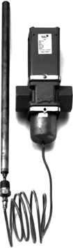
V47 Series Valve
| Product Code | Pipe Size, in. | Range
(Opening Point) °F |
Bulb Size, in. (Dia. length) | Std Bypass Orifice Dia., in. | Seat Repair Kit | Replacement Sensing Element | Bulb Well Number Order Separately |
| V47AA-1C | 3/8 | 115 to 180 Heating | 11/16 x 3-1/4 | 0.062 | STT14A-600R | SET29A-622R | WEL18A-602R |
| V47AA-2C | 3/8 | 160 to 230 Heating | 11/16 x 3-1/4 | 0.062 | STT14A-600R | SET29A-623R | WEL18A-602R |
| V47AA-3C | 3/8 | 75 to 135 Cross Ambient | 11/16 x 6 | 0.062 | STT14A-600R | SET29A-601R | WEL17A-601R |
| V47AA-26C2 | 3/8 | 20 to 65 Cross Ambient | 11/16 x 63 | – | STT14A-600R | – | WEL17A-601R |
| V47AB-2C | 1/2 | 75 to 135 Cross Ambient | 11/16 x 103 | – | STT15A-602R | SET29A-602R | WEL17A-600R |
| V47AB-3C | 1/2 | 115 to 180 Heating | 11/16 x 3-1/4 | 0.062 | STT15A-602R | SET29A-624R | WEL18A-602R |
| V47AB-4C | 1/2 | 160 to 230 Heating | 11/16 x 3-1/4 | 0.062 | STT15A-602R | SET29A-625R | WEL18A-602R |
| V47AB-5C | 1/2 | 75 to 135 Cross Ambient | 11/16 x 10 | 0.062 | STT15A-602R | SET29A-602R | WEL17A-600R |
| V47AB-27C4 | 1/2 | 40 to 85 Cross Ambient | 11/16 x 103 | Yes5 | STT15A-602R | – | WEL17A-600R |
| V47AC-3C | 3/4 | 115 to 180 Heating | 11/16 x 3-1/4 | 0.062 | STT16A-601R | SET29A-626R | WEL18A-602R |
| V47AC-4C | 3/4 | 160 to 230 Heating | 11/16 x 3-1/4 | 0.062 | STT16A-601R | SET29A-627R | WEL18A-602R |
| V47AC-6C | 3/4 | 75 to 135 Cross Ambient | 11/16 x 10 | 0.062 | STT16A-601R | SET29A-604R | WEL17A-600R |
| V47AC-8C | 3/4 | 75 to 135 Heating | 11/16 x 3-1/4 | – | STT16A-601R | SET98A-621R | WEL18A-602R |
| V47AC-40C | 3/4 | 40 to 85 Cross Ambient | 11/16 x 10 | Yes5 | STT16A-601R | – | WEL17A-600R |
| V47AD-1C | 1 | 75 to 135 Cross Ambient | 11/16 x 16-1/4 | 0.093 | STT17A-609R | SET29A-605R | – |
| V47AD-2C | 1 | 115 to 180 Heating | 11/16 x 6 | 0.093 | STT17A-609R | SET29A-629R | WEL17A-601R |
| V47AD-3C | 1 | 160 to 230 Heating | 11/16 x 6 | 0.093 | STT17A-609R | SET29A-630R | WEL17A-601R |
| V47AD-19C | 1 | 40 to 85 Cross Ambient | 11/16 x 16-1/4 | 0.093 | STT17A-609R | – | – |
| V47AE-1C | 1-1/4 | 75 to 135 Cross Ambient | 11/16 x 16-1/4 | 0.093 | STT17A-610R | SET29A-605R | – |
| V47AE-2C | 1-1/4 | 115 to 180 Heating | 11/16 x 6 | 0.093 | STT17A-610R | SET29A-629R | WEL17A-601R |
| V47AE-3C | 1-1/4 | 160 to 230 Heating | 11/16 x 6 | 0.093 | STT17A-610R | SET29A-630R | WEL17A-601R |
| V47AE-13C | 1-1/4 | 40 to 85 Cross Ambient | 11/16 x 16-1/4 | Yes5 | STT17A-610R | – | – |
| V47AR-1 | 1-1/26 | 75 to 135 Cross Ambient | 11/16 x 16-1/4 | 0.093 | STT17A-610R | SET29A-605R | – |
| V47AR-2 | 1-1/26 | 115 to 180 Heating | 11/16 x 6 | 0.093 | STT17A-610R | SET29A-629R | WEL17A-601R |
| V47AR-3 | 1-1/26 | 160 to 230 Heating | 11/16 x 6 | 0.093 | STT17A-610R | SET29A-630R | WEL17A-601R |
| V47AS-1 | 26 | 115 to 160 Heating | 11/16 x 10 | 0.125 | STT18A-600R | SET29A-632R | WEL17A-600R |
| V47AS-2 | 26 | 160 to 205 Heating | 11/16 x 10 | 0.125 | STT18A-600R | SET29A-633R | WEL17A-600R |
| V47AS-3 | 26 | 75 to 115 Cross Ambient | 11/16 x 43 | 0.125 | STT18A-600R | SET29A-606R | – |
| V47AS-13C | 26 | 40 to 85 Cross Ambient | 11/16 x 43 | Yes5 | STT18A-600R | – | – |
| V47AT-1 | 2-1/26 | 115 to 160 Heating | 11/6 x 10 | 0.125 | STT18A-601R | SET29A-632R | WEL17A-600R |
| V47AT-2 | 2-1/26 | 160 to 205 Heating | 11/6 x 10 | 0.125 | STT18A-601R | SET29A-633R | WEL17A-600R |
| V47AT-3 | 2-1/26 | 75 to 115 Cross Ambient | 11/16 x 43 | 0.125 | STT18A-601R | SET29A-606R | – |
- Standard capillary is 6 ft (Style 4)
- 2 ft capillary
- Style 1 bulb (does not include 1/2 in. external NPT fitting)
- 4 ft capillary
- Solid plug installed, orifice available separately
- ASME Flange
Note: For more information on Bulb Wells, refer to Bulb Wells (LIT-1922135).
Valves and Valve Accessories
V47 Series Temperature Actuated Modulating Valve (Continued)
![]()
![]()
![]()
![]()
Accessories (Companion Flanges and Gaskets)
| Product Code Number | Water Valve
Size (in.) |
|
| Flange Gasket
(One Gasket per Package) |
Companion Flange Kit
(See Diagram) |
|
| 246-423 | KIT14A-612 | 1-1/2 in. |
| 246-424 | KIT14A-613 | 2 in. |
| 246-425 | KIT14A-614 | 2-1/2 in. |
Ring Gasket (Two)
Cast Iron Flange (Two)
Machine Bolt (Eight)
![]()
![]()
![]()
Note: Flanges have NPT (National Pipe Thread).
Technical Specifications
| V47 Series Temperature Actuated Modulating Valves | |
| Maximum Bulb Temperature | 20F° (-6.7 C°) above temperature range |
| Maximum Water Temperature | 170°F (77°C) |
| Maximum Supply Water Pressure | 150 psig (1,034 kPa) |
| Capillary | Nylon Armor1 |
| Temperature Bulb Style 42 (pictured) | (1/2 in. NPT closed tank immersion) |
![]()
Companion Flange Kit Metric Conversion
- For capillary length, refer to the selection chart on the previous page.
| °F | °C |
| 20 to 65 | -6 to 18 |
| 40 to 85 | 4 to 29 |
| 75 to 115 | 24 to 46 |
| 75 to 135 | 24 to 57 |
| 115 to 160 | 46 to 71 |
| 115 to 180 | 46 to 82 |
| 160 to 205 | 71 to 96 |
| 160 to 230 | 71 to 110 |
- V47AA-26, V47AB-2, V47AB-27 — Temperature Bulb Style 1 (no 1/2 in. NPT external fitting)
V47 Valve Sizing Information
To Select Water Valve Size, see the flow chart for
300 1136
2-1/2
selection of water valves. Carefully follow the steps as outlined below.
- Determine the maximum water flow required. Draw a horizontal line through this flow across the upper half of the flow chart.
- Use the following method to determine the temperature rise above the opening point.
- Valve closing point is the highest temperature at which it is desired to have no flow through the valve.
- Valve opening point is about 5F° above the closing point.
- Determine the temperature the valve is to maintain, this is the operating temperature.
- Subtract the opening temperature from the operating temperature. This is the temperature rise above the opening point.
- Determine the available system pressure for use with the valve by the following appropriate method:
Open System:
Available System Pressure = Inlet Pressure – condenser pressure drop – friction losses in piping. Closed System:
Available System Pressure = Inlet Pressure –
200
100
90
80
70
60
50
40
30
20
Water Flow Gal. / Min.
10
9
8
7
6
5
4
3
2
36
2 5 10
2
1-1/2
1-1/4
1
3/4
1/2
3/8
50
20 30 40 (345)
757
379
349
303
265
227
189
151
114
76
Water Flow L/Min.
38
34
30
26
23
19
15
11
7
3.8
2
static head – condenser pressure drop-friction losses in piping.
The available system pressure is represented by
the curve in the lower half of the flow chart.
30
Temperature
(14)
(34)
(69)
(138)
(207)
(276)
-1
60 Temperature
- In the lower half of the flow curve, draw a horizontal line from the temperature above the opening point (Step 2d) to the available system pressure (Step 3). If the point falls between two pressure drop curves, use the curve to the left (this gives an automatic factor of safety).
- From this point, draw a vertical line until it intersects the flow line from Step 1.
- If the intersection falls on a valve size curve, this is the valve size.
- If the intersection falls between two curves, use the curve to the left for the required valve size.
Rise 24 Above
Opening Point o
( F)
18
12
6
0
Flow Chart, V47 Valve
(414)
-4 Rise Above
Opening Point o
( C)
-8
-11
v47_flowchart.eps
-14
-18
Valves and Valve Accessories Code No. LIT-1900107
V47N Series Reverse Acting Valve
![]()
![]()
![]()
![]()
Description
The V47N Series are reverse-acting, temperature-actuated, modulating valves that regulate the flow of water or glycol to maintain a desired temperature. Reverse-acting valves open on a drop in temperature. They are generally used in parallel with direct-acting valves for hand pump applications or for bypass operation.
Refer to the V47 Series Temperature Actuated Modulating Water Valves Product Bulletin (LIT-125690) for important product application information.
Applications
• bypass systems
• water-cooled heat pumps in parallel with a direct-acting valve
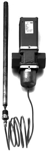
V47N Series Reverse Acting Valve
Selection Charts
V47N Series Reverse Acting Valve
1. Refer to sizing information in V47 Series Temperature Actuated Modulating Valve (LIT-1927330), then specify the code number from this chart.
Repair Parts and Accessories
| Parts For: | Product Code Number | ||
| Seat Repair Kit | Replacement Sensing | Bulb Well Number | |
| V47NB-1C | STT15A-602R | — | WEL18A-602R (Brass) |
| V47NC-1C | STT16A-601R | ||
| V47NR-1C | STT17A-610R | SET29A-605R | — |
Valves and Valve Accessories Code No. LIT-1927345
 V48 Series Three-Way Water Regulating Valve
![]()
![]()
![]()
Description
V48 Series valves are designed specifically for condensing units cooled either by atmospheric or forced draft cooling towers.
Refer to the V48 Series 3-Way Water Regulating Valves for Cooling Tower Systems Product Bulletin (LIT-121705) for important product application information.
Applications
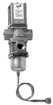 V48 Series valves are used on single or multiple condenser hook-ups to the tower to provide the most economical and efficient use of the tower.
Repair Information
If the V48 Series Three-Way Water Regulating Valve fails to operate within its specifications, replace the unit. For a replacement valve, contact the nearest Johnson Controls® representative.
Selection Chart (Non-Corrosive Refrigerants)
V48 Series Three-Way Water Regulating Valve
| Product
Code Number |
Pipe
Size, In. |
Range Opening Point
of |
Pressure
Element Style |
Water
Supply Pressure |
Inlet
and Outlet Ports |
Max
Bellows Overpressure |
Seat Repair
Kit |
Replacement
Sensing Element |
| V48AB-1C | 1/2 | 85 to 110 | 30 in. capillary
with 1/4 in. flare nut (Style 45)1 |
150 psig
(1,034 kPa) |
Threaded | 230 psig
(1,586 kPa) |
STT15A-605R | SEP91A-602R SEC99AA-36C2 |
| V48AB-2C | 1/2 | 145 to 190 | 320 psig
(2,206 kPa) |
|||||
| V48AC-1C | 3/4 | 85 to 110 | 230 psig
(1,586 kPa) |
STT16A-604R | SEP91A-601R SEC99AA-36C2 | |||
| V48AC-2C | 3/4 | 145 to 190 | 320 psig
(2,206 kPa) |
|||||
| V48AD-1C | 1 | 85 to 110 | 230 psig
(1,586 kPa) |
STT17A-616R | SEP91A-603R SEC99AA-36C2 | |||
| V48AD-2C | 1 | 145 to 190 | 320 psig
(2,206 kPa) |
|||||
| V48AE-1C | 1-1/4 | 85 to 110 | 230 psig
(1,586 kPa) |
STT17A-617R | ||||
| V48AE-2C | 1-1/4 | 145 to 190 | 320 psig
(2,206 kPa) |
|||||
| V48AF-1C | 1-1/2 | 85 to 110 | 1/4 in. External Flare
Fitting (Style 5) |
230 psig
(1,586 kPa) |
STT17A-604R | SEP81A-602R | ||
| V48AF-2C | 1-1/2 | 145 to 190 | 320 psig
(2,206 kPa) |
SEP81A-601R | ||||
| V48AJ-2C | 1/2 | 30 in. capillary | Union | 320 psig
(2,206 kPa) |
STT15A-605R | SEP77A-605R | ||
| V48EK-2C | 3/4 | 30 in. capillary | 370 psig
(2,551 kPa) |
STT16A-604R | SEP127A-600R | |||
| V48AL-2C | 1 | 320 psig
(2,206 kPa) |
STT17A-616R | SEP107A-602R | ||||
| V48AM-2C | 1-1/4 | STT17A-617R |
- Standard capillary length on Style 45 elements is 30 inches
- Replacement element supplied with 1/4 in. external SAE connector. Order SEC99AA capillary kit with two flare nuts separately if needed. Use only on valves specified.
Technical Specifications
V48 Series Factory Settings
| Refrigerant (R) | Factory Settings psig (kPa) | |
| Opening Press.
Port 1 to Port 2 |
Closing Press.
Port 1 to Port 3 |
|
| Low Pressure (R-12, R134a, etc.) | 95 (655) | 120 (896) |
| Medium Pressure (R-22, R404A, etc.) | 165 (1,138) | 215 (1,482) |
Valves and Valve Accessories Code No. LIT-1900163
 V146 Series Two-Way Pressure-Actuated Water-Regulating Valves
![]()
![]()
![]()
Description
The V146 Series Two-Way Pressure- Actuated Water-Regulating Valves regulate water flow to control refrigerant head pressure in systems with water-cooled condensers. The V146 valves are ideal for applications with system water pressures of up to 350 psig (24.1 bar), such as high-rise buildings.
V146EK and V146AL valves have an adjustable opening point in a refrigerant pressure range of 70 to 260 psi (4.8 to
17.9 bar). V146EK and V146AL valves are available in a 3/4 in. and 1 in. size. Use these valves with standard, non-corrosive refrigerants.
V146GK1 and V146GL1 valves have an adjustable opening point in a refrigerant pressure range of 200 to 400 psi (13.8 to
27.6 bar). The V146GK1 and V146GL1 valves are available in 3/4 in. and 1 in. size for use with standard, non-corrosive, high-pressure refrigerants.
Refer to the V146 Series 2-Way
Pressure-Actuated Water-Regulating Valves Product Bulletin (LIT-121709) for important product application information.
Features
• no close-fitting or sliding parts in water passages
• high-pressure design
• pressure-balanced design
• corrosion-resistant material for internal parts
• accessible range spring
• take-apart construction
Applications
Each application is unique and requires specific engineering data to properly size and design a system to fulfill the appropriate requirements. Typically, a valve is replaced with another valve of the same size in a properly sized and engineered system.
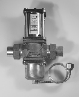
V146 Series Valve
![]()
![]()
![]()
![]()
![]()
![]()
![]()
![]()
![]()
![]()
![]()
A
B
D
C
Port 1
Port 2
E
Pressure connection and capillary
as specified
3/4 in. V146EK Valves
High Refrigerant Pressure 3/4 in. V146GK1 Valves
![]()
![]()
![]()
![]()
![]()
![]()
![]()
![]()
![]()
![]()
![]()
![]()
A
B
D
C
Port 1
Port 2
E
FIG:V146_rnddim
FIG:V146GK_dim
Valves and Valve Accessories
![]() V146 Series Two-Way Pressure-Actuated Water-Regulating Valves (Continued)
V146 Series Two-Way Pressure-Actuated Water-Regulating Valves (Continued)
![]()
![]()
![]()
Valve Dimensions, Inches (Millimeters)
| Product Code
Number |
Nominal Valve
Size |
A | B | C | D | E |
| V146EK-1C | 3/4 in. | 3-3/8 (86) | 2-3/16 (55) | 7-3/16 (183) | 4-3/16 (106) | 3 (76) |
| V146GK1-001C | 3/4 in. | 3-3/8 (86) | 2-3/16 (55) | 8 (204) | 4-3/16 (106) | 3-13/16 (98) |
| V146AL-1C | 1 in. | 4-3/4 (121) | 2-13/16 (72) | 10 (254) | 5-15/16 (151) | 4-1/16 (103) |
| V146GL1-001C | 1 in. | 4-3/4 (121) | 2-13/16 (72) | 10-1/2 (267) | 5-15/16 (151) | 4-9/16 (116) |
![]()
![]()
![]()
![]()
![]()
![]()
![]()
![]()
![]()

![]()
![]()
![]()
A
B
D
C
Port 1
Port 2
E
![]()
![]()
![]()
![]()
![]()
![]()
![]()
![]()
![]()
![]()
![]()
![]()
![]()
A
B
D
C
Port 1
Port 2
E
Pressure connection and capillary as specified.
FIG:V146AL_dim
FIG:V146GL_dim
1 in. V146AL Valves
High Refrigerant Pressure 1 in. V146GL1 Valves
Selection
To make a rough field estimate of the size of valve for an application, find the valve size by locating a point on a flow chart that satisfies these requirements:
• water flow required by the condenser (Flow)
• refrigerant head pressure rise (PRISE)
• available water pressure (PAVAIL)
Follow these steps, and use the information obtained to locate a point on one of the flowcharts that satisfies all three steps.
- Take the water flow required by the condenser (Flow) from information provided by the manufacturer of the condensing unit. If the manufacturer’s information is unavailable, use the following information to make a rough approximation of maximum water flow in gallons per minute (gpm) (cubic meters per hour [m3/hr]):
• System Capacity (Tons of Refrigeration)
• Outlet Water Temperature (Temp. Outlet)
• Inlet Water Temperature (Temp. Inlet)
Calculate the flow using the following formula:
Flow = Tons of Refrigeration x 30 (Temp.Outlet – Temp.Inlet )
FIG:flw_eqn
Flow Required
Note: If the outlet temperature is unknown, assume it to be 10F (5.6C) above the inlet temperature.
- Determine refrigerant head pressure rise above the valve opening point (PRISE) using the following steps:
- The Valve Closing Pressure (PCLOSE) is equal to the refrigerant pressure at the highest ambient temperature the refrigeration equipment experiences in the Off cycle. Use a
Pressure-Temperature Chart for the refrigerant selected to find this pressure.
-
- To approximate the Valve Opening Pressure (POPEN), add about 7 psi (0.5 bar) for EK and AL models or 10 psi (0.7 bar) for GL1 or GK1 models to the Valve Closing Pressure.
Valves and Valve Accessories
![]() V146 Series Two-Way Pressure-Actuated Water-Regulating Valves (Continued)
V146 Series Two-Way Pressure-Actuated Water-Regulating Valves (Continued)
![]()
![]()
![]()
POPEN = PCLOSE +7 psi (0.5 bar)
P = P +10 psi (0.7 bar)
FIG:V14x_eqn_opn_prssr
The maximum recommended differential water pressure across a valve is 60 psi (4.1 bar).
Flow (gpm)
45
| Pressure Drop Through Valve (psi) | |||||||||
OPEN CLOSE
Valve Opening Pressure, EK and AL Models (Top) or GK1 and GL1 Models (Bottom)
-
- From the Pressure-Temperature Chart for the refrigerant selected, read the Refrigerant Condensing Pressure (PCOND) (operating head pressure) corresponding to the selected
condensing temperature.
-
- Subtract the Valve Opening Pressure from the Refrigerant Condensing Pressure. This gives the head pressure rise.
FIG:eqn_hd_prssr_rs
PRISE = PCOND – POPEN
40
35
30
25
20
15
10
5
010 15 20 25
30 35
40 45 50
60
50
40
30
20
10
FIG:V146EK_chrt
55 60
Figure 1: Refrigerant Head Pressure Rise
- Determine the available water pressure to the valve (PAVAIL) using the following steps. This is the actual water pressure available to force water through the valve.
- Determine the minimum inlet pressure (PIN). This is the water pressure from city water mains, pumps, or other sources.
- Pressure drop through condenser (PCOND) is the difference in water pressure between the condenser inlet and the condenser outlet. Obtain this information from the condenser manufacturer.
- Estimate or calculate the pressure drop through all associated piping (PLOSS).
- Subtract the PCOND and PLOSS from PIN. The result is PAVAIL.
Flow (gpm)
75
70
65
60
55
50
45
40
35
30
25
20
15
10
5
0
![]()
Cooling Tower
Pump
P2
P1
2-Way Valve
oss 2
P
Loss
Condenser
FIG:2wy_prss_drp
FIG:V146AL_chrt
Refrigerant Head Pressure Rise (psi)
3/4 in. V146EK Valve
60
| Pressure Drop Through Valve (psi) | |||||||||
50
40
30
20
10
10 15 20 25 30 35 40 45 50 55 60
P Refrigerant Head Pressure Rise (psi)
IN
1 in. V146AL Valve
P
![]() L 1
L 1
| PCOND = P1 – P2 | + P + …
P = PLoss 1 Loss 2 LOSS |
|
| PAVAIL = PIN – ( PCOND + PLOSS) | ||
![]() Available Water Pressure
Available Water Pressure
- Select the proper valve size from the flowcharts by locating a point on a chart that satisfies the flow, the head pressure rise above opening point, and the pressure drop across the valve.
Use these equations to convert between U.S. and S.I. units.
• 1 dm3/s = 3.6 m3/h = 15.9 U.S. gal. /min. = 13.2 U.K. gal. /min.
• 1 bar = 100 kPa = 0.1 MPa 1.02 kg/cm2 = 0.987 atm 14.5 psi
Valves and Valve Accessories
![]() V146 Series Two-Way Pressure-Actuated Water-Regulating Valves (Continued)
V146 Series Two-Way Pressure-Actuated Water-Regulating Valves (Continued)
![]()
![]()
![]()
Refrigerant Head Pressure Rise (bar)
0.7
Flow
10 (0.7)
Pressure Drop Through Valve, psi (bar)
5 (0.3)
2 (0.1)
60 (4.1)
50 (3.4)
40 (2.8)
30 (2.1)
25 (1.7)
20 (1.4)
1.7
2.7
3.7
4.7
5.7
6.7
Flow
(GPM)
45
40
35
30
25
20
15
10
5
(m3/hr) 10
8
6
4
2
0
10 20 30 40
50 60 70 80
0
90 100
FIG:V146GK1_chrt
Refrigerant Head Pressure Rise (psig)
High Refrigerant Pressure 3/4 in. V146GK1 Valves
Flow GPM
70
60
50
40
30
20
10
Refrigerant Head Pressure Rise (bar)
Flow m3/hr
![]()
1.3
2.3
3.3
4.3
5.3
6.3
7.3
60 (4.1)
50 (3.4)
40 (2.8)
30 (2.1)
25 (1.7)
20 (1.4)
10 (1.0)
5 (0.3)
2 (0.1)
Pressure Drop Through Valve psig (m3/hr)
16.2
14.2
12.2
10.2
8.2
6.2
4.2
2.2
0
10 20 30 40 50 60 70 80 90
Refrigerant Head Pressure Rise (psig)
0.2
High Refrigerant Pressure 1 in. V146GL1 Valves
FIG:V146GL_chrt
Valves and Valve Accessories
![]() V146 Series Two-Way Pressure-Actuated Water-Regulating Valves (Continued)
V146 Series Two-Way Pressure-Actuated Water-Regulating Valves (Continued)
![]()
![]()
![]()
Style 5 Style 46
![]()
![]()
![]()
1/4-in. SAE External Flare Connector
Copper Capillary with
1/4-in. SAE Internal Flare Connector (Includes Valve Stem Depressor)
Pressure Connection Styles
Selection Chart
| Product Code Number | Nominal Valve Size | Inlet and Outlet Ports | Pressure Connection
Style |
Shipping Weight, lb (kg) |
| V146EK-1C | 3/4 in. | Union (Sweat) | 46 | 4.3 (2.0) |
| V146GK1-001C | 3/4 in. | Union (Sweat) | 5 | 4.3 (2.0) |
| V146AL-1C | 1 in. | Union (Sweat) | 46 | 9.3 (4.0) |
| V146GL1-001C | 1 in. | Union (Sweat) | 5 | 9.3 (4.0) |
Repair Information
If the V146 Series Two-Way Pressure-Actuated Water-Regulating Valve fails to operate within its specifications, refer to the V146 Series Two-Way Pressure-Actuated Water-Regulating Valves Product Bulletin (LIT-1201709) for a list of repair parts available.
Technical Specifications
| V146 Series 2-Way Pressure-Actuated Water-Regulating Valves | |
| Maximum Refrigerant Pressure | V146EK: 370 psi (25.5 bar)
V146AL: 320 psi (22.1 bar) |
| Maximum Working Pressure | V146GK1, V146GL1: 630 psi (43.4 bar) |
| Opening Point Adjustment Range | V146EK, V146AL: 70 to 260 psi (4.8 to 17.9 bar)
V146GK1, V146GL1: 200 to 400 psi (13.8 to 27.6 bar) |
| Factory-Set Opening Point | V146EK, V146AL: 165 psi (11.4 bar)
V146GK1, V146GL1: 275 psi (19.0 bar) |
| Media | 350 psi (24.1 bar) maximum,
-4F to 170F (-20C to 77C) glycol/water or liquids with low freezing points that are compatible with valve materials |
Valves and Valve Accessories Code No. LIT-1900164
![]() V148 Series Three-Way Pressure-Actuated Water-Regulating Valves
V148 Series Three-Way Pressure-Actuated Water-Regulating Valves
![]()
![]()
![]()
Description
The V148 Series Three-Way
Pressure-Actuated Water-Regulating Valves regulate water flow to control refrigerant head pressure in systems with single or multiple water-cooled condensers. The V148 valves are designed for applications with system water pressures of up to 350 psi (24.1 bar), such as high-rise buildings.
V148EK and V148AL valves have an adjustable opening point in a refrigerant pressure range of 145 to 190 psi (10.0 to
13.1 bar). V148EK and V148AL valves are available in 3/4 in. and 1 in. sizes. Use these valves with standard, non-corrosive refrigerants.
V148GK1 and V148GL1 valves have an adjustable opening point in a refrigerant pressure range of 200 to 400 psi (13.8 to
-
- bar). The V148GK1 and V148GL1 Valves are available in 3/4 in. and 1 in. sizes for use with standard, non-corrosive,
high-pressure refrigerants.
Refer to the V148 Series 3-Way
Pressure-Actuated Water-Regulating Valves Product Bulletin (LIT-121712) for important product application information.
Features
• no close-fitting or sliding parts in water passages
• high water pressure design
• pressure-balanced design
• corrosion-resistant material for internal parts
• accessible range spring
• take-apart construction
Applications
Each application is unique and requires specific engineering data to properly size and design a system to fulfill the appropriate requirements. Typically, a valve is replaced with another valve of the same size in a properly sized and engineered system.
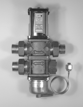
V148 Series Valve
![]()
![]()
![]()
![]()
![]()
![]()
![]()
![]()
![]()
![]()
![]()

![]()
![]()
![]()
![]()
![]()
A
B
C
Port 1
Port 2
D
E
Port 3
Plugged
F
Pressure connection and capillary as specified
![]()
![]()
![]()
![]()
![]()
![]()
![]()
![]()
![]()
![]()
![]()
![]()
![]()
![]()
![]()
A
B
C
Port 1
Port 2
D
E
Port 3
Plugged
F
Pressure connection and capillary as specified
3/4 in. V148EK Valve 1 in. V148AL Valve
FIG:V148EK_075_dim
FIG:V148AL_100_dim
Valves and Valve Accessories
![]() V148 Series Three-Way Pressure-Actuated Water-Regulating Valves (Continued)
V148 Series Three-Way Pressure-Actuated Water-Regulating Valves (Continued)
![]()
![]()
![]()
Valve Dimensions, Inches (Millimeters)
| Model | Nominal
Valve Size |
A | B | C | D | E | F |
| V148EK-1C | 3/4 in. | 3-3/8 (86) | 2-3/16 (56) | 9 (229) | 4-3/16 (106) | 1-3/4 (44) | 3 (76) |
| V148GK1-001C | 3/4 in. | 3-3/8 (86) | 2-3/16 (56) | 9-13/16 (249) | 4-3/16 (106) | 1-3/4 (44) | 3-13/16 (97) |
| V148AL-1C | 1 in. | 4-3/4 (121) | 2-3/4 (71) | 12 (305) | 5-15/16 (151) | 2 (51) | 4 (102) |
| V148GL1-001C | 1 in. | 4-3/4 (121) | 2-3/4 (71) | 12-1/2 (318) | 5-15/16 (151) | 2 (51) | 4-1/2 (115) |
3/4 in. High Refrigerant Pressure V148GK1 Valves
![]()
![]()
![]()
![]()
![]()
![]()
![]()
![]()
![]()
![]()
![]()
![]()
![]()
![]()
![]()
![]()
![]()
A
B
C
Port 1
Port 2
D
Port 3
Plugged
F
E
![]()
![]()
![]()
![]()
![]()
![]()
![]()
![]()
![]()
![]()
![]()
![]()
![]()
![]()
![]()
![]()
A
B
C
Port 1
Port 2
D
E
Port 3
Plugged
F
FIG:V148GK1_075_dim
FIG:V148GL1_100_dim
1 in. High Refrigerant Pressure V148GL1 Valves
Selection
To make a rough field estimate of the size of valve for an application, find the valve size by locating a point on a flow chart that satisfies these requirements:
• water flow required by the condenser (Flow)
• refrigerant head pressure rise (PRISE)
• available water pressure (PAVAIL)
Follow these steps, and use the information obtained to locate a point on one of the flowcharts that satisfies all three steps.
- Take the water flow required by the condenser (Flow) from information provided by the manufacturer of the condensing unit. If the manufacturer’s information is unavailable, use the following information to make a rough approximation of maximum water flow in gallons per minute (gpm) (cubic meters per hour [m3/hr]):
• System Capacity (Tons of Refrigeration)
• Outlet Water Temperature (Temp. Outlet)
• Inlet Water Temperature (Temp. Inlet)
Calculate the flow using the following formula:
Flow = Tons of Refrigeration x 30 (Temp.Outlet – Temp.Inlet )
FIG:flw_eqn
Flow Required
Note: If the outlet temperature is unknown, assume it to be 10F (5.6C) above the inlet temperature.
- Determine refrigerant head pressure rise above the valve opening point (PRISE) using the following steps:
- The Valve Closing Pressure (PCLOSE) is equal to the refrigerant pressure at the highest ambient temperature the
refrigeration equipment experiences in the Off cycle. Use a Pressure-Temperature Chart for the refrigerant selected to find this pressure.
-
- To approximate the Valve Opening Pressure (POPEN), add about 7 psi (0.5 bar) for EK and AL models or 10 psi (0.7 bar) for GK1 and GL1 models to the Valve Closing Pressure.
Valves and Valve Accessories
![]() V148 Series Three-Way Pressure-Actuated Water-Regulating Valves (Continued)
V148 Series Three-Way Pressure-Actuated Water-Regulating Valves (Continued)
![]()
![]()
![]()
POPEN = PCLOSE +7 psi (0.5 bar) POPEN = PCLOSE +10 psi (0.7 bar)
FIG:V14x_eqn_opn_prssr
Valve Opening Pressure, EK and AL Models (Top) or GK1 and GL1 Models (Bottom)
-
- From the Pressure-Temperature Chart for the refrigerant
Use these equations to convert between U.S. and S.I. units.
- 1 dm3/s = 3.6 m3/h = 15.9 U.S. gal. /min. = 13.2 U.K. gal. /min.
- 1 bar = 100 kPa = 0.1 MPa 1.02 kg/cm2 = 0.987 atm 14.5 psi
Flow (gpm)
| Pressure Drop Through Valve | (psi) | ||||||||
selected, read the Refrigerant Condensing Pressure (PCOND) 30 30
(operating head pressure) corresponding to the selected
condensing temperature. 25 20
-
- Subtract the Valve Opening Pressure from the Refrigerant
Condensing Pressure. This gives the head pressure rise. 20 15
10
FIG:eqn_hd_prssr_rs
15
7
PRISE = PCOND – POPEN
10
FIG:V148EK_chrt
Refrigerant Head Pressure Rise
- Determine the available water pressure to the valve (PAVAIL) using the following steps. This is the actual water pressure available to force water through the valve.
- Determine the minimum inlet pressure (PIN). This is the water pressure from city water mains, pumps, or other sources.
- Pressure drop through condenser (PCOND) is the difference in water pressure between the condenser inlet and the condenser outlet. Obtain this information from the condenser manufacturer.
- Estimate or calculate the pressure drop through all associated
5
0
Flow
10 15 20 25 30 35 40 45 50 55 60
Refrigerant Head Pressure Rise (psi)
3/4 in. V148EK Valve
piping (PLOSS).
-
- Subtract the PCOND and PLOSS from PIN. The result is PAVAIL.
![]()
![]()
FIG:3wy_prss_drp
Cooling Tower
Pump
P
IN
3-Way
(gpm)
55 30
| Pressure Drop Through Valve (psi) | |||||||||
50
45 20
40 15
35
30 10
25 7
20
15
FIG:V148AL_chrt
Valve
P2 P1 10
Condenser
P P 5
Loss 2
![]()
Loss 1
Balancing Valve Bypass Line
P
=
LOSS
P
Loss 1 Loss 2
+ P
+ …
PCOND = P1 – P2
0
10 15 20 25 30 35 40 45 50 55 60
Refrigerant Head Pressure Rise (psi)
1 in. V148AL Valve
![]()
PAVAIL= PIN – ( PCOND + PLOSS)
Available Water Pressure
- Select the proper valve size from the flowcharts by locating a point on a chart that satisfies the flow, the head pressure rise above opening point, and the pressure drop across the valve.
Valves and Valve Accessories
![]() V148 Series Three-Way Pressure-Actuated Water-Regulating Valves (Continued)
V148 Series Three-Way Pressure-Actuated Water-Regulating Valves (Continued)
![]()
![]()
![]()
Flow (GPM)
45
40
35
30
25
20
15
10
5
Refrigerant Head Pressure Rise (bar)
0.7 1.7 2.7 3.7 4.7 5.7 6.7
Flow (m3/hr)
60 (4.1)
50 (3.4)
Pressure Drop Through Valve psi (bar)
40 (2.8)
30 (2.1)
25 (1.7)
20 (1.4)
10 (0.7)
5 (0.3)
2 (0.1)
10
8
6
4
2
0 0
10 20 30 40 50 60 70 80 90 100
FIG:V148GK1
Refrigerant Head Pressure Rise (psig)
High Refrigerant Pressure 3/4 in. V148GK1 Valve
Flow GPM
70
60
Refrigerant Head Pressure Rise (bar)
1.3 2.3 3.3 4.3 5.3 6.3 7.3
![]()
60 (4.1)
50 (3.4)
40 (2.8)
Flow m3/hr 16.2
14.2
30 (2.1)
50 25 (1.7)
20 (1.4)
40
10 (1.0)
30
5 (0.3)
20
2 (0.1)
10
Pressure Drop Through Valve psig (m3/hr)
0
10 20 30 40 50 60 70 80 90 100 110
FIG:V148GL_chrt
Refrigerant Head Pressure Rise (psig)
12.2
10.2
8.2
6.2
4.2
2.2
0.2
High Refrigerant Pressure 1 in. V148GL1 Valve
Valves and Valve Accessories
![]() V148 Series Three-Way Pressure-Actuated Water-Regulating Valves (Continued)
V148 Series Three-Way Pressure-Actuated Water-Regulating Valves (Continued)
![]()
![]()
![]()
![]()

Style 5
Style 46
Copper Capillary with
1/4-in. SAE External Flare Connector 1/4-in. SAE Internal Flare Connector
(Includes Valve Stem Depressor)
Pressure Connection Styles
Selection Chart
| Product Code Number | Nominal Valve
Size |
Inlet and Outlet Ports | Pressure Connection Style | Shipping Weight, lb (kg) |
| V148EK-1C | 3/4 in. | Union (Sweat) | 46 | 7 (3.2) |
| V148GK1-001C | 3/4 in. | Union (Sweat) | 5 | 7 (3.2) |
| V148AL-1C | 1 in. | Union (Sweat) | 46 | 12 (5.4) |
| V148GL1-001C | 1 in. | Union (Sweat) | 5 | 12 (5.4) |
Repair Information
If the V148 Series Three-Way Pressure-Actuated Water-Regulating Valve fails to operate within its specifications, refer to the V148 Series Three-Way Pressure-Actuated Water-Regulating Valves Product Bulletin (LIT-121712) for a list of repair parts available.
Technical Specifications
| V148 Series 3-Way Pressure-Actuated Water-Regulating Valves | |
| Maximum Refrigerant Pressure | V148EK: 370 psig (25.5 bar)
V148AL: 320 psig (22.1 bar) |
| Maximum Working Pressure | V148GK1, V148GL1: 630 psig (43.4 bar) |
| Factory-Set Opening Point (Port 1 to Port 2) | V148EK, V148AL: 165 psig (11.4 bar)
V148GK1, V148GL1: 275 psig (19.0 bar) |
| Opening Point Adjustment Range (Port 1 to Port 2) | V148EK, V148AL: 145 to 190 psi (10.0 to 13.1 bar)
V148GK1, V148GL1: 200 to 400 psi (13.8 to 27.6 bar) |
| Throttling Range | V148EK, V148AL: 70 psig (4.8 bar)
V148GK1, V148GL1: 100 psig (6.9 bar) |
| Media | 350 psi (24.1 bar) maximum,
-4F to 170F (-20C to 77C) glycol/water or liquids with low freezing points that are compatible with valve materials |
Valves and Valve Accessories Code No. LIT-1900575
 V246 Series Two-Way Pressure-Actuated Water-Regulating Valves for High-Pressure Refrigerants
![]()
![]()
![]()
Description
The V246 Series Two-Way
Pressure-Actuated Water-Regulating Valves for High-Pressure Refrigerants come in two types of control action: direct acting and reverse acting. V246 valves regulate water flow to control refrigerant head pressure in systems with water-cooled condensers.
The V246 Series Valves are available in 3/8 in. through 2 in. sizes and have a maximum allowable water pressure of 150 psig
(10.3 bar). Direct acting V246 valves have an adjustable opening point in a refrigerant pressure range of 200 to 400 psi
(13.8 to 27.6 bar), and reverse acting valves have a range of 135 to 300 psi
(9.3 to 20.7 bar). V246 valves may be used with standard non-corrosive refrigerants.
Maritime models, which have nickel copper (Monel®) internal parts, are available for applications where the media may be corrosive to the internal parts.
Selection Charts
Refer to the V246 Series 2-Way
Pressure-Actuated Water-Regulating Valves for High-Pressure Refrigerants Product Bulletin (LIT-12011514) for important product application information.
Features
• no close fitting or sliding parts in water passages
• accessible range spring
• take-apart construction
• pressure-balanced design
• corrosion-resistant material for internal parts
Repair Information
If the V246 Series Two-Way
Pressure-Actuated Water-Regulating Valve for High Pressure Refrigerants fails to operate within its specifications, refer to the V246 Series Two-Way Pressure-Actuated
Water-Regulating Valves for High Pressure Refrigerants Product Bulletin (LIT-12011514) for a list of repair parts available.
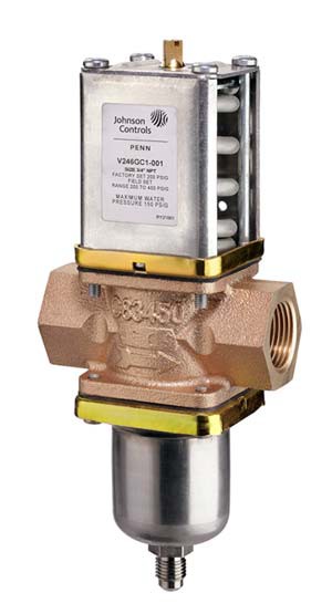
V246 Series Water-Regulating Valve
North American Standard Production Models
| Product Code Number | Construction | Valve Size and Connection | Element Style | Shipping Weight,
lb (kg) |
| V246GA1-001C | Direct Acting1, Commercial | 3/8 in. NPT Screw | Style 5 | 1.8 (0.8) |
| V246GB1-001C | Direct Acting1, Commercial | 1/2 in. NPT Screw | Style 5 | 3.0 (1.4) |
| V246GC1-001C | Direct Acting1, Commercial | 3/4 in. NPT Screw | Style 5 | 3.7 (1.7) |
| V246GD1-001C | Direct Acting1, Commercial | 1 in. NPT Screw | Style 5 | 9.3 (4.2) |
| V246GE1-001C | Direct Acting1, Commercial | 1-1/4 in. NPT Screw | Style 5 | 10 (4.5) |
| V246GM1-001C | Direct Acting1, Commercial | 1-1/4 in. Union Sweat | Style 5 | 10 (4.5) |
| V246GR1-001C | Direct Acting1, Commercial | 1-1/2 in. Flange | Style 5 | 13.6 (6.2) |
| V246GS1-001C | Direct Acting1, Commercial | 2 in. Flange | Style 5 | 27 (12.3) |
| V246HA1-001C | Direct Acting1, Maritime | 3/8 in. NPT Screw | Style 5 | 1.8 (0.8) |
| V246HB1-001C | Direct Acting1, Maritime | 1/2 in. NPT Screw | Style 5 | 3.0 (1.4) |
| V246HC1-001C | Direct Acting1, Maritime | 3/4 in. NPT Screw | Style 5 | 4.3 (2.0) |
| V246HD1-001C | Direct Acting1, Maritime | 1 in. NPT Screw | Style 5 | 9.5 (4.3) |
| V246HE1-001C | Direct Acting1, Maritime | 1-1/4 in. NPT Screw | Style 5 | 10.3 (4.7) |
| V246HR1-001C | Direct Acting1, Maritime | 1-1/2 in. ASME Flange | Style 5 | 13.6 (6.2) |
| V246HS1-001C | Direct Acting1, Maritime | 2 in. ASME Flange | Style 5 | 27 (12.3) |
| V246KA1-001C | Direct Acting1, Commercial, Low Flow | 3/8 in. NPT Screw | Style 5 | 1.8 (0.8) |
| V246NA1-001C | Reverse Acting2, Commercial | 3/8 in. NPT Screw | Style 5 | 1.8 (0.8) |
| V246NB1-001C | Reverse Acting2, Commercial | 1/2 in. NPT Screw | Style 5 | 3.0 (1.4) |
| V246NC1-001C | Reverse Acting2, Commercial | 3/4 in. NPT Screw | Style 5 | 3.7 (1.7) |
| V246ND1-001C | Reverse Acting2, Commercial | 1 in. NPT Screw | Style 5 | 9.3 (4.2) |
European Standard Production Models (Part 1 of 2)
| Product Code Number | Construction | Valve Size and Connection | Element Style | Shipping Weight,
kg (lb) |
| V246GA1A001C | Direct Acting, Commercial | 3/8 in. BSPP Screw, ISO 228 | Style 5 | 0.8 (1.8) |
| V246GB1A001C | Direct Acting, Commercial | 1/2 in. BSPP Screw, ISO 228 | Style 5 | 1.4 (3.0) |
| V246GC1A001C | Direct Acting, Commercial | 3/4 in. BSPP Screw, ISO 228 | Style 5 | 1.7 (3.7) |
| V246GD1B001C | Direct Acting, Commercial | 1 in. BSPT Screw, ISO 7 | Style 5 | 4.2 (9.3) |
| V246GE1B001C | Direct Acting, Commercial | 1-1/4 in. BSPT Screw, ISO 7 | Style 5 | 4.5 (10) |
Valves and Valve Accessories
![]() V246 Series Two-Way Pressure-Actuated Water-Regulating Valves for High-Pressure Refrigerants (Continued)
V246 Series Two-Way Pressure-Actuated Water-Regulating Valves for High-Pressure Refrigerants (Continued)
![]()
![]()
![]()
European Standard Production Models (Part 2 of 2)
| Product Code Number | Construction | Valve Size and Connection | Element Style | Shipping Weight,
kg (lb) |
| V246GR1B001C | Direct Acting, Commercial | 1-1/2 in. Flange, DIN2533 | Style 5 | 6.2 (13.6) |
| V246GS1B001C | Direct Acting, Commercial | 2 in. Flange, DIN2533 | Style 5 | 12.3 (27) |
| V246HA1B001C | Direct Acting, Maritime | 3/8 in. BSPP Screw, ISO 228 | Style 5 | 0.8 (1.8) |
| V246HB1B001C | Direct Acting, Maritime | 1/2 in. BSPP Screw, ISO 228 | Style 5 | 1.4 (3.0) |
| V246HC1B001C | Direct Acting, Maritime | 3/4 in. BSPP Screw, ISO 228 | Style 5 | 2.0 (4.3) |
| V246HD1B001C | Direct Acting, Maritime | 1 in. BSPP Screw, ISO 228 | Style 5 | 4.3 (9.5) |
| V246HE1B001C | Direct Acting, Maritime | 1-1/4 in. BSPP Screw, ISO 228 | Style 5 | 4.7 (10.3) |
| V246HR1B001C | Direct Acting, Maritime | 1-1/2 in. Flange, DIN86021 | Style 5 | 6.2 (13.6) |
| V246HS1B001C | Direct Acting, Maritime | 2 in. Flange, DIN86021 | Style 5 | 12.3 (27) |
Valve Sizing Information
Each application is unique and requires specific engineering data to properly size and design a system to fulfill the appropriate requirements. Typically, a valve is replaced with another valve of the same size in a properly sized and engineered system. In North America, contact Johnson Controls/PENN® Refrigeration Application Engineering at 1-800-275-5676 to obtain specific engineering data. In other areas, contact the local Johnson Controls® sales office to obtain specific engineering data.
To make a rough field estimate of the size of valve for an application, find the valve size needed by locating a point on a flow chart that satisfies these requirements:
• water flow required by the condenser (Flow)
• refrigerant head pressure rise (PRISE)
• available water pressure (PAVAIL)
Follow these steps, and use the information obtained to locate a point on one of the flowcharts that satisfies all three steps.
1. Take the water flow required by the condenser (Flow) from information provided by the manufacturer of the condensing unit. If the manufacturer’s information is unavailable, use the following information to make a rough approximation of water flow in gallons per minute (gpm) [cubic meters per hour (m3/hr)]:
• System Capacity (Tons of Refrigeration)
• Outlet Water Temperature (Temp. Outlet)
• Inlet Water Temperature (Temp. Inlet) Calculate the flow using the following formula:
Tons of Refrigeration x 30
.
POPEN = PCLOSE +10 psi (0.7 bar)
FIG:eqn_opn_pr
Valve Opening Pressure
-
- From the Pressure-Temperature Chart for the refrigerant selected, read the Refrigerant Condensing Pressure (PCOND) (operating head pressure) corresponding to the selected
condensing temperature.
-
- Subtract the Valve Opening Pressure from the Refrigerant Condensing Pressure. This gives the head pressure rise.
FIG:eqn_hd_prssr_rs
PRISE = PCOND – POPEN
Refrigerant Head Pressure Rise
- Determine the available water pressure to the valve (PAVAIL) using the following steps. This is the actual water pressure available to force water through the valve.
- Determine the inlet pressure (PIN). This is the water pressure from city water mains, pumps, or other sources.
- Pressure drop through condenser (PCOND) is the difference in water pressure between the condenser inlet and the condenser outlet. Obtain this information from the condenser manufacturer.
- Estimate or calculate the pressure drop through all associated piping (PLOSS).
- Subtract the PCOND and PLOSS from PIN. The result is PAVAIL.
FIG:2wy_prss_drp
Flow =
(Temp.Outlet – Temp.Inlet)
![]()
Pump
P2
2-Way Valve
Condenser
P1
oss 2
P
Loss
Cooling Tower
FIG:flw_eqn
P
IN
Flow Required
Note: If the outlet temperature is unknown, assume it to be 10F (6C) above the inlet temperature.
- Determine refrigerant head pressure rise above the valve opening point (PRISE) using the Refrigerant Head Pressure Rise figure and the following steps:
- The Valve Closing Pressure (PCLOSE) is equal to the refrigerant pressure at the highest ambient temperature the refrigeration equipment experiences in the Off cycle. Use a
Pressure-Temperature Chart for the refrigerant selected to find this pressure.
-
- To approximate the Valve Opening Pressure (POPEN), add about 10 psi (0.7 bar) to the Valve Closing Pressure.
Note: Add about 20 psi (1.4 bar) for 3/8 in. valves.
P
![]() L 1
L 1
| PCOND= P1 – P2 | P = P + P + …
LOSS Loss 1 Loss 2 |
|
| PAVAIL= PIN – ( PCOND + PLOSS) | ||
![]() Available Water Pressure
Available Water Pressure
4. Select the proper valve size from the flowcharts by locating a point on a chart that satisfies the flow, the head pressure rise above opening point, and the pressure drop across the valve.
Metric Conversions
Use these equations to convert between U.S. and S.I. units.
• 1 dm3/s = 3.6 m3/h = 15.9 U.S. gal. /min. = 13.2 U.K. gal. /min.
• 1 bar = 100 kPa = 0.1 MPa 1.02 kg/cm2 = 0.987 atm 14.5 psi
Valves and Valve Accessories
![]() V246 Series Two-Way Pressure-Actuated Water-Regulating Valves for High-Pressure Refrigerants (Continued)
V246 Series Two-Way Pressure-Actuated Water-Regulating Valves for High-Pressure Refrigerants (Continued)
![]()
![]()
![]()
V246 Flowcharts
The maximum recommended differential water pressure across a valve is 60 psig (4.1 bar).
Refrigerant Head Pressure Above Opening PRise ( bar )
Flow (gpm)
3.0
0.7 1.4 2.1 2.8 3.5 4.2 4.9 5.5 6.2 6.9 7.6 8.3
Flow (m3/hr)
![]()
5 (0.3)
60 (4.1)
50 (3.4)
40 (2.8)
30 (2.1)
20 (1.4)
1
4.5 (1.0)
10 (0.7)
Pre
ssure Dro
PAvail p Throug
h Valve p
2 (0.1)
sig (bar)
2.5 0.6
2.0 0.5
1.5 0.3
1.0 0.2
0.5 0.1
0.0 0.0
FIG:V246_3.8 in. Low graph
10 20 30 40 50 60 70 80 90 100 110 120 130
Refrigerant Head Pressure Above Opening PRise ( psig )
3/8 in. Direct Acting Low-Flow Valve Flowchart
Refrigerant Head Pressure Above Opening PRise ( bar )
Flow (gpm)
0.7 1.4 2.1 2.8 3.5 4.2 4.9 5.5 6.2 6.9 7.6 8.3
18
![]()
g
60 (4.1)
50 (3.4)
40 (2.8)
30 (2.1)
20 (1.4)
1
4.5 (1.0)
10 (0.7)
5 (0.3)
2 (0.1)
Pre
ssure Dr
PAvail op Throu
h Valve p
sig (bar)
Flow (m3/hr)
16 3.6
14 3.2
12 2.7
10 2.3
8 1.8
6 1.4
4 0.9
2 0.5
FIG:V246_3.8 in. graph
0
10 20 30 40 50 60 70 80 90 100 110 120 130
Refrigerant Head Pressure Above Opening PRise ( psig )
3/8 in. Direct Acting Valve Flowchart
0.0
Valves and Valve Accessories
![]() V246 Series Two-Way Pressure-Actuated Water-Regulating Valves for High-Pressure Refrigerants (Continued)
V246 Series Two-Way Pressure-Actuated Water-Regulating Valves for High-Pressure Refrigerants (Continued)
![]()
![]()
![]()
Refrigerant Head Pressure Above Opening PRise ( bar )
Flow (gpm)
0.7 1.4 2.1 2.8 3.5 4.2 4.9 5.5 6.2 6.9 7.6 8.3
30
![]()
60 (4.1)
50 (3.4)
40 (2.8)
5 (0.3)
2 (0.1)
ig (bar)
30 (2.1)
20 (1.4)
1
4.5 (1.0)
10 (0.7)
Pres
sure Dro
PAvail p Through
Valve ps
Flow (m3/hr)
25 5.7
20 4.5
15 3.4
10 2.3
5 1.1
FIG:V246_0.5 in. graph
0
10 20 30 40 50 60 70 80 90 100 110 120 130
Refrigerant Head Pressure Above Opening PRise ( psig )
1/2 in. Direct Acting Valve Flowchart
0.0
Refrigerant Head Pressure Above Opening PRise ( bar )
Flow (gpm)
0.7 1.4 2.1 2.8 3.5 4.2 4.9 5.5 6.2 6.9 7.6 8.3
35
![]()
e
| 60 (4.1) | ||||||||||||
| 50 (3.4)
40 (2.8) |
||||||||||||
| 30 (2.1) | ||||||||||||
| 1 | 20 (1.4)
4.5 (1.0) |
|||||||||||
| 10 (0.7) | ||||||||||||
| 5 (0.3)
2 (0.1) |
||||||||||||
| Pr | ssure Dr | PAvai op Throu | l
gh Valve p |
sig (bar) | ||||||||
30
25
20
15
10
5
0
10 20 30 40 50 60 70 80 90 100 110 120 130
Refrigerant Head Pressure Above Opening PRise ( psig )
3/4 in. Direct Acting Valve Flowchart
Flow (m3/hr)
6.8
5.7
4.5
3.4
2.3
1.1
0.0
FIG:V246_0.75 in. graph
Valves and Valve Accessories
![]() V246 Series Two-Way Pressure-Actuated Water-Regulating Valves for High-Pressure Refrigerants (Continued)
V246 Series Two-Way Pressure-Actuated Water-Regulating Valves for High-Pressure Refrigerants (Continued)
![]()
![]()
![]()
Refrigerant Head Pressure Above Opening PRise ( bar )
Flow (gpm)
60
50
40
30
20
10
FIG:V246_1.0 in. graph
0.7 1.4 2.1 2.8 3.5 4.2 4.9 5.5 6.2 6.9 7.6 8.3
Flow (m3/hr)
13.6
11.4
9.1
6.8
4.5
2.3
0
![]()
| 60 (4.1)
50 (3.4) |
|||||||||||
| 40 (2.8)
30 (2.1) |
|||||||||||
| 20 (1.4) | |||||||||||
| 1 | 4.5 (1.0)
10 (0.7) |
||||||||||
| 5 (0.3)
2 (0.1) |
|||||||||||
| Pre | ssure Dro | PAvail p Throug | h Valve p | sig (bar) |
10 20 30 40 50 60 70 80 90 100 110 120 130
Refrigerant Head Pressure Above Opening PRise ( psig )
1 in. Direct Acting Valve Flowchart
0.0
Refrigerant Head Pressure Above Opening PRise ( bar )
Flow (gpm)
120
100
80
60
40
20
0
0.7 1.4 2.1 2.8 3.5 4.2 4.9 5.5 6.2 6.9 7.6 8.3
| 60 (4.1)
50 (3.4) |
|||||||||||
| 40 (2.8)
30 (2.1) |
|||||||||||
| 20 (1.4) | |||||||||||
| 1 | 4.5 (1.0)
10 (0.7) |
||||||||||
| 5 (0.3)
2 (0.1) |
|||||||||||
| Pre | ssure Dro | PAvail p Throug | h Valve p | sig (bar) |
10 20 30 40 50 60 70 80 90 100 110 120 130
![]()
FIG:V246_1.25 in. graph
Refrigerant Head Pressure Above Opening PRise ( psig )
1-1/4 in. Direct Acting Valve Flowchart
27.3
22.7
18.2
13.6
9.1
4.5
0.0
Flow (m3/hr)
Valves and Valve Accessories
![]() V246 Series Two-Way Pressure-Actuated Water-Regulating Valves for High-Pressure Refrigerants (Continued)
V246 Series Two-Way Pressure-Actuated Water-Regulating Valves for High-Pressure Refrigerants (Continued)
![]()
![]()
![]()
Refrigerant Head Pressure Above Opening PRise ( bar )
Flow (gpm)
120
100
80
60
40
20
0
0.7 1.4 2.1 2.8 3.5 4.2 4.9 5.5 6.2 6.9 7.6 8.3
| 60 (4.1)
50 (3.4) |
|||||||||||
| 40 (2.8)
30 (2.1) |
|||||||||||
| 20 (1.4) | |||||||||||
| 14.5 (1.0)
10 (0.7) |
|||||||||||
| 5 (0.3)
2 (0.1) |
|||||||||||
| Pre | ssure Dro | PAvail p Throug | h Valve p | sig (bar) |
10 20 30 40 50 60 70 80 90 100 110 120 130
![]()
Refrigerant Head Pressure Above Opening PRise ( psig )
1-1/2 in. Direct Acting Valve Flowchart
Flow (m3/hr)
27.3
22.7
18.2
13.6
9.1
4.5
0.0
FIG:V246_1.5 in. graph
Refrigerant Head Pressure Above Opening PRise ( bar )
Flow (gpm)
120
0.7 1.4 2.1 2.8 3.5 4.2 4.9 5.5 6.2 6.9 7.6 8.3
27.3
![]()
60 (4.1)
50 (3.4)
40 (2.8)
30 (2.1)
20 (1.4)
1
4.5 (1.0)
10 (0.7)
5 (0.3)
2 (0.1)
P
ressure D
PAvai rop Throu
l
gh Valve
psi (bar)
Flow (m3/hr)
100 22.7
80 18.2
60 13.6
40 9.1
20 4.5
FIG:V246_2 in. graph
0
10 20 30 40 50 60 70 80 90 100 110 120 130
Refrigerant Head Pressure Above Opening PRise ( psig )
2 in. Direct Acting Valve Flowchart
0.0
Valves and Valve Accessories
![]()
 Dimensions
V246 Series Two-Way Pressure-Actuated Water-Regulating Valves for High-Pressure Refrigerants (Continued)
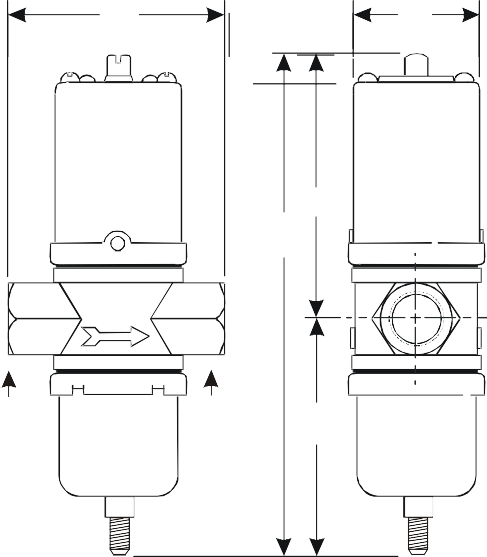
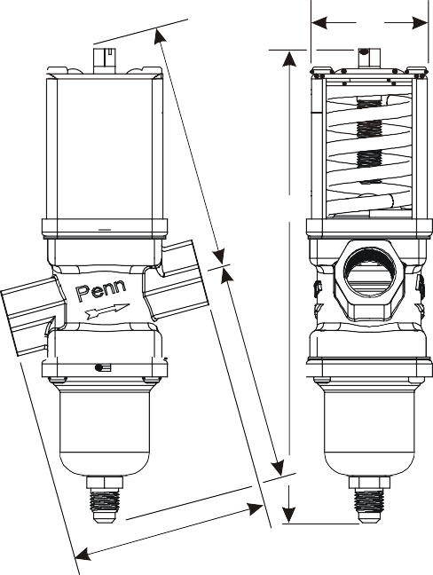 B
B
A B
D
D C
C
E
Port 1 Port 2
E
A
FIG:V246_thrdd
FIG:V246_anglbdy
V246 Screw Connection Valves Dimensions
V246 Angle-Body Screw Connection Valves Dimensions
| V246 Screw Connection Valves Dimensions | |||||
| Valve Size | Dimensions in Inches (Millimeters) | ||||
| A | B | C | D | E | |
| 3/8 in. | 2-5/8 (67) | 1-5/8 (41) | 6-1/2 (166) | 3-1/2 (89) | 3 (77) |
| 1/2 in. | 3-1/16 (78) | 2 (51) | 7-3/16 (182) | 3-13/16 (96) | 3-3/8 (86) |
| 3/4 in. | 3-3/8 (86) | 2-3/16 (55) | 8 (203) | 4-3/16 (106) | 3-13/16 (98) |
| 1 in. | 4-3/4 (121) | 2-13/16 (71) | 10-1/2 (267) | 5-15/16 (151) | 4-9/16 (116) |
| 1-1/4 in. | 4-3/4 (121) | 2-13/16 (71) | 10-7/8 (276) | 6-1/8 (156) | 4-3/4 (121) |
| V246 Angle-Body Screw Connection Valves Dimensions | |||||
| Valve Size | Dimensions in Inches (Millimeters) | ||||
| A | B | C | D | E | |
| 3/8 in. | 2-3/4 (70) | 1-5/8 (41) | 6-15/16 (176) | 3-5/8 (92) | 3-1/8 (80) |
| 1/2 in. | 3-1/8 (80) | 2 (51) | 7-1/2 (191) | 3-7/8 (98) | 3-1/2 (88) |
| 3/4 in. | 3-9/16 (90) | 2-1/8 (55) | 8-9/16 (217) | 4-5/16 (110) | 4 (101) |
FIG:V246_unnbdy
Valves and Valve Accessories
![]() V246 Series Two-Way Pressure-Actuated Water-Regulating Valves for High-Pressure Refrigerants (Continued)
V246 Series Two-Way Pressure-Actuated Water-Regulating Valves for High-Pressure Refrigerants (Continued)
![]()
![]()
![]()
![]()
![]()
![]()
![]()
![]()
![]()
![]()
![]()
![]()
![]()
![]()
![]()
![]()
A
B
D
C
Port 1
Port 2
E
V246 Union Sweat Connection Valves Dimensions
V246 Union Sweat Connection Valves Dimensions
![]()
![]()


![]()
![]()
![]()
![]()
![]()
![]()
![]()
![]()
![]()
F
G
H
FIG:flng_bdy
| Valve Size | Dimensions in Inches (Millimeters) | ||||
| A | B | C | D | E | |
| 1-1/4 in. | 4-3/4 (121) | 2-13/16 (71) | 10-7/8 (276) | 6-1/8 (156) | 4-3/4 (121) |
![]()
![]()
![]()
![]()
![]()
![]()
![]()
![]()
![]()
![]()
![]()
A
B
C
E
D
V246 Flange Valve Dimensions
Valves and Valve Accessories
![]() V246 Series Two-Way Pressure-Actuated Water-Regulating Valves for High-Pressure Refrigerants (Continued)
V246 Series Two-Way Pressure-Actuated Water-Regulating Valves for High-Pressure Refrigerants (Continued)
![]()
![]()
![]()
V246 Flange Valve, Commercial Service – Dimensions
| Valve
Size |
Dimensions in Inches (Millimeters) | |||||||
| A | B | C | D | E | F | G | H | |
| 1-1/2 in. | 5-5/16 (135) | 9/16 (14) | 6-1/8 (156) | 4-3/4 (121) | 10-7/8 (276) | 5-1/4 (133)1 | 2-5/8 (67) | 1-7/8 (48) |
| 2 in. | 6-5/8 (168) | 5/8 (16) | 7-1/8 (181) | 6-1/8 (156) | 13-1/4 (336) | 6-3/16 (157)2 | 3-1/2 (89) | 2-1/4 (57) |
- The dimensions on the European versions are 5-29/32 in. (150 mm).
- The dimensions on the European versions are 6-1/2 in. (165 mm).
V246 Flange Valve, Commercial Service – Flange Specifications
| Valve Size | Regional Version | Number of Holes | Hole Size | Bolt Circle |
| 1-1/2 in. | North American | 4 | 5/8 in. (16 mm) | 3-7/8 in. (98 mm) |
| 2 in. | 3/4 in. (19 mm) | 4-3/4 in. (121 mm) | ||
| 1-1/2 in. | European, DIN2533 Flanges | 4 | 18 mm | 110 mm |
| 2 in. | 125 mm |
V246 Flange Valve, Maritime Service – Dimensions
| Valve
Size |
Dimensions in Inches (Millimeters) | |||||||
| A | B | C | D | E | F | G | H | |
| 1-1/2 in. | 5-5/16 (135) | 9/16 (14) | 6-1/8 (156) | 4-3/4 (121) | 10-7/8 (276) | 5-1/4 (133)1 | 2-5/8 (67) | 1-7/8 (48) |
| 2 in. | 6-3/8 (162) | 5/8 (16) | 7-1/8 (181) | 6-1/8 (156) | 13-1/4 (337) | 6
(152)2 |
3-1/2 (89) | 2-3/4 (70) |
- The dimensions on the European versions are 5-29/32 in. (150 mm).
- The dimensions on the European versions are 6-1/2 in. (165 mm).
V246 Flange Valve, Maritime Service – Flange Specifications
| Valve Size | Regional Version | Number of Holes | Hole Size | Bolt Circle |
| 1-1/2 in. | North American | 4 | 5/8 in. (16 mm) | 3-7/8 in. (98 mm) |
| 2 in. | 3/4 in. (19 mm) | 4-3/4 in. (121 mm) | ||
| 1-1/2 in. | European, DIN86021 Flanges | 4 | 18 mm | 110 mm |
| 2 in. | 125 mm |
Materials
North American V246 Materials
| Nominal Valve Size: | 3/8 in. to 3/4 in.
(Commercial) |
1 in. to 2 in.
(Commercial) |
Maritime (All Sizes) | |
| Material | ||||
| Body | Cast brass | Cast iron/rust resisting finish | Cast bronze | |
| Seat | Aluminum Bronze | Aluminum bronze | Monel | |
| Disc | BUNA-N | BUNA-N | BUNA-N | |
| Disc Cup | Brass | Brass | Monel | |
| Disc Stud | Brass | Brass | Monel | |
| Stem/Extension Sleeve | Brass | Brass | Monel | |
| Diaphragms | Nylon reinforced BUNA-N | Nylon reinforced BUNA-N | Nylon reinforced BUNA-N | |
| Refrigerant Contact | ||||
| Pressure Element | Cup | 300 Series stainless steel | 300 Series stainless steel | 300 Series stainless steel |
| Bellows | 300 Series stainless steel | 300 Series stainless steel | 300 Series stainless steel | |
| Bellows Ring | Steel/nickel plated | Steel/nickel plated | Steel/nickel plated | |
Valves and Valve Accessories
![]() V246 Series Two-Way Pressure-Actuated Water-Regulating Valves for High-Pressure Refrigerants (Continued)
V246 Series Two-Way Pressure-Actuated Water-Regulating Valves for High-Pressure Refrigerants (Continued)
![]()
![]()
![]()
European V246 Materials
| Nominal Valve Size: | 3/8 in. to 3/4 in.
(Commercial) |
1 in. to 2 in.
(Commercial) |
Maritime (All sizes) | |
| Material | ||||
| Body | Hot forged brass | Cast iron/rust resisting finish | Cast bronze | |
| Seat | Aluminum bronze | Aluminum bronze | Monel | |
| Disc | BUNA-N | BUNA-N | BUNA-N | |
| Disc Cup | Brass | Brass | Monel | |
| Disc Stud | Brass | Brass | Monel | |
| Stem/Extension Sleeve | Brass | Brass | Monel | |
| Diaphragms | Nylon reinforced BUNA-N | Nylon reinforced BUNA-N | Nylon reinforced BUNA-N | |
| Refrigerant Contact | ||||
| Pressure Element | Cup | 300 Series stainless steel | 300 Series stainless steel | 300 Series stainless steel |
| Bellows | 300 Series stainless steel | 300 Series stainless steel | 300 Series stainless steel | |
| Bellows Ring | Steel/nickel plated | Steel/nickel plated | Steel/nickel plated | |
Technical Specifications
| V246 Series 2-Way Pressure-Actuated Water-Regulating Valves for High-Pressure Refrigerants | |
| Factory-Set Opening Point | Direct Acting 200 psig (13.8 bar), Reverse Acting 165 psig (11.4 bar) |
| Maximum Working Pressure | 630 psig (43.4 bar) |
| Opening Point Adjustment Range | Direct Acting 200 to 400 psi (13.8 to 27.6 bar), Reverse Acting 135 to 300 psi (9.3 to 20.7 bar) |
| Media | 150 psig (10.3 bar) Maximum,
-4F to 170F (-20C to 77C) glycol/water or liquids with low freezing points that are compatible with valve materials |
Valves and Valve Accessories Code No. LIT-1900576
![]()
Description
V248 Series Three-Way Pressure-Actuated Water-Regulating Valves for High-Pressure Refrigerants
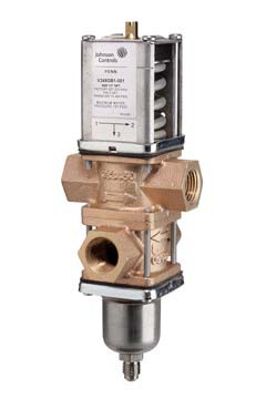 Features
![]()
![]()
![]()
The V248 Series Three-Way
Pressure-Actuated Water-Regulating Valves for High-Pressure Refrigerants regulate water flow and control refrigerant head pressure in systems with single or multiple water-cooled condensers.
V248 valves have an adjustable opening point in a refrigerant pressure range of 200 to
400 psi (13.8 to 27.6 bar). V248 valves are available in 1/2 in. through 1-1/2 in. size for use with standard, non-corrosive,
high-pressure refrigerants.
Maritime models, which have nickel copper (Monel®) internal parts, are available for applications where the media may be corrosive to the internal parts.
Refer to the V248 Series 3-Way
Pressure-Actuated Water-Regulating Valves for High-Pressure Refrigerants Product Bulletin (LIT-12011515) for important product application information.
• no close fitting or sliding parts in water passages
• accessible range spring
• take-apart construction
• pressure-balanced design
• corrosion-resistant material for internal parts
Repair Information
If the V248 Series Three-Way
Pressure-Actuated Water-Regulating Valves for High-Pressure Refrigerants fails to operate within its specifications, refer to the V248 Series 3-Way Pressure-Actuated
Water-Regulating Valves for High-Pressure Refrigerants Product Bulletin (LIT-12011515) for a list of repair parts available.
Selection Charts
North American Standard Production Models – Range 200 to 400 psi
V248 Screw Connection Valve
European Standard Production Models – Range 13.8 to 27.8 bar
Valves and Valve Accessories
![]() V248 Series Three-Way Pressure-Actuated Water-Regulating Valves for High-Pressure Refrigerants (Continued)
V248 Series Three-Way Pressure-Actuated Water-Regulating Valves for High-Pressure Refrigerants (Continued)
![]()
![]()
![]()
Applications
Each application is unique and requires specific engineering data to properly size and design a system to fulfill the appropriate requirements. Typically, a valve is replaced with another valve of the same size in a properly sized and engineered system. In North America, contact Johnson Controls/PENN® Refrigeration Application Engineering at 1-800-275-5676 to obtain specific engineering data. In other areas, contact the local Johnson Controls® sales office to obtain specific engineering data.
To make a rough field estimate of the size of valve for an application, find the valve size needed by locating a point on a flow chart that satisfies these requirements:
• water flow required by the condenser (Flow)
• refrigerant head pressure rise (PRISE)
• available water pressure (PAVAIL)
Follow these steps, and use the information obtained to locate a point on one of the flowcharts that satisfies all three steps.
1. Take the water flow required by the condenser (Flow) from information provided by the manufacturer of the condensing unit. If the manufacturer’s information is unavailable, use the following information to make a rough approximation of water flow in gallons per minute (gpm) [cubic meters per hour (m3/hr)]:
• System Capacity (Tons of Refrigeration)
• Outlet Water Temperature (Temp. Outlet)
• Inlet Water Temperature (Temp. Inlet)
PRISE = PCOND – POPEN
Refrigerant Head Pressure Rise
FIG:eqn_hd_prssr_rs
- Determine the available water pressure to the valve (PAVAIL) using the following steps. This the actual water pressure available to force water through the valve.
- Determine the minimum inlet pressure (PIN). This is the water pressure from city water mains, pumps, or other sources.
- Pressure drop through condenser (PCOND) is the difference in water pressure between the condenser inlet and the condenser outlet. Obtain this information from the condenser manufacturer.
- Estimate or calculate the pressure drop through all associated piping (PLOSS).
- Subtract the PCOND and PLOSS from PIN. The result is PAVAIL.
![]()
![]()
FIG:3wy_prss_drp
Cooling Tower
Pump
P
Calculate the flow using the following formula:
Tons of Refrigeration x 30
P2 P1
Condenser
IN
- Way
Valve
Flow = P P
FIG:flw_eqn
(Temp.Outlet – Temp.Inlet)
Flow Required
Note: If the outlet temperature is unknown, assume it to be 10F (6C) above the inlet temperature.
- Determine refrigerant head pressure rise above the valve opening point (PRISE) using the following steps:
- The Valve Closing Pressure (PCLOSE) is equal to the
Loss 2
![]()
Loss 1
Balancing Valve Bypass Line
PCOND= P1 – P2
P
=
LOSS
P
Loss 1 Loss 2
+ P
+ …
Available Water Pressure
![]()
PAVAIL= PIN – ( PCOND + PLOSS)
refrigerant pressure at the highest ambient temperature the refrigeration equipment experiences in the Off cycle. Use a Pressure-Temperature Chart for the refrigerant selected to find this pressure.
-
- To approximate the Valve Opening Pressure (POPEN), add about 10 psig (0.7 bar) to the Valve Closing Pressure.
POPEN = PCLOSE +10 psi (0.7 bar)
FIG:eqn_opn_prssr
4. Select the proper valve size from the flowcharts by locating a point on a chart that satisfies the flow, the head pressure rise above opening point, and the pressure drop across the valve.
Metric Conversions
Use these equations to convert between U.S. and S.I. units.
-
- 1 dm3/s = 3.6 m3/h = 15.9 U.S. gal. /min. = 13.2 U.K. gal. /min.
- 1 bar = 100 kPa = 0.1 MPa 1.02 kg/cm2 = 0.987 atm 14.5 psig
Valve Opening Pressure
-
- From the Pressure-Temperature Chart for the refrigerant selected, read the Refrigerant Condensing Pressure (PCOND) (operating head pressure) corresponding to the selected
condensing temperature.
-
- Subtract the Valve Opening Pressure from the Refrigerant Condensing Pressure. This gives the head pressure rise.
Valves and Valve Accessories
![]() V248 Series Three-Way Pressure-Actuated Water-Regulating Valves for High-Pressure Refrigerants (Continued)
V248 Series Three-Way Pressure-Actuated Water-Regulating Valves for High-Pressure Refrigerants (Continued)
![]()
![]()
![]()
V248 Flowcharts
The maximum recommended differential water pressure across a valve is 20 psig (1.4 bar).
Refrigerant Head Pressure Above Opening PRise (bar)
Flow (gpm) 18
15
0.7 1.4 2.1 2.8 3.5 4.1 4.8 5.5 6.2 6.9
4.1
Pressure Drop Through Valve, psig (bar)
20 (1.4)
14.5 (1.0)
10 (0.7)
5 (0.3)
2 (0.1)
3.4
Flow (m³/hr)
12 2.7
9 2.0
6 1.4
3 0.7
FIG:V248_0.5 in. graph
0
10 20 30 40 50 60 70 80 90 100 110
Refrigerant Head Pressure Above Opening PRise ( psig )
1/2 in. Direct Acting Valve Flowchart
0.0
Flow (gpm)
Refrigerant Head Pressure Above Opening PRise (bar)
0.7 1.4 2.1 2.8 3.5 4.1 4.8 5.5 6.2 6.9
25
20 (1.4)
Pressure Drop Through Valve, psig (bar)
14.5 (1.0)
10 (0.7)
5 (0.3)
2 (0.1)
5.7
Flow (M³/hr)
20 4.5
15 3.4
10 2.3
5 1.1
FIG:V248_0.75 in. graph
0
10 20 30 40 50 60 70 80 90 100 110
Refrigerant Head Pressure Above Opening PRise ( psig )
3/4 in. Direct Acting Valve Flowchart
0.0
Valves and Valve Accessories
![]() V248 Series Three-Way Pressure-Actuated Water-Regulating Valves for High-Pressure Refrigerants (Continued)
V248 Series Three-Way Pressure-Actuated Water-Regulating Valves for High-Pressure Refrigerants (Continued)
![]()
![]()
![]()
Flow 50 (gpm)
40
30
20
Refrigerant Head Pressure Above Opening PRise (bar)
0.7 1.4 2.1 2.8 3.5 4.1 4.8 5.5 6.2 6.9
11.4
Pressu
re Drop
20 (1.4)
Throug
psig
h Valve,
(bar)
14.5 (1.0)
10 (0.7)
5 (0.3)
2 (0.1)
9.1
6.8
4.5
Flow (m³/hr)
10 2.3
FIG:V248_1.0 in. graph
0
10 20 30 40 50 60 70 80 90 100 110
Refrigerant Head Pressure Above Opening PRise ( psig )
1 in. Direct Acting Valve Flowchart
0.0
Flow (gpm)
70
60
50
Refrigerant Head Pressure Above Opening PRise (bar)
0.7 1.4 2.1 2.8 3.5 4.1 4.8 5.5 6.2 6.9
15.9
Pressu
re Drop
20 (1.4)
Throug
psig
h Valve,
(bar)
14.5 (1.0)
10 (0.7)
5 (0.3)
2 (0.1)
13.6
11.4
Flow (m³/hr)
40 9.1
30 6.8
20 4.5
10 2.3
FIG:V248_1.25 in. graph
0
10 20 30 40 50 60 70 80 90 100 110
Refrigerant Head Pressure Above Opening PRise ( psig )
1-1/4 in. Direct Acting Valve Flowchart
0.0
Flow (gpm)
Refrigerant Head Pressure Above Opening PRise (bar)
0.7 1.4 2.1 2.8 3.5 4.1 4.8 5.5 6.2 6.9
80
Pressu Throug
re Drop h Valve,
20 (1.4)
psig
(bar)
14.5 (1.0)
10 (0.7)
5 (0.3)
2 (0.1)
70
60
50
40
30
20
10
0
18.2
15.9
13.6
11.4
9.1
6.8
4.5
2.3
0.0
Flow (m³/hr)
10 20 30 40 50 60 70 80 90 100 110
FIG:V248_1.5 in. graph
Refrigerant Head Pressure Above Opening PRise ( psig )
1-1/2 in. Direct Acting Valve Flowchart
Valves and Valve Accessories
![]() V248 Series Three-Way Pressure-Actuated Water-Regulating Valves for High-Pressure Refrigerants (Continued)
V248 Series Three-Way Pressure-Actuated Water-Regulating Valves for High-Pressure Refrigerants (Continued)
![]()
![]()
![]()
![]()
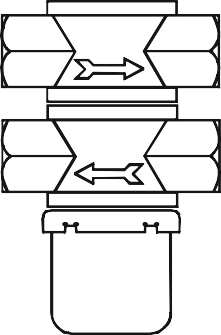
![]()
![]()
![]()
![]()


![]()
![]()
![]()
![]()
![]()
![]()
![]()
![]()
![]()
A
B
D
Port 1
Port 2 C
E
Port 3
Plugged
F
![]()
![]()
![]()
![]()
![]()
![]()
![]()
![]()
![]()
![]()
![]()
![]()
![]()
![]()
![]()
![]()
A
B
C
Port 1
Port 2
D
E
Port 3
Plugged
F
V248 1/2 in. Through 1-1/4 in. Screw Connection Valves Dimensions
FIG:V248_thdd
FIG:V248_unbdy
V248 Union Sweat Connection Valves Dimensions
V248 1-1/2 in. Screw Connection Valves Dimensions
![]()
![]()
![]()
![]()
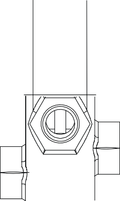
![]()
![]()
![]()
![]()
![]()
![]()
![]()
E
PORT 3
PORT 1
PORT 2
FIG:V248_3 way valve
Valves and Valve Accessories
![]() V248 Series Three-Way Pressure-Actuated Water-Regulating Valves for High-Pressure Refrigerants (Continued)
V248 Series Three-Way Pressure-Actuated Water-Regulating Valves for High-Pressure Refrigerants (Continued)
![]()
![]()
![]()
V248 1/2 in. Through 1-1/4 in. Screw Connection Valves Dimensions
| Valve Size | Dimensions in Inches (Millimeters) | |||||
| A | B | C | D | E | F | |
| 1/2 in. | 3-1/16 (78) | 2 (51) | 8-11/16 (220) | 3-13/16 (96) | 1-1/2 (38) | 3-3/8 (86) |
| 3/4 in. | 3-3/8 (86) | 2-3/16 (55) | 9-3/4 (248) | 4-3/16 (106) | 1-3/4 (44) | 3-13/16 (98) |
| 1 in. | 4-3/4 (121) | 2-13/16 (71) | 12-1/2 (318) | 5-15/16 (151) | 2-1/16 (52) | 4-1/2 (114) |
| 1-1/4 in. | 4-3/4 (121) | 2-13/16 (71) | 13-1/4 (336) | 6-1/8 (156) | 2-3/8 (60) | 4-3/4 (121) |
V248 Union Sweat Connection Valves Dimensions
| Valve Size | Dimensions in Inches (Millimeters) | |||||
| A | B | C | D | E | F | |
| 3/4 in. | 3-3/8 (86) | 2-3/16 (55) | 9-3/4 (248) | 4-3/16 (106) | 1-3/4 (44) | 3-13/16 (98) |
| 1 in. | 4-3/4 (121) | 2-13/16 (71) | 12-1/2 (318) | 5-15/16 (151) | 2-1/16 (52) | 4-1/2 (114) |
| 1-1/4 in. | 4-3/4 (121) | 2-13/16 (71) | 13-1/4 (336) | 6-1/8 (156) | 2-3/8 (60) | 4-3/4 (121) |
V248 1-1/2 in. Screw Connection Valves Dimensions
| Valve Size | Dimensions in Inches (Millimeters) | |||||
| A | B | C | D | E | F | |
| 1-1/2 in. | 6 (152) | 3-1/2 (89) | 15-1/4 (382) | 8 (203) | 9-5/16 (237) | 6-7/8 (175) |
Valves and Valve Accessories
![]()
Materials
![]()
![]()
![]()
V248 Series Three-Way Pressure-Actuated Water-Regulating Valves for High-Pressure Refrigerants (Continued)
North American V248 Materials
| Nominal Valve Size: | 3/8 in. to 3/4 in.
(Commercial) |
1 in. to 1-1/2 in.
(Commercial) |
Maritime (All Sizes) | |
| Material | ||||
| Body | Cast brass | Cast iron/rust resisting finish | Cast bronze | |
| Seat | Aluminum bronze | Aluminum bronze | Monel | |
| Disc | BUNA-N | BUNA-N | BUNA-N | |
| Disc Cup | Brass | Brass | Monel | |
| Disc Stud | Brass | Brass | Monel | |
| Stem/Extension Sleeve | Brass | Brass | Monel | |
| Diaphragms | Nylon reinforced BUNA-N | Nylon reinforced BUNA-N | Nylon reinforced BUNA-N | |
| Refrigerant Contact | ||||
| Pressure
Element |
Cup | 300 Series stainless steel | 300 Series stainless steel | 300 Series stainless steel |
| Bellows | 300 Series stainless steel | 300 Series stainless steel | 300 Series stainless steel | |
| Bellows Ring | Steel/nickel plated | Steel/nickel plated | Steel/nickel plated | |
European V248 Materials
| Nominal Valve Size: | 3/8 in. to 3/4 in.
(Commercial) |
1 in. to 1-1/2 in.
(Commercial) |
Maritime (All Sizes) | |
| Material | ||||
| Body | Hot forged brass | Cast iron/rust resisting finish | Cast bronze | |
| Seat | Aluminum bronze | Aluminum bronze | Monel | |
| Disc | BUNA-N | BUNA-N | BUNA-N | |
| Disc Cup | Brass | Brass | Monel | |
| Disc Stud | Brass | Brass | Monel | |
| Stem/Extension Sleeve | Brass | Brass | Monel | |
| Diaphragms | Nylon reinforced BUNA-N | Nylon reinforced BUNA-N | Nylon reinforced BUNA-N | |
| Refrigerant Contact | ||||
| Pressure Element | Cup | 300 Series stainless steel | 300 Series stainless steel | 300 Series stainless steel |
| Bellows | 300 Series stainless steel | 300 Series stainless steel | 300 Series stainless steel | |
| Bellows Ring | Steel/nickel plated | Steel/nickel plated | Steel/nickel plated | |
Technical Specifications
| V248 Series Pressure-Actuated Water-Regulating Valves for High-Pressure Refrigerants | |
| Maximum Working Pressure | 630 psig (43.4 bar) |
| Factory-Set Opening Point (Port 1 to Port 2) | 275 psig (19.0 bar) |
| Opening Point Adjustment Range (Port 1 to Port 2) | 200 to 400 psi (13.8 to 27.6 bar) |
| Throttling Range | 120 psi (8.3 bar) for 1/2 in. size
100 psi (6.9 bar) for 3/4 in., 1 in., and 1-1/4 in. sizes 140 psi (9.6 bar) for 1-1/2 in. size |
| Media | 150 psig (10.3 bar) maximum,
-4F to 170F (-20C to 77C) glycol/water or liquids with low freezing points that are compatible with valve materials |
Valves and Valve Accessories Code No. LIT-1927340
 STT Water Valve Renewal Kit for V46, V47, and V48 Series Valves
![]()
![]()
![]()
Description
These renewal kits include a seat, disc, diaphragms, and all additional internal parts required to recondition the valves.
Selection Chart
Valves and Valve Accessories Code No. LIT-1900112
 Companion Flanges and Gaskets for V43, V46, and V47 Series Valves
![]()
![]()
![]()
Description
Companion flanges and gaskets are sold individually or in kits. The kits contain two flange gaskets, two cast iron flanges with NPT (National Pipe Thread), eight hex nuts, and eight machine bolts.
Cast Iron Flange (Two)
| Valve Size | Valve Series | ||
| V43 Series | V46 Series | V47 Series | |
| Flange Gaskets (One gasket per package) | |||
| 1-1/2 in. | — | 246-423 | |
| 2 in. | 246-424 | ||
| 2-1/2 in. | 246-425 | ||
| Companion Flange Kits (See diagram) | |||
| 1-1/2 in. | — | KIT14A-6121 | KIT14A-612 |
| 2 in. | KIT14A-6131 | KIT14A-6131 | KIT14A-613 |
| 2-1/2 in. | KIT14A-6141 | KIT14A-6141 | KIT14A-614 |
| 3 in. | FLG15A-6001 | — | — |
| 4 in. | FLG15A-6011 | — | — |
Selection Chart
Flange
Gasket (Two)
Hex Nut (Eight)
![]()
Companion Flange Kit
Machine Bolt (Eight)
![]()
![]()
Repair Information
If the Companion Flanges and Gaskets for V43, V46, and V47 Series Valves fail to operate within its specifications, replace the unit. For a replacement flange or gasket, contact the nearest Johnson Controls® representative.
![]()
![]()
![]()
Code No. LIT-1922175
Y63, Y64, Y65, Y66, and Y69 Series Transformers
![]()
Description
The Y63, Y64, Y65, Y66, and Y69 Series Transformers provide 24 VAC power for loads of 40 VA through 300 VA. These transformers are designed for use on digital controllers, gas controls, ignition systems, motor actuators, staging controls, and most other 24 VAC HVAC/R control systems.
The Y6x Series meets the requirements of UL 1585, UL 506, and CSA C22.2 No. 66,
providing compliance in both the United States and Canada. The Y63, Y64, Y65, and Y66 transformers are listed as Class 2 transformers (UL 1585, CSA C22.2 No. 66). The Y69 is listed as a general purpose transformer (UL 506, CSA C22.2 No. 66).
Refer to the Series Y63, Y64, Y65, Y66, and Y69 Transformers Product Bulletin
(LIT-125755) for important product application information.
Features
-
- split-bobbin design provides best primary/secondary isolation
- multi-tap primaries reduce stocking requirements and offer application flexibility
- choice of foot, plate, or conduit hub mounting provides mounting flexibility
- choice of primary voltages meets a wide range of power requirements from 24 VAC through 480 VAC
- color-coded lead wires provide simplicity and standardization
- cULus listed or cURus recognized meets US and Canadian requirements for Class 2 transformers (Y63, Y64, Y65, and Y66) and general purpose transformers (Y69)
- built-in, easy-reset circuit breakers eliminate replacement time and cost caused by burn-out (Y63, Y64, Y66, and Y69)
- open frame Y65 models serve as ideal models when end bells are not required
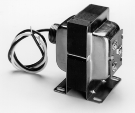
Y65 Series Transformer
Repair Information
Do not make any field repairs to transformers. For a replacement transformer, contact the nearest Johnson Controls® distributor or sales representative.
Selection Chart
Y63, Y64, Y65, Y66, and Y69 Series Transformers (Part 1 of 2)
| Product Code
Number |
Primary
Voltage VAC |
Secondary
Voltage VAC |
Primary
Connection |
Secondary
Connection |
Mounting | Agency
Requirement |
| 40 VA Capacity Transformers with Energy Limiting Type Overload Protection | ||||||
| Y65G13-0 | 24 | 24 | External Fitting | External Fitting
30 in. secondary leads |
Foot | cULus Class 2 |
| Y65A13-0 | 120 | 24 | External Fitting | External Fitting
30 in. secondary leads |
Foot | cULus Class 2 |
| Y65A21-0 | 120 | 24 | End bell holes | Three screw terminals (one is blind) | 4 in. x 4 in. plate | cULus Class 2 |
| Y65T31-0 | 120/208/240 | 24 | External Fitting | Three screw terminals (one is blind) | Foot
4 in. x 4 in. plate1 |
cULus Class 2 |
| Y65T42-0 | 120/208/240 | 24 | Common External Fitting 8 in. primary leads | Common External Fitting 8 in. secondary leads | Hub
4 in. x 4 in. plate1 |
cURus Class 2 |
| Y65T54-0 | 120/208/240 | 24 | 8 in. primary leads | 8 in. secondary leads | Foot-skeleton | cURus Class 2 |
| Y65S13-0 | 208/240 | 24 | External Fitting | External Fittings
30 in. secondary leads |
Foot | cULus Class 2 |
| Y65F13-0 | 277/480 | 24 | External Fitting | External Fitting
30 in. secondary leads |
Foot | cULus Class 2 |
| Y65F42-0 | 277/480 | 24 | Common External Fitting 8 in. primary leads | Common External Fitting 8 in. secondary leads | Hub
4 in. x 4 in. plate1 |
cURus Class 2 |
| 50 VA Capacity Transformers with Circuit Breakers | ||||||
| Y63T22-0 | 120/208/240 | 24 | End bell Hole | End bell Hole
8 in. secondary leads |
4 in. x 4 in. plate | cURus Class 2 |
| Y63T31-0 | 120/208/240 | 24 | External Fitting | Three screw terminals (one is blind) | Foot
4 in. x 4 in. plate1 |
cULus Class 2 |
| Y63F22-0 | 277/480 | 24 | End bell Hole
8 in. primary leads |
End bell Hole
8 in. secondary leads |
4 in. x 4 in. plate | cURus Class 2 |
Relays and Transformers
Y63, Y64, Y65, Y66, and Y69 Series Transformers (Continued)
![]()
![]()
![]()
![]()
Y63, Y64, Y65, Y66, and Y69 Series Transformers (Part 2 of 2)
1. 4 in. x 4 in. plate and nut packed with transformer.
Technical Specifications
| Series Y63, Y64, Y65, Y66, Y69 Transformers | ||
| Input Power Requirements | 24 to 480 VAC at 60 Hz | |
| Full Load Secondary Voltage | 23.5 VAC (Nominal) | |
| Open Circuit Secondary Voltage (No Load) | 27.0 VAC (Nominal) | |
| Full Load Secondary VA Rating | Series Y63 Y64 Y65 Y66 Y69 | Volt-Amperes
50 VA 92 VA 40 VA 75 VA 300 VA |
| Finish | End bells, frame, feet, and mounting plates are corrosion resistant | |
| Ambient Operating Temperature | -40 to 104°F (-40 to 40°C) | |
| Ambient Storage Temperature | -40 to 140°F (-40 to 60°C) | |
| Shipping Weight | Y63 Y64 Y65 Y66 Y69 | 3.0 lb/1.4 kg
4.0 lb/1.8 kg 2.0 lb/0.9 kg 3.0 lb/1.4 kg 11.0 lb/5.0 kg |
| Agency Compliance | UL Listed Y63, Y64, Y65, Y66; File E95575, CCN’s XOKV (US) and XOKV7 (Canada)
UL Recognized Y63, Y64, Y65, Y66; File E95575, CCN’s XOKV2 (US) and XOKV8 (Canada) UL Listed Y69; File E95138, CCN’s XPTQ (US) and XPTQ7 (Canada) All transformers are Class 2 except the Y69 (300 VA), which is listed as a power transformer. |
|
![]()
![]()
![]()
Code No. LIT-1900549
System 450™ Series Modular Controls
![]()
Description
System 450™ is a family of modular, digital electronic controls that is easily assembled and set up to provide reliable temperature, pressure, and humidity control for a wide variety of HVAC/R applications, commercial process applications, and industrial process applications.
The System 450 control system is designed to replace System 350™ and System 27 control systems, and to provide many additional features and benefits with fewer than twenty model variations.
System 450 control modules provide a field-configurable
out-of-the-box solution. Most System 450 control modules can control temperature, pressure, and humidity systems simultaneously.
System 450 Control Modules with Communications enable you to connect System 450 control systems to Modbus® or Ethernet networks for remote monitoring and setup. The Modbus communications control module is an RS485, RTU-compliant slave device. The Ethernet communications control module has an integral web server that can deliver web pages by means of a direct connection, on your LAN, or across the Internet.
System 450 Reset Control Modules provide many of the features of the standard models for temperature and humidity control. In addition, these modules provide setpoint reset, real-time setback scheduling, and run-time balancing (equal run time) capability.
The System 450 Control Module with Hybrid Analog Output has a single self-selecting analog output to optimize and extend the controlled speed range of variable speed electronically commutated (EC) motors.
Refer to the following documents for important product application information.
-
- System 450™ Series Modular Controls Product Bulletin (LIT-12011458)
- System 450™ Series Modular Control Systems with Standard Control Modules Technical Bulletin (LIT-12011459)
- System 450™ Series Modular Control Systems with Reset Control Modules Technical Bulletin (LIT-12011842)
- System 450™ Series Modular Control Systems with Communications Control Modules Technical Bulletin (LIT-12011826)
Features
- durable, compact, interchangeable modular components with
plug-together connectors and DIN rail or direct wall mount capability eliminate field wiring between modules and allow you to quickly and easily design, assemble, install, and upgrade your control systems.
- versatile, multipurpose, field-configurable control modules and expansion modules designed for global use allow you to create a wide variety of application-specific control systems capable of controlling temperature, pressure, or humidity, or all three conditions simultaneously, with only a small suite of module models.
- up to three hard-wired input sensors and up to ten relay or analog outputs (in any combination) per control system allow you to build complex custom control systems while reducing your control system cost to only the cost of the required components.
- control Modules with bright backlit LCDs and four-button touch pad user interfaces provide quick, clear, visual status of your
System 450 control system inputs and outputs with the touch of a button and enable you to quickly and easily set up and adjust your control system.
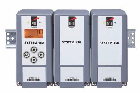
System 450 Control System with a Control, Power, and Expansion Module
- multipurpose, all-in-one control modules enable simple
stand-alone, single-module control systems that are temperature, pressure, and humidity capable out of the box and easy to set up in the field to replace a wide variety of OEM HVAC/R and process controls.
- an extensive suite of compatible temperature and humidity sensors, and pressure transducers allows you to monitor and control a wide range of HVAC/R and process conditions in a variety of standard and global units of measurement.
- high input signal selection enables your control system to monitor a temperature, pressure, or humidity condition with two or three sensors (of the same type) and control your system outputs based on the highest condition value sensed by the referenced sensors.
- differential control enables your control system to monitor and maintain a temperature, pressure, or humidity differential between two sensor points within a system, process, or space.
The Reset Control modules have additional features:
- adjustable minimum and maximum setpoint temperatures (reset control modules only) enable compliance with the manufacturer’s specifications for your controlled HVAC/R and process equipment.
- selectable shutdown-high and shutdown-low temperature settings (reset control modules only) saves you energy by shutting down controlled equipment when the ambient temperature either rises or drops to a point where heating or cooling is no longer required.
- real time clock and adjustable setback temperature (reset control modules only) save you energy by setting back heating, cooling, or humidity setpoints during scheduled unoccupied periods (24-hour day, 7-day week schedule).
- user-defined reset control capability (reset control modules only) saves you energy in a wide variety of temperature and humidity reset control applications by adjusting the temperature or humidity control loop, based on changes in ambient outdoor temperature or other uncontrolled condition.
System 450 Control Series
System 450™ Series Modular Controls (Continued)
![]()
![]()
![]()
![]()
The Control Modules with Communications have additional features:
- Ethernet communication capability through a built-in web server (Ethernet Control Modules only) allows you to monitor your control system status and set up or change the parameters by means of a direct Ethernet cable connection, through a LAN connection, or over the Internet. The built in web server delivers user-friendly web pages to client browsers on a desktop, laptop, tablet, or smart device.
- The Web page server on Ethernet communication modules provides a simple, intuitive web interface for easy remote monitoring, setup, adjustment and remote monitoring of your control systems across Ethernet networks.
- RS485, RTU-compliant Modbus® network communication capability (Modbus control modules only) enables a head-end RS485 Modbus master controller to read and write control system status and setup parameters to the System 450 Modbus communication control module.
- Password protection for local access (Ethernet and Modbus control modules only) and password protection for remote access (Ethernet control module only) deters unauthorized changes to the control system settings, but allows local and remote monitoring of your control system status.
- Analog output signal limiting features (communication control modules only) allow you to select the rate and condition range at which the control updates the analog output signal, potentially reducing wear on the controlled equipment.
- Binary input with time delay (communication control modules only) allows you to use an external set of dry contacts and selectable time delays to control relay outputs.
Applications
You can create a wide variety of custom, application-specific control systems with System 450 modules. The following are some common control application examples:
- Temperature control
- Pressure control
- Humidity control
- Multipurpose control
- Reset and setback control
- High input-signal selection
- Differential control
Temperature Control
- Temperature monitoring and alarming
- On/Off staged control of boilers and chillers
- Proportional stage control of boilers and chillers
- Boiler and chiller pump control
- Heating and cooling control with deadband
- Floating temperature control of damper and valve actuators
- Cooling tower fan speed/stage control based on water temperature
- Supply, make-up, and mixed air temperature control
- Temperature actuated valve control
- Supply and make-up air damper and fan control
- Condenser fan staging or speed control based on condenser temperature
Refrigerant Pressure Control
- Condenser fan cycling and stage control
- Multispeed condenser fan control
- Floating pressure control of damper and valve actuators
- Condenser fan speed and damper control
- High and low pressure cutout control
- Staged compressor control
- Cooling tower fan speed control based on high-side pressure
- Direct speed control of electronically commutated (EC) condenser fan motors (C450CPW-100 model)
Other Pressure Control
- Relief damper and fan control for building pressurization
- Constant static pressure control
Humidity Control
- On/Off humidification and dehumidification control
- Proportional humidification and dehumidification control
- Multistage humidification and dehumidification control
- Humidity monitoring and alarming
Multipurpose Control
- Temperature and pressure based refrigeration rack control
- Temperature and humidity control of wine cellars and greenhouses
- Temperature, humidity, and static pressure control of clean rooms and greenhouses
- Dehumidification with reheat control
Reset Control
- Boiler supply water temperature reset control based on outside air temperature
- Chiller supply water temperature reset control based on outside air temperature
- VAV zone temperature control based on outside air temperature
- Humidity reset based on outside air temperature
- Staged applications with runtime balancing
- Real-time Occupied/Unoccupied Setback
High Input Signal Selection
- Pressure-based fan speed or fan cycling control on multi-circuit condensers
- Temperature-based fan speed or fan cycling control on multi-circuit condensers
Differential Control
- Air and fluid pump-flow monitoring and alarming
- Air and fluid filter status monitoring and alarming
- Chiller barrel flow monitoring, control, and alarming
- Solar air and water heating applications
Note: Communications modules add network communication to any application of your choosing, except those requiring reset, setback, or EC motor control.
Repair Information
If a System 450 module fails to operate within its specifications, replace the module. For a replacement module, contact your Johnson Controls® representative.
System 450 Control Series
System 450™ Series Modular Controls (Continued)
![]()
![]()
![]()
![]()
System 450 Control Module Capabilities
| Control by | System 450 Control Modules | |||
| Standard | Communications | Reset | Hybrid | |
| C450CPN-3C
C450CQN-3C C450CBN-3C C450CCN-3C |
C450CEN-1C
C450CRN-1C |
C450RBN-3C
C450RCN-3C |
C450CPW-100C | |
| Controlled Condition | ||||
| Temperature | | | | |
| Pressure | | | – | |
| Humidity | | | | |
| Combination of Conditions | | | | |
| Control Capabilities | ||||
| On/Off Relay Control | | | | |
| Analog Proportional Control (Direct and Reverse Action) | | | | |
| Analog Proportional Plus Integral Control (Direct and Reverse Action) | | | | |
| Combination of On/Off Relay and Analog Output Control | | | | |
| Stand-Alone Control | | – | | |
| Multi-Stage Control (Relay or Analog) | | | | |
| Network Communications | – | | – | – |
| High Input Signal Selection | | | – | |
| Differential Control | | | – | |
| Output Signal Limiting Output Signal Update Rate Output Signal Deadband | – | | – | – |
| Binary Input Control for Relay Outputs | – | | – | – |
| On/Off Duration Time Control | – | | – | – |
| Temperature and Humidity Reset Control | – | – | | – |
| Scheduling and Temperature Setback Control | – | – | | – |
| Reset Setpoint Control | – | – | | – |
| Setback Scheduling | – | – | | – |
| Run-Time Balancing | – | – | | – |
| Hybrid Analog Output Control | – | – | – | 1 |
1. Only on output OUTA1.
System 450 Control Series
System 450™ Series Modular Controls (Continued)
![]()
![]()
![]()
![]()
Selection Charts
System 450 Modules and Accessories Ordering Information
System 450 Compatible A99B Temperature Sensors and Accessories Ordering Information1 (Part 1 of 2)
System 450 Control Series
System 450™ Series Modular Controls (Continued)
![]()
![]()
![]()
![]()
System 450 Compatible A99B Temperature Sensors and Accessories Ordering Information1 (Part 2 of 2)
1. Refer to the A99B Series Temperature Sensors Product/Technical Bulletin (LIT-125186) on the Johnson Controls® Product Literature website for more information.
System 450 Compatible TE-6000 Series 1,000 Ohm Nickel Temperature Sensors and Accessories Ordering Information
| Product Code | Product Description |
| TE-6000-x | TE6000 Series 1,000 ohm at 70F nickel temperature sensors (only). Only the TE-6000-6 sensor can be used for the entire HIC and HIF
temperature range. Different sensing element packages are available for various applications. For a complete list of compatible 1,000 ohm nickel sensors, including sensor descriptions, technical specifications, and mounting accessories, refer to the TE-6000 Series Temperature Sensing Elements Product Bulletin (LIT-216288). (System 450 Sensor Types HIC and HIF) |
System 450 Compatible TE-6300 Series 1,000 Ohm Nickel Temperature Sensors and Accessories Ordering Information
| Product Code | Product Description |
| TE-631xx-x | TE6300 Series 1,000 ohm at 70F nickel averaging and 1,000 ohm thin-film nickel temperature sensors (only). For a complete list of
compatible 1,000 ohm nickel averaging and thin-film nickel sensors, including sensor descriptions, technical specifications, and mounting accessories, refer to the TE-6300 Series Temperature Sensors Product Bulletin (LIT-216320). (System 450 Sensor Types HIC and HIF) |
System 450 Compatible TE-68NT-0N00S 1,000 Ohm Nickel Temperature Sensor Ordering Information
| Product Code | Product Description |
| TE-68NT-0N00S | TE6800 Series 1,000 ohm nickel temperature sensor for wall-mount applications. For more information, including sensor description,
technical specifications, and mounting accessories, refer to the TE-6800 Series Temperature Sensors Product Bulletin (LIT-12011542). (System 450 Sensor Types HIC and HIF) |
System 450 Compatible HE67S3 Type Humidity Sensors with Integral A99B Temperature Sensor Ordering Information1
1. The HE-67S3 sensors require 24 VAC input and must use the 0–5 VDC output. Refer to the TrueRH Series HE-67xx Humidity Element with Temperature Sensors Product Bulletin (LIT-216245) on the Johnson Controls Product Literature website for more information, including technical specifications and mounting accessories.
System 450 Compatible HE6800 Series Humidity Transmitters with Temperature Sensor Ordering Information1
1. The HE-6800 transmitters require 24 VAC input and must use the 0–5 VDC output. Refer to the HE-6800 Series Humidity Transmitters with Temperature Sensor Product Bulletin (LIT-12011625) on the Johnson Controls Product Literature website for more information, including technical specifications and mounting accessories.
System 450 Compatible Low Pressure Differential Transducer Ordering Information1 2
- Refer to the Setra Systems Model DPT265 Very Low Differential Pressure Transducer Catalog Page on the Johnson Controls Product Literature website for more information.
- The DPT265 sensors require 24 VAC input and must use the 0–5 VDC output. Refer to the Setra Systems Model DPT265 Very Low Differential Pressure Transducer Catalog Page on the Johnson Controls Product Literature website for more information.
- Used only with Communications Control Modules.
System 450 Control Series
System 450™ Series Modular Controls (Continued)
![]()
![]()
![]()
![]()
System 450 Compatible P499 Series Transducers with 1/4 in. SAE 45 Flare Internal Thread with Depressor (Style 47) Ordering Information1
1. The P499 sensors must be powered with the +5 VDC and C terminals and the output is 0.5 to 4.5 VDC. Refer to the P499 Series Electronic Pressure Transducers Product/Technical Bulletin (LIT-12011190) on the Johnson Controls Product Literature website for more information.
System 450 Compatible P499 Series Transducers with 1/8 in. 27 NPT External Thread (Style 49) Ordering Information1
1. The P499 sensors must be powered with the +5 VDC and C terminals and the output is 0.5 to 4.5 VDC. Refer to the P499 Series Electronic Pressure Transducers Product/Technical Bulletin (LIT-12011190) on the Johnson Controls Product Literature website for more information.
WHA-PKD3 Wire Harnesses Ordering Information1
1. Refer to the P499 Series Electronic Pressure Transducers Product/Technical Bulletin (LIT-12011190) on the Johnson Controls Product Literature website for more information.
Technical Specifications
| C450CPN-3C and C450CQN-3C Control Modules with Analog Output (Part 1 of 2) | |
| Product | C450CPN-3C and C450CQN-3C: System 450 Control Module models are sensing controls and operating controls with
LCD, four-button touchpad, and SPDT analog output C450CPN-3C: Control Module with one analog output C450CQN-3C: Control Module with two analog outputs |
| Power Consumption | C450CPN-3C: 1.3 VA maximum using 0 to 10 V out; 1.5 VA maximum using 4 to 20 mA out
C450CQN-3C: 2.0 VA maximum using 0 to 10 V out; 2.4 VA maximum using 4 to 20 mA out |
| Supply Power | Internal Supply Power: C450YNN-1C Power Supply Module
External Supply Power: 24 VAC (20 to 30 VAC) Safety Extra-Low Voltage (SELV) (Europe), Class 2 (North America), 50/60 Hz, 10 VA minimum Note: A System 450 control module or module assembly can use an internal or an external supply power source, but must not be connected to both simultaneously. |
System 450 Control Series
System 450™ Series Modular Controls (Continued)
![]()
![]()
![]()
![]()
| C450CPN-3C and C450CQN-3C Control Modules with Analog Output (Part 2 of 2) | |
| Ambient Operating Conditions | Temperature: -40 to 66C (-40 to 150F) when using 0–10 VDC outputs;
-40 to 40C (-40 to 104F) when using 4–20 mA outputs Humidity: Up to 95% RH noncondensing; maximum dew point 29C (85F) |
| Ambient Shipping and Storage Conditions | Temperature: -40 to 80C (-40 to 176F)
Humidity: Up to 95% RH noncondensing; maximum dew point 29C (85F) |
| Input Signal | 0 to 5 VDC for humidity sensors and static pressure transducers
0.5 to 4.5 VDC for ratiometric pressure transducers 1,035 ohms at 25C (77F) for A99 PTC temperature sensors 1,000 ohms at 21.1C (70F) for TE-6xxx Nickel temperature sensors |
| Analog Output | Voltage Mode (0–10 VDC):
10 VDC maximum output voltage 10 mA maximum output current Requires an external load of 1,000 ohms or more The AO operates in Voltage Mode when connected to devices with impedance greater than 1,000 ohms. Devices that fall below 1,000 ohms may not operate as intended with Voltage Mode applications. |
| Current Mode (4–20 mA):
Requires an external load between 0 to 300 ohms The AO operates in Current Mode when connected to devices with impedance less than 300 ohms. Devices that rise above 300 ohms may not operate as intended with Current Mode applications. |
|
| Analog Input Accuracy | Resolution: 14 bits |
| Control Construction | Independently mounted control, surface mounted with Lexan® 950 enclosure suitable for DIN rail mounting or direct mounting to a hard, even surface. |
| Dimensions (H x W x D) | 127 x 61 x 61 mm (5 x 2-3/8 x 2-3/8 in.) |
| Weight | C450CPN-3C: 195 g (0.43 lb)
C450CQN-3C: 195 g (0.43 lb) |
| Compliance
|
North America: cULus Listed; UL 60730, File E27734; FCC Compliant to CFR47, Part 15, Subpart B, Class B
Industry Canada (IC) Compliant to Canadian ICES-003, Class B limits |
| Europe: CE Mark – Johnson Controls, Inc. declares that this product is in compliance with the essential requirements
and other relevant provisions of the EMC Directive and the Low Voltage Directive. |
|
| Australia: Mark: C-Tick Compliant (N1813) | |
| C450CEN-1C Control Module with Ethernet Communications | |
| Product | C450CEN: System 450 control modules are sensing controls and operating controls with LCD and four-button
touchpad UI, Ethernet communications capability, and no outputs. C450CEN-1C: Control module with Ethernet communications capability |
| Supply Power | Internal Supply Power: C450YNN-1C Power Supply Module
External Supply Power: 24 VAC (20 to 30 VAC) Safety Extra-Low Voltage (SELV) (Europe), Class 2 (North America), 50/60 Hz, 10 VA minimum Note: A System 450 control module or module assembly can use an internal or an external supply power source, but must not be connected to both simultaneously. |
| Ambient Operating Conditions | Temperature: -40 to 66C (-40 to 150F)
Humidity: Up to 95% RH noncondensing; maximum dew point 29C (85F) |
| Ambient Shipping and Storage Conditions | Temperature: -40 to 80C (-40 to 176F)
Humidity: Up to 95% RH noncondensing; maximum dew point 29C (85F) |
| Input Signal | 0 to 5 VDC; 1,035 ohms at 25C (77F) for an A99 PTC Temperature Sensor |
| Analog Input Accuracy | Resolution: 16 bits |
| Control Construction | Independently mounted control, surface mounted with Lexan® 950 enclosure suitable for DIN rail mounting or direct mounting to a hard, even surface. |
| Dimensions (H x W x D) | 127 x 63 x 63 mm (5 x 2-3/8 x 2-3/8 in.) |
| Weight | C450CEN-1C: 207 g (0.46 lb) |
| Compliance
|
North America: cULus Listed; UL 60730, File E27734; FCC Compliant to CFR47, Part 15, Subpart B, Class B
Industry Canada (IC) Compliant to Canadian ICES-003, Class B limits |
| Europe: CE Mark – Johnson Controls, Inc. declares that this product is in compliance with the essential requirements
and other relevant provisions of the EMC Directive; Low Voltage Directive; CISPR22, class B. |
|
| Australia: Mark: C-Tick Compliant (N1813) | |
System 450 Control Series
System 450™ Series Modular Controls (Continued)
![]()
![]()
![]()
![]()
| C450CRN-1C Control Module with RS485 Modbus Communications | |
| Product | C450CRN-1C: System 450 control modules are sensing controls and operating controls with LCD and four-button
touchpad UI and no outputs. This control module is an RS485, RTU compliant Modbus slave device. |
| Supply Power | Internal Supply Power: C450YNN-1C Power Supply Module
External Supply Power: 24 VAC (20 to 30 VAC) Safety Extra-Low Voltage (SELV) (Europe), Class 2 (North America), 50/60 Hz, 10 VA minimum Note: A System 450 control module or module assembly can use an internal or an external supply power source, but must not be connected to both simultaneously. |
| Ambient Operating Conditions | Temperature: -40 to 66C (-40 to 150F)
Humidity: Up to 95% RH noncondensing; maximum dew point 29C (85F) |
| Ambient Shipping and Storage Conditions | Temperature: -40 to 80C (-40 to 176F)
Humidity: Up to 95% RH noncondensing; maximum dew point 29C (85F) |
| Input Signal | 0 to 5 VDC; 1,035 ohms at 25C (77F) for an A99 PTC Temperature Sensor |
| Analog Input Accuracy | Resolution: 16 bits |
| Control Construction | Independently mounted control, surface mounted with Lexan® 950 enclosure suitable for DIN rail mounting or direct mounting to a hard, even surface. |
| Dimensions (H x W x D) | 127 x 63 x 63 mm (5 x 2-3/8 x 2-3/8 in.) |
| Weight | C450CRN-1C: 207 g (0.46 lb) |
| Compliance
|
North America: cULus Listed; UL 60730, File E27734: FCC Compliant to CFR47, Part 15, Subpart B, Class B
Industry Canada (IC) Compliant to Canadian ICES-003, Class B limits |
| Europe: CE Mark – Johnson Controls, Inc. declares that this product is in compliance with the essential requirements
and other relevant provisions of the EMC Directive; Low Voltage Directive; CISPR22, class B |
|
| Australia: Mark: C-Tick Compliant (N1813) | |
| C450CPW-100C Control Module with Hybrid Analog Output (Part 1 of 2) | |
| Product | C450CPW-100C System 450 control module is a sensing control and operating control with LCD, four-button
touchpad, and analog output with pulse-width modulation capability. |
| Power Consumption | C450CPW-100C: 1.3 VA maximum using 0 to 10 V out; 1.5 VA maximum using 4 to 20 mA out |
| Supply Power | Internal Supply Power: C450YNN-1C Power Supply Module
External Supply Power: 24 VAC (20 to 30 VAC) Safety Extra-Low Voltage (SELV) (Europe), Class 2 (North America), 50/60 Hz, 10 VA minimum Note: A System 450 control module or module assembly can use an internal or an external supply power source, but must not be connected to both simultaneously. |
| Ambient Operating Conditions | Temperature: -40 to 66C (-40 to 150F) when using 0 to 10 VDC outputs;
-40 to 40C (-40 to 104F) when using 4 to 20 mA outputs Humidity: Up to 95% RH noncondensing; maximum dew point 29C (85F) |
| Ambient Shipping and Storage Conditions | Temperature: -40 to 80C (-40 to 176F)
Humidity: Up to 95% RH noncondensing; maximum dew point 29C (85F) |
| Input Signal | 0 to 5 VDC for humidity sensors and static pressure transducers
0.5 to 4.5 VDC for ratiometric pressure transducers 1,035 ohms at 25C (77F) for A99 PTC temperature sensors 1,000 ohms at 21.1C (70F) for TE-6xxx Nickel temperature sensors |
| Analog Output | Voltage Mode (0–10 VDC):
10 VDC maximum output voltage 10 mA maximum output current Requires an external load of 1,000 ohms or more The AO operates in Voltage Mode when connected to devices with impedance greater than 1,000 ohms. Devices that fall below 1,000 ohms may not operate as intended with Voltage Mode applications. |
| Current Mode (4–20 mA):
Requires an external load between 0 to 300 ohms The AO operates in Current Mode when connected to devices with impedance less than 300 ohms. Devices that rise above 300 ohms may not operate as intended with Current Mode applications. |
|
| Analog Input Accuracy | Resolution: 14 bits |
| Control Construction | Independently mounted control, surface mounted with Lexan® 950 enclosure suitable for DIN rail mounting or direct mounting to a hard, even surface. |
| Dimensions (H x W x D) | 127 x 61 x 61 mm (5 x 2-3/8 x 2-3/8 in.) |
| Weight | C450CPW-100C: 195 g (0.43 lb) |
System 450 Control Series
System 450™ Series Modular Controls (Continued)
![]()
![]()
![]()
![]()
| C450CPW-100C Control Module with Hybrid Analog Output (Part 2 of 2) | |
| Compliance
|
North America: cULus Listed; UL 60730, File E27734;
FCC Compliant to CFR47, Part 15, Subpart B, Class B Industry Canada (IC) Compliant to Canadian ICES-003, Class B limits |
| Europe: CE Mark – Johnson Controls, Inc. declares that this product is in compliance with the essential requirements
and other relevant provisions of the EMC Directive and the Low Voltage Directive. |
|
| Australia: Mark: C-Tick Compliant (N1813) | |
| C450CBN-3C and C450CCN-3C Control Modules with Relay Output | |
| Product | C450CBN-3C and C450CCN-3C: System 450 Control Module models are sensing controls and operating controls with
LCD, four-button touchpad, and SPDT relay output C450CBN-3C: Control Module with one SPDT output relay C450CCN-3C: Control Module with two SPDT output relays |
| Power Consumption | C450CBN-3C: 0.9 VA maximum C450CCN-3C: 1.3 VA maximum |
| Supply Power | Internal Supply Power: C450YNN-1C Power Supply Module
External Supply Power: 24 VAC (20 to 30 VAC) Safety Extra-Low Voltage (SELV) (Europe), Class 2 (North America), 50/60 Hz, 10 VA minimum Note: A System 450 control module or module assembly can use an internal or an external supply power source, but must not be connected to both simultaneously. |
| Ambient Operating Conditions | Temperature: -40 to 66C (-40 to 150F)
Humidity: Up to 95% RH noncondensing; maximum dew point 29C (85F) |
| Ambient Shipping and Storage Conditions | Temperature: -40 to 80C (-40 to 176F)
Humidity: Up to 95% RH noncondensing; maximum dew point 29C (85F) |
| Input Signal | 0 to 5 VDC for humidity sensors and static pressure transducers
0.5 to 4.5 VDC for ratiometric pressure transducers 1,035 ohms at 25C (77F) for A99 PTC temperature sensors 1,000 ohms at 21.1C (70F) for TE-6xxx Nickel temperature sensors |
| Output Relay Contacts | General: 1/2 HP at 120/240 VAC, SPDT |
| Specific: AC Motor Ratings 120 VAC 208/240 VAC AC Full-load Amperes: 9.8 A 4.9 A Locked-Rotor Amperes: 58.8 A 29.4 A
10 Amperes AC Non-inductive at 24/240 VAC Pilot Duty: 125 VA at 24/240 VAC |
|
| Analog Input Accuracy | Resolution: 14 bits |
| Control Construction | Independently mounted control, surface mounted with Lexan® 950 enclosure suitable for DIN rail mounting or direct mounting to a hard, even surface. |
| Dimensions (H x W x D) | 127 x 61 x 61 mm (5 x 2-3/8 x 2-3/8 in.) |
| Weight | C450CBN-3C: 209 g (0.46 lb)
C450CCN-3C: 222 g (0.49 lb) |
| Compliance
|
North America: cULus Listed; UL 60730, File E27734; FCC Compliant to CFR47, Part 15, Subpart B, Class B;
Industry Canada (IC) Compliant to Canadian ICES-003, Class B limits |
| Europe: CE Mark – Johnson Controls, Inc. declares that this product is in compliance with the essential requirements
and other relevant provisions of the EMC Directive and the Low Voltage Directive. |
|
| Australia: Mark: C-Tick Compliant (N1813) | |
| C450RBN-3C and C450RCN-3C Reset Control Modules with Real-Time Clock and Relay Output (Part 1 of 2) | |
| Product | C450RBN-3C and C450RCN-3C: System 450 Reset Control Module models are sensing controls and operating
controls with LCD, four-button touchpad, and SPDT relay output C450RBN-3C: Control Module with one SPDT output relay C450RCN-3C: Control Module with two SPDT output relays |
| Power Consumption | C450RBN-3C: 0.9 VA maximum C450RCN-3C: 1.3 VA maximum |
| Supply Power | Internal Supply Power: C450YNN-1C Power Supply Module
External Supply Power: 24 VAC (20 to 30 VAC) Safety Extra-Low Voltage (SELV) (Europe), Class 2 (North America), 50/60 Hz, 10 VA minimum Note: A System 450 control module or module assembly can use an internal or an external supply power source, but must not be connected to both simultaneously. |
| Ambient Operating Conditions | Temperature: -40 to 66C (-40 to 150F)
Humidity: Up to 95% RH noncondensing; maximum dew point 29C (85F) |
| Ambient Shipping and Storage Conditions | Temperature: -40 to 80C (-40 to 176F)
Humidity: Up to 95% RH noncondensing; maximum dew point 29C (85F) |
System 450 Control Series
System 450™ Series Modular Controls (Continued)
![]()
![]()
![]()
![]()
| C450RBN-3C and C450RCN-3C Reset Control Modules with Real-Time Clock and Relay Output (Part 2 of 2) | |
| Input Signal | 0 to 5 VDC for humidity sensors
1,035 ohms at 25C (77F) for A99 PTC temperature sensors |
| Output Relay Contacts | General: 1/2 HP at 120/240 VAC, SPDT |
| Specific: AC Motor Ratings 120 VAC 208/240 VAC AC Full-load Amperes: 9.8 A 4.9 A AC Locked-Rotor Amperes: 58.8 A 29.4 A
10 Amperes AC Non-inductive at 24/240 VAC Pilot Duty: 125 VA at 24/240 VAC |
|
| Clock Accuracy | ±4 minutes per year |
| Clock Backup Power | 12 hours (capacitor reserve) |
| Setback Events | One occupied and one unoccupied event per day; 7 day schedule |
| Analog Input Accuracy | Resolution: 14 bits |
| Control Construction | Independently mounted control, surface mounted with Lexan® 950 enclosure suitable for DIN rail mounting or direct mounting to a hard, even surface. |
| Dimensions (H x W x D) | 127 x 61 x 61 mm (5 x 2-3/8 x 2-3/8 in.) |
| Weight | C450RBN-3C: 209 g (0.46 lb)
C450RCN-3C: 222 g (0.49 lb) |
| Compliance
|
North America: cULus Listed; UL 60730, File E27734; FCC Compliant to CFR47, Part 15, Subpart B, Class B;
Industry Canada (IC) Compliant to Canadian ICES-003, Class B limits |
| Europe: CE Mark – Johnson Controls, Inc. declares that this product is in compliance with the essential requirements
and other relevant provisions of the EMC Directive and the Low Voltage Directive. |
|
| Australia: Mark: C-Tick Compliant (N1813) | |
| C450SPN-1C and C450SQN-1C Expansion Modules with Analog Output | |
| Product | C450SPN-1C: System 450 Expansion Module with one Analog output
C450SQN-1C: System 450 Expansion Module with two Analog outputs |
| Power Consumption | C450SPN-1C: 1.1 VA max using 0 to 10 V out; 1.3 VA maximum using 4 to 20 mA out
C450SQN-1C: 1.8 VA max using 0 to 10 V out; 2.2 VA maximum using 4 to 20 mA out |
| Supply Power | Internal Supply Power: C450YNN-1C Power Supply Module
External Supply Power: 24 VAC (20 to 30 VAC) Safety Extra-Low Voltage (SELV) (Europe), Class 2 (North America), 50/60 Hz, 10 VA minimum Note: A System 450 control module or module assembly can use an internal or an external supply power source, but must not be connected to both simultaneously. |
| Ambient Operating Conditions | Temperature: -40 to 66C (-40 to 150F) when using 0 to 10 VDC outputs;
-40 to 40C (-40 to 104F) when using 4 to 20 mA outputs Humidity: Up to 95% RH noncondensing; maximum dew point 29C (85F) |
| Ambient Shipping and Storage Conditions | Temperature: -40 to 80C (-40 to 176F)
Humidity: Up to 95% RH noncondensing; maximum dew point 29C (85F) |
| Analog Output | Voltage Mode (0 to 10 VDC):
10 VDC maximum output voltage 10 mA maximum output current Requires an external load of 1,000 ohms or more The AO operates in Voltage Mode when connected to devices with impedance greater than 1,000 ohms. Devices that drop below 1,000 ohms may not operate as intended with Voltage Mode applications. |
| Current Mode (4 to 20 mA):
Requires an external load between 0 to 300 ohms The AO operates in Current Mode when connected to devices with impedances less than 300 ohms. Devices that exceed 300 ohms may not operate as intended with Current Mode applications. |
|
| Control Construction | Independently mounted control, surface mounted with Lexan® 950 enclosure suitable for DIN rail mounting or direct mounting to a hard, even surface. |
| Dimensions (H x W x D) | 127 x 61 x 61 mm (5 x 2-3/8 x 2-3/8 in.) |
| Weight | C450SPN-1C: 150 g (0.33 lb)
C450SQN-1C: 150 g (0.33 lb) |
| Compliance
|
North America: cULus Listed; UL 60730, File E27734, Vol. 1; FCC Compliant to CFR47, Part 15, Subpart B, Class B Industry Canada (IC) Compliant to Canadian ICES-003, Class B limits |
| Europe: CE Mark – Johnson Controls, Inc., declares that this product is in compliance with the essential requirements
and other relevant provisions of the Low Voltage Directive and the EMC Directive. |
|
| Australia: Mark: C-Tick Compliant (N1813) | |
System 450 Control Series
System 450™ Series Modular Controls (Continued)
![]()
![]()
![]()
![]()
| C450SBN-3C and C450SCN-3C Expansion Modules with Relay Output | |
| Product | C450SBN-3C: System 450 Expansion Module with one SPDT output relay
C450SCN-3C: System 450 Expansion Module with two SPDT output relays |
| Power Consumption | C450SBN-3C: 0.8 VA maximum C450SCN-3C: 1.2 VA maximum |
| Supply Power | Internal Supply Power: C450YNN-1C Power Supply Module
External Supply Power: 24 VAC (20 to 30 VAC) Safety Extra-Low Voltage (SELV) (Europe), Class 2 (North America), 50/60 Hz, 10 VA minimum Note: A System 450 control module or module assembly can use an internal or an external supply power source, but must not be connected to both simultaneously. |
| Ambient Operating Conditions | Temperature: -40 to 66C (-40 to 150F)
Humidity: Up to 95% RH noncondensing; maximum dew point 29C (85F) |
| Ambient Shipping and Storage Conditions | Temperature: -40 to 80C (-40 to 176F)
Humidity: Up to 95% RH noncondensing; maximum dew point 29C (85F) |
| Output Relay Contacts | General: 1/2 HP at 120/240 VAC, SPDT |
| Specific: AC Motor Ratings 120 VAC 208/240 VAC AC Full-Load Amperes: 9.8 A 4.9 A
AC Locked-Rotor Amperes: 58.8 A 29.4 A 10 Amperes AC Noninductive at 24/240 VAC Pilot Duty: 125 VA at 24/240 VAC |
|
| Control Construction | Independently mounted control, surface mounted with Lexan® 950 enclosure suitable for DIN rail mounting or direct mounting to a hard, even surface. |
| Dimensions (H x W x D) | 127 x 61 x 61 mm (5 x 2-3/8 x 2-3/8 in.) |
| Weight | C450SBN-3C: 172 g (0.38 lb)
C450SCN-3C: 186 g (0.41 lb) |
| Compliance
|
North America: cULus Listed; UL 60730, File E27734; FCC Compliant to CFR47, Part 15, Subpart B, Class B
Industry Canada (IC) Compliant to Canadian ICES-003, Class B limits |
| Europe: CE Mark – Johnson Controls, Inc. declares that this product is in compliance with the essential requirements
and other relevant provisions of the EMC Directive and the Low Voltage Directive. |
|
| Australia: Mark: C-Tick Compliant (N1813) | |
| C450YNN-1C Power Supply Module | |
| Product | C450YNN-1C: System 450 Power Supply Module; 120 or 240 VAC stepdown to 24 VAC Class 2 (North America) or
SELV (Europe) |
| Supply Power | 110/120 VAC or 220/240 VAC at 50/60 Hz (100 mA maximum) |
| Secondary Power | 24 VAC, 10 VA |
| Ambient Operating Conditions | Temperature: -40 to 66C (-40 to 150F)
Humidity: Up to 95% RH noncondensing; maximum dew point 29C (85F) |
| Ambient Shipping and Storage Conditions | Temperature: -40 to 80C (-40 to 176F)
Humidity: Up to 95% RH noncondensing; maximum dew point 29C (85F) |
| Control Construction | Independently mounted control, surface mounted with Lexan® 950 enclosure suitable for DIN rail mounting or direct
mounting to a hard, even surface. |
| Dimensions (H x W x D) | 127 x 61 x 61 mm (5 x 2-3/8 x 2-3/8 in.) |
| Weight | C450YNN-1C: 390 gm (0.86 lb) |
| Compliance
|
North America: cULus Listed; UL 60730, File E27734: FCC Compliant to CFR47, Part 15, Subpart B, Class B
Industry Canada (IC) Compliant to Canadian ICES-003, Class B limits |
| Europe: CE Mark – Johnson Controls, Inc. declares that this product is in compliance with the essential requirements
and other relevant provisions of the EMC Directive and the Low Voltage Directive. |
|
| Australia: Mark: C-Tick Compliant (N1813) | |
![]()
![]()
![]()
System 450 Control Series
System 450™ Series Control Module with Network Communications
![]()
Description
System 450™ is a family of modular, digital electronic controls that is easily assembled and set up to provide reliable temperature, pressure, and humidity control for a wide variety of HVAC/R applications, commercial process applications, and industrial process applications.
The System 450 control system is designed to replace System 350™ and System 27 control systems and to provide many additional features and benefits with fewer than twenty model variations.
System 450 control modules provide a field-configurable
out-of-the-box solution. Most System 450 control modules can control temperature, pressure, and humidity systems simultaneously.
A single C450 control module can be set up as a stand-alone control or connected to expansion modules to control up to ten On/Off relay and proportional analog outputs, based on any of the three available inputs.
System 450 Control Modules with Communications enable you to connect System 450 control systems to Modbus® or Ethernet networks for remote monitoring and setup. The Modbus communications control module is an RS485, RTU-compliant slave device. The Ethernet communications control module has an integral web server that can deliver web pages through a direct connection, on your LAN, or across the Internet.
Refer to the following documents for important product application information, as well as detailed information on designing, installing, setting up, and troubleshooting:
- System 450™ Series Modular Controls Product Bulletin (LIT-12011458)
- System 450™ Series Modular Control Systems with Communications Control Modules Technical Bulletin (LIT-12011826)
- System 450™ Series Control Module with RS485 Modbus® Communications Installation Instructions (Part No. 24-7664-2926)
- System 450™ Series Control Module with Ethernet Communications Installation Instructions (Part No. 24-7664-2934)
Features
- Durable, compact, interchangeable modular components with plug-together connectors and DIN rail or direct wall mount capability eliminate field wiring between modules and allow you to quickly and
easily design, assemble, install, and upgrade your control systems.
- Versatile, multipurpose, field-configurable control modules and expansion modules designed for global use allow you to create a wide variety of application-specific control systems capable of controlling temperature, pressure, or humidity, or all three conditions simultaneously, with only a small suite of module models.
- Up to three hard-wired input sensors and up to ten relay or analog outputs (in any combination) per control system allow you to build complex custom control systems while reducing your control system cost to only the cost of the required components.
- Control modules with bright backlit LCDs and four-button touch pad user interfaces provide quick, clear, visual status of your
System 450 control system inputs and outputs with the touch of a button and enable you to quickly and easily set up and adjust your control system.
- An extensive suite of compatible temperature and humidity sensors, and pressure transducers allows you to monitor and control a wide range of HVAC/R and process conditions in a variety of standard and global units of measurement.
- High input signal selection enables your control system to monitor a temperature, pressure, or humidity condition with two or three sensors (of the same type) and control your system outputs based on the highest condition value sensed by the referenced sensors.
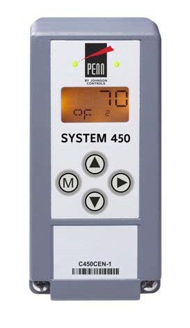
C450CEN Control Module with Communication
- Differential control enables your control system to monitor and maintain a temperature, pressure, or humidity differential between two sensor points within a system, process, or space.
- Ethernet communication capability through a built-in web server (Ethernet control modules only) allows you to monitor your control system status and set up or change the parameters by means of a direct Ethernet cable connection, through a LAN connection, or over the Internet. The built in web server delivers user-friendly web pages to client browsers on a desktop, laptop, tablet, or smart device.
- The web page server on Ethernet communication modules provides a simple, intuitive web interface for easy remote monitoring, setup, adjustment and remote monitoring of your control systems across Ethernet networks.
- RS485, RTU-compliant Modbus® network communication capability (Modbus control modules only) enables a head-end RS485 Modbus master controller to read and write control system status and setup parameters to the System 450 Modbus communication control module.
- Password protection for local access (Ethernet and Modbus control modules only) and password protection for remote access (Ethernet control module only) deters unauthorized changes to the control system settings, but allows local and remote monitoring of your control system status.
- Analog output signal limiting features (communication control modules only) allow you to select the rate and condition range at which the control updates the analog output signal, potentially reducing wear on the controlled equipment.
- Binary input with time delay (communication control modules only) allows you to use an external set of dry contacts and selectable time delays to control relay outputs.
System 450 Control Series
![]() System 450™ Series Control Module with Network Communications (Continued)
System 450™ Series Control Module with Network Communications (Continued)
![]()
![]()
![]()
Selection Chart
Refer to the System 450 Compatible Sensors, Transducers, and Accessories Catalog Page (LIT-1900662) for temperature sensors, humidity sensors, and pressure transducers compatible with the System 450 Control Modules.
Communications System 450 Modules and Accessories Ordering Information
Repair Information
If the System 450™ Control Module with Ethernet or RS485 Modbus Communication fails to operate within its specifications, replace the unit. For a replacement System 450™ Control Module, contact a Johnson Controls® representative.
Technical Specifications
| C450CEN-1C Control Module with Ethernet Communications | |
| Product | C450CEN: System 450 control modules are sensing controls and operating controls with LCD and four-button
touchpad UI, Ethernet communications capability, and no outputs. C450CEN-1C: Control module with Ethernet communications capability |
| Supply Power | Internal Supply Power: C450YNN-1C Power Supply Module
External Supply Power: 24 VAC (20 to 30 VAC) Safety Extra-Low Voltage (SELV) (Europe), Class 2 (North America), 50/60 Hz, 10 VA minimum Note: A System 450 control module or module assembly can use an internal or an external supply power source, but must not be connected to both simultaneously. |
| Ambient Operating Conditions | Temperature: -40 to 66C (-40 to 150F)
Humidity: Up to 95% RH noncondensing; maximum dew point 29C (85F) |
| Ambient Shipping and Storage Conditions | Temperature: -40 to 80C (-40 to 176F)
Humidity: Up to 95% RH noncondensing; maximum dew point 29C (85F) |
| Input Signal | 0 to 5 VDC; 1,035 ohms at 25C (77F) for an A99 PTC Temperature Sensor |
| Analog Input Accuracy | Resolution: 16 bits |
| Control Construction | Independently mounted control, surface mounted with Lexan® 950 enclosure suitable for DIN rail mounting or direct mounting to a hard, even surface. |
| Dimensions (H x W x D) | 127 x 63 x 63 mm (5 x 2-3/8 x 2-3/8 in.) |
| Weight | C450CEN-1C: 207 g (0.46 lb) |
| Compliance
|
North America: cULus Listed; UL 60730, File E27734; FCC Compliant to CFR47, Part 15, Subpart B, Class B
Industry Canada (IC) Compliant to Canadian ICES-003, Class B limits |
| Europe: CE Mark – Johnson Controls, Inc. declares that this product is in compliance with the essential requirements
and other relevant provisions of the EMC Directive; Low Voltage Directive; CISPR22, class B. |
|
| Australia: Mark: C-Tick Compliant (N1813) | |
System 450 Control Series
![]() System 450™ Series Control Module with Network Communications (Continued)
System 450™ Series Control Module with Network Communications (Continued)
![]()
![]()
![]()
| C450CRN-1C Control Module with RS485 Modbus Communications | |
| Product | C450CRN-1C: System 450 control modules are sensing controls and operating controls with LCD and four-button
touchpad UI and no outputs. This control module is an RS485, RTU compliant Modbus slave device. |
| Supply Power | Internal Supply Power: C450YNN-1C Power Supply Module
External Supply Power: 24 VAC (20 to 30 VAC) Safety Extra-Low Voltage (SELV) (Europe), Class 2 (North America), 50/60 Hz, 10 VA minimum Note: A System 450 control module or module assembly can use an internal or an external supply power source, but must not be connected to both simultaneously. |
| Ambient Operating Conditions | Temperature: -40 to 66C (-40 to 150F)
Humidity: Up to 95% RH noncondensing; maximum dew point 29C (85F) |
| Ambient Shipping and Storage Conditions | Temperature: -40 to 80C (-40 to 176F)
Humidity: Up to 95% RH noncondensing; maximum dew point 29C (85F) |
| Input Signal | 0 to 5 VDC; 1,035 ohm at 25C (77F) for an A99 PTC Temperature Sensor |
| Analog Input Accuracy | Resolution: 16 bit |
| Control Construction | Independently mounted control, surface mounted with Lexan® 950 enclosure suitable for DIN rail mounting or direct mounting to a hard, even surface. |
| Dimensions (H x W x D) | 127 x 63 x 63 mm (5 x 2-3/8 x 2-3/8 in.) |
| Weight | C450CRN-1C: 207 g (0.46 lb) |
| Compliance
|
North America: cULus Listed; UL 60730, File E27734: FCC Compliant to CFR47, Part 15, Subpart B, Class B
Industry Canada (IC) Compliant to Canadian ICES-003, Class B limits |
| Europe: CE Mark – Johnson Controls, Inc. declares that this product is in compliance with the essential requirements
and other relevant provisions of the EMC Directive; Low Voltage Directive; CISPR22, class B |
|
| Australia: Mark: C-Tick Compliant (N1813) | |
System 450 Control Series
![]()
![]()
![]()
![]() System 450™ Reset Control Modules with Real-Time Clock and Relay Output
System 450™ Reset Control Modules with Real-Time Clock and Relay Output
Description
System 450™ is a family of modular, digital electronic controls that is easily assembled and set up to provide reliable temperature, pressure, and humidity control for a wide variety of HVAC/R applications, commercial process applications, and industrial process applications.
System 450 Reset Control Modules provide many of the features of the standard models for temperature and humidity control. In addition, these modules provide setpoint reset, real-time setback scheduling, and run-time balancing (equal run time) capability.
The System 450 control system is designed to replace System 350™ and System 27 control systems, and to provide many additional features and benefits with fewer than twenty model variations.
System 450 control modules provide a field-configurable
out-of-the-box solution. Most System 450 control modules can control temperature, pressure, and humidity systems simultaneously.
A single C450 control module can be set up as a stand-alone control or connected to expansion modules to control up to ten On/Off relay and proportional analog outputs, based on any of the three available inputs.
Refer to the following documents for important product application information:
- System 450™ Series Modular Controls Product Bulletin (LIT-12011458)
- System 450™ Series Modular Control Systems with Reset Control Modules Technical Bulletin (LIT-12011842)
- System 450™ Series Reset Control Modules with Real-Time Clock and Relay Output Installation Instructions (Part No. 24-7664-2888)
Features
- Durable, compact, interchangeable modular components with
plug-together connectors and DIN rail or direct wall mount capability eliminate field wiring between modules and allow you to quickly and easily design, assemble, install, and upgrade your control systems.
- Versatile, multipurpose, field-configurable control modules and expansion modules designed for global use allow you to create a wide variety of application-specific control systems capable of controlling temperature, pressure, or humidity, or all three conditions simultaneously, with only a small suite of module models.
- Up to three hard-wired input sensors and up to ten relay or analog outputs (in any combination) per control system allow you to build complex custom control systems while reducing your control system cost to only the cost of the required components.
- Control Modules with bright backlit LCDs and four-button touch pad user interfaces provide quick, clear, visual status of your
System 450 control system inputs and outputs with the touch of a button and enable you to quickly and easily set up and adjust your control system.
- Multipurpose, all-in-one control modules enable simple stand-alone, single-module control systems that are temperature, pressure, and humidity capable out of the box and easy to set up in the field to replace a wide variety of OEM HVAC/R and process controls.
- An extensive suite of compatible temperature and humidity sensors, and pressure transducers allows you to monitor and control a wide range of HVAC/R and process conditions in a variety of standard and global units of measurement.
- High input signal selection enables your control system to monitor a temperature, pressure, or humidity condition with two or three sensors (of the same type) and control your system outputs based on the highest condition value sensed by the referenced sensors.
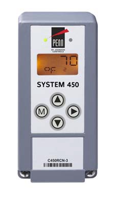
C450RCN-3 Reset Control Module with Real-Time Clock and Relay Output
- Differential control enables your control system to monitor and maintain a temperature, pressure, or humidity differential between two sensor points within a system, process, or space.
Reset Control Features
- Adjustable minimum and maximum setpoint temperatures (reset control modules only) enable compliance with the manufacturer’s specifications for your controlled HVAC/R and process equipment.
- Selectable shutdown-high and shutdown-low temperature settings (reset control modules only) saves you energy by shutting down controlled equipment when the ambient temperature either rises or drops to a point where heating or cooling is no longer required.
- Real time clock and adjustable setback temperature (reset control modules only) save you energy by setting back heating, cooling, or humidity setpoints during scheduled unoccupied periods (24-hour day, 7-day week schedule).
- User-defined reset control capability (reset control modules only) saves you energy in a wide variety of temperature and humidity reset control applications by adjusting the temperature or humidity control loop, based on changes in ambient outdoor temperature or other uncontrolled condition.
Repair Information
If the System 450 Reset Control Module fails to operate within its specifications, replace the unit. For a replacement System 450 Reset Control Module, contact the nearest Johnson Controls® representative.
System 450 Control Series
![]() System 450™ Reset Control Modules with Real-Time Clock and Relay Output (Continued)
System 450™ Reset Control Modules with Real-Time Clock and Relay Output (Continued)
![]()
![]()
![]()
Selection Chart
Refer to the System 450 Compatible Sensors, Transducers, and Accessories Catalog Page (LIT-1900662) for temperature sensors and humidity sensors compatible with the System 450 Reset Control Modules. Reset Control Modules control temperature and humidity, but not pressure.
Reset System 450 Modules and Accessories Ordering Information
Technical Specifications
| C450RBN-3C and C450RCN-3C Reset Control Modules with Real-Time Clock and Relay Output | |
| Product | C450RBN-3C and C450RCN-3C: System 450 Reset Control Module models are sensing controls and operating
controls with LCD, four-button touchpad, and SPDT relay output C450RBN-3C: Control Module with one SPDT output relay C450RCN-3C: Control Module with two SPDT output relays |
| Power Consumption | C450RBN-3C: 0.9 VA maximum C450RCN-3C: 1.3 VA maximum |
| Supply Power | Internal Supply Power: C450YNN-1C Power Supply Module
External Supply Power: 24 VAC (20 to 30 VAC) Safety Extra-Low Voltage (SELV) (Europe), Class 2 (North America), 50/60 Hz, 10 VA minimum Note: A System 450 control module or module assembly can use an internal or an external supply power source, but must not be connected to both simultaneously. |
| Ambient Operating Conditions | Temperature: -40 to 66C (-40 to 150F)
Humidity: Up to 95% RH noncondensing; maximum dew point 29C (85F) |
| Ambient Shipping and Storage Conditions | Temperature: -40 to 80C (-40 to 176F)
Humidity: Up to 95% RH noncondensing; maximum dew point 29C (85F) |
| Input Signal | 0 to 5 VDC for humidity sensors
1,035 ohms at 25C (77F) for A99 PTC temperature sensors |
| Output Relay Contacts | General: 1/2 HP at 120/240 VAC, SPDT |
| Specific: AC Motor Ratings 120 VAC 208/240 VAC AC Full-load Amperes: 9.8 A 4.9 A AC Locked-Rotor Amperes: 58.8 A 29.4 A
10 Amperes AC Non-inductive at 24/240 VAC Pilot Duty: 125 VA at 24/240 VAC |
|
| Clock Accuracy | ±4 minutes per year |
| Clock Backup Power | 12 hours (capacitor reserve) |
| Setback Events | One occupied and one unoccupied event per day; 7 day schedule |
| Analog Input Accuracy | Resolution: 14 bits |
| Control Construction | Independently mounted control, surface mounted with Lexan® 950 enclosure suitable for DIN rail mounting or direct mounting to a hard, even surface. |
| Dimensions (H x W x D) | 127 x 61 x 61 mm (5 x 2-3/8 x 2-3/8 in.) |
| Weight | C450RBN-3C: 209 g (0.46 lb)
C450RCN-3C: 222 g (0.49 lb) |
| Compliance
|
North America: cULus Listed; UL 60730, File E27734; FCC Compliant to CFR47, Part 15, Subpart B, Class B;
Industry Canada (IC) Compliant to Canadian ICES-003, Class B limits |
| Europe: CE Mark – Johnson Controls, Inc. declares that this product is in compliance with the essential
requirements and other relevant provisions of the EMC Directive and the Low Voltage Directive. |
|
| Australia: Mark: C-Tick Compliant (N1813) | |
![]()
![]()
![]()
Code No. LIT-1900656
System 450™ Control Modules with Analog Output
![]()
Description
System 450™ is a family of modular, digital electronic controls that is easily assembled and set up to provide reliable temperature, pressure, and humidity control for a wide variety of HVAC/R applications, commercial process applications, and industrial process applications.
The System 450 control system is designed to replace System 350™ and System 27 control systems, and to provide many additional features and benefits with fewer than twenty model variations.
System 450 control modules provide a field-configurable out-of-the-box solution. Most System 450 control modules can control temperature, pressure, and humidity systems simultaneously.
A single C450 control module can be set up as a stand-alone control or connected to expansion modules to control up to ten On/Off relay and proportional analog outputs, based on any of the three available inputs.
Refer to the following documents for important product application information:
- System 450™ Series Modular Controls Product Bulletin (LIT-12011458)
- System 450™ Series Modular Control Systems with Standard Control Modules Technical Bulletin (LIT-12011459)
- System 450™ Series Control Modules with Analog Outputs Installation Instructions (Part No. 24-7664-2853)
Features
- Durable, compact, interchangeable modular components with
plug-together connectors and DIN rail or direct wall mount capability eliminate field wiring between modules and allow you to quickly and easily design, assemble, install, and upgrade your control systems.
- Versatile, multipurpose, field-configurable control modules and expansion modules designed for global use allow you to create a wide variety of application-specific control systems capable of controlling temperature, pressure, or humidity, or all three conditions simultaneously, with only a small suite of module models.
- Up to three hard-wired input sensors and up to ten relay or analog outputs (in any combination) per control system allow you to build complex custom control systems while reducing your control system cost to only the cost of the required components.
- Control Modules with bright backlit LCDs and four-button touch pad user interfaces provide quick, clear, visual status of your
System 450 control system inputs and outputs with the touch of a button and enable you to quickly and easily set up and adjust your control system.
Selection Chart
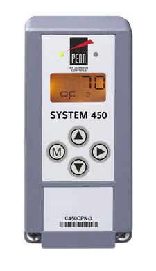
C450CPN-3C Control Module with Analog Output
- Multipurpose, all-in-one control modules enable simple
stand-alone, single-module control systems that are temperature, pressure, and humidity capable out of the box and easy to set up in the field to replace a wide variety of OEM HVAC/R and process controls.
- An extensive suite of compatible temperature and humidity sensors, and pressure transducers allows you to monitor and control a wide range of HVAC/R and process conditions in a variety of standard and global units of measurement.
- High input signal selection enables your control system to monitor a temperature, pressure, or humidity condition with two or three sensors (of the same type) and control your system outputs based on the highest condition value sensed by the referenced sensors.
- Differential control enables your control system to monitor and maintain a temperature, pressure, or humidity differential between two sensor points within a system, process, or space.
Repair Information
If the System 450™ Control Module with Analog Outputs fails to operate within its specifications, replace the unit. For a replacement System 450™ Control Module with Analog Outputs, contact your Johnson Controls® representative.
Refer to the System 450 Compatible Sensors, Transducers, and Accessories Catalog Page (LIT-1900662) for temperature sensors, humidity sensors, and pressure transducers compatible with the System 450 Control Modules with Analog Outputs.
Standard System 450 Modules and Accessories Ordering Information
System 450 Control Series
System 450™ Control Modules with Analog Output (Continued)
![]()
![]()
![]()
![]()
Technical Specifications
| C450CPN-3C and C450CQN-3C Control Modules with Analog Output | |
| Product | C450CPN-3C and C450CQN-3C: System 450 Control Module models are sensing controls and operating controls
with LCD, four-button touchpad, and SPDT analog output C450CPN-3C: Control Module with one analog output C450CQN-3C: Control Module with two analog outputs |
| Power Consumption | C450CPN-3C: 1.3 VA maximum using 0 to 10 V out; 1.5 VA maximum using 4 to 20 mA out
C450CQN-3C: 2.0 VA maximum using 0 to 10 V out; 2.4 VA maximum using 4 to 20 mA out |
| Supply Power | Internal Supply Power: C450YNN-1C Power Supply Module
External Supply Power: 24 VAC (20 to 30 VAC) Safety Extra-Low Voltage (SELV) (Europe), Class 2 (North America), 50/60 Hz, 10 VA minimum Note: A System 450 control module or module assembly can use an internal or an external supply power source, but must not be connected to both simultaneously. |
| Ambient Operating Conditions | Temperature: -40 to 66C (-40 to 150F) when using 0 to 10 VDC outputs;
-40 to 40C (-40 to 104F) when using 4 to 20 mA outputs Humidity: Up to 95% RH noncondensing; maximum dew point 29C (85F) |
| Ambient Shipping and Storage Conditions | Temperature: -40 to 80C (-40 to 176F)
Humidity: Up to 95% RH noncondensing; maximum dew point 29C (85F) |
| Input Signal | 0 to 5 VDC for humidity sensors and static pressure transducers
0.5 to 4.5 VDC for ratiometric pressure transducers 1,035 ohms at 25C (77F) for A99 PTC temperature sensors 1,000 ohms at 21.1C (70F) for TE-6xxx Nickel temperature sensors |
| Analog Output | Voltage Mode (0–10 VDC):
10 VDC maximum output voltage 10 mA maximum output current Requires an external load of 1,000 ohms or more The AO operates in Voltage Mode when connected to devices with impedance greater than 1,000 ohms. Devices that fall below 1,000 ohms may not operate as intended with Voltage Mode applications. |
| Current Mode (4–20 mA):
Requires an external load between 0 to 300 ohms The AO operates in Current Mode when connected to devices with impedance less than 300 ohms. Devices that rise above 300 ohms may not operate as intended with Current Mode applications. |
|
| Analog Input Accuracy | Resolution: 14 bits |
| Control Construction | Independently mounted control, surface mounted with Lexan® 950 enclosure suitable for DIN rail mounting or direct mounting to a hard, even surface. |
| Dimensions (H x W x D) | 127 x 61 x 61 mm (5 x 2-3/8 x 2-3/8 in.) |
| Weight | C450CPN-3C: 195 g (0.43 lb)
C450CQN-3C: 195 g (0.43 lb) |
| Compliance
|
North America: cULus Listed; UL 60730, File E27734; FCC Compliant to CFR47, Part 15, Subpart B, Class B
Industry Canada (IC) Compliant to Canadian ICES-003, Class B limits |
| Europe: CE Mark – Johnson Controls, Inc. declares that this product is in compliance with the essential
requirements and other relevant provisions of the EMC Directive and the Low Voltage Directive. |
|
| Australia: Mark: C-Tick Compliant (N1813) | |
![]()
![]()
![]()
System 450 Control Series
System 450™ Control Modules with Relay Output
![]()
Description
System 450™ is a family of modular, digital electronic controls that is easily assembled and set up to provide reliable temperature, pressure, and humidity control for a wide variety of HVAC/R applications, commercial process applications, and industrial process applications.
The System 450 control system is designed to replace System 350™ and System 27 control systems, and to provide many additional features and benefits with fewer than twenty model variations.
System 450 control modules provide a field-configurable out-of-the-box solution. Most System 450 control modules can control temperature, pressure, and humidity systems simultaneously.
A single C450 control module can be set up as a stand-alone control or connected to expansion modules to control up to ten On/Off relay and proportional analog outputs, based on any of the three available inputs.
Refer to the following documents for important product application information:
- System 450™ Series Modular Controls Product Bulletin (LIT-12011458)
- System 450™ Series Modular Control Systems with Standard Control Modules Technical Bulletin (LIT-12011459)
- System 450™ Series Control Modules with Relay Outputs Installation Instructions (Part No. 24-7664-2896)
Features
- Durable, compact, interchangeable modular components with
plug-together connectors and DIN rail or direct wall mount capability eliminate field wiring between modules and allow you to quickly and easily design, assemble, install, and upgrade your control systems.
- Versatile, multipurpose, field-configurable control modules and expansion modules designed for global use allow you to create a wide variety of application-specific control systems capable of controlling temperature, pressure, or humidity, or all three conditions simultaneously, with only a small suite of module models.
- Up to three hard-wired input sensors and up to ten relay or analog outputs (in any combination) per control system allow you to build complex custom control systems while reducing your control system cost to only the cost of the required components.
- Control Modules with bright backlit LCDs and four-button touch pad user interfaces provide quick, clear, visual status of your
System 450 control system inputs and outputs with the touch of a button and enable you to quickly and easily set up and adjust your control system.
Selection Chart
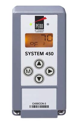
C450CCN-3C Control Module with Relay Output
- Multipurpose, all-in-one control modules enable simple stand-alone, single-module control systems that are temperature, pressure, and humidity capable out of the box and are easy to set up in the field to replace a wide variety of OEM HVAC/R and process controls.
- An extensive suite of compatible temperature and humidity sensors and pressure transducers allows you to monitor and control a wide range of HVAC/R and process conditions in a variety of standard and global units of measurement.
- High input signal selection enables your control system to monitor a temperature, pressure, or humidity condition with two or three sensors (of the same type) and control your system outputs based on the highest condition value sensed by the referenced sensors.
- Differential control enables your control system to monitor and maintain a temperature, pressure, or humidity differential between two sensor points within a system, process, or space.
Repair Information
If the System 450™ Control Module with Relay Outputs fails to operate within its specifications, replace the unit. For a replacement System 450™ Control Module with Relay Outputs, contact a Johnson Controls® representative.
Refer to the System 450 Compatible Sensors, Transducers, and Accessories Catalog Page (LIT-1900662) for temperature sensors, humidity sensors, and pressure transducers compatible with the System 450 Control Modules with Relay Outputs.
Standard System 450 Modules and Accessories Ordering Information
System 450 Control Series
System 450™ Control Modules with Relay Output (Continued)
![]()
![]()
![]()
![]()
Technical Specifications
| C450CBN-3C and C450CCN-3C Control Modules with Relay Output | |
| Product | C450CBN-3C and C450CCN-3C: System 450 Control Module models are sensing controls and operating controls
with LCD, four-button touchpad, and SPDT relay output C450CBN-3C: Control Module with one SPDT output relay C450CCN-3C: Control Module with two SPDT output relays |
| Power Consumption | C450CBN-3C: 0.9 VA maximum C450CCN-3C: 1.3 VA maximum |
| Supply Power | Internal Supply Power: C450YNN-1C Power Supply Module
External Supply Power: 24 VAC (20 to 30 VAC) Safety Extra-Low Voltage (SELV) (Europe), Class 2 (North America), 50/60 Hz, 10 VA minimum Note: A System 450 control module or module assembly can use an internal or an external supply power source, but must not be connected to both simultaneously. |
| Ambient Operating Conditions | Temperature: -40 to 66C (-40 to 150F)
Humidity: Up to 95% RH noncondensing; maximum dew point 29C (85F) |
| Ambient Shipping and Storage Conditions | Temperature: -40 to 80C (-40 to 176F)
Humidity: Up to 95% RH noncondensing; maximum dew point 29C (85F) |
| Input Signal | 0 to 5 VDC for humidity sensors and static pressure transducers
0.5 to 4.5 VDC for ratiometric pressure transducers 1,035 ohms at 25C (77F) for A99 PTC temperature sensors 1,000 ohms at 21.1C (70F) for TE-6xxx Nickel temperature sensors |
| Output Relay Contacts | General: 1/2 HP at 120/240 VAC, SPDT |
| Specific: AC Motor Ratings 120 VAC 208/240 VAC AC Full-load Amperes: 9.8 A 4.9 A Locked-Rotor Amperes: 58.8 A 29.4 A
10 Amperes AC Non-inductive at 24/240 VAC Pilot Duty: 125 VA at 24/240 VAC |
|
| Analog Input Accuracy | Resolution: 14 bits |
| Control Construction | Independently mounted control, surface mounted with Lexan® 950 enclosure suitable for DIN rail mounting or direct mounting to a hard, even surface. |
| Dimensions (H x W x D) | 127 x 61 x 61 mm (5 x 2-3/8 x 2-3/8 in.) |
| Weight | C450CBN-3C: 209 g (0.46 lb)
C450CCN-3C: 222 g (0.49 lb) |
| Compliance
|
North America: cULus Listed; UL 60730, File E27734; FCC Compliant to CFR47, Part 15, Subpart B, Class B;
Industry Canada (IC) Compliant to Canadian ICES-003, Class B limits |
| Europe: CE Mark – Johnson Controls, Inc. declares that this product is in compliance with the essential
requirements and other relevant provisions of the EMC Directive and the Low Voltage Directive. |
|
| Australia: Mark: C-Tick Compliant (N1813) | |
![]()
![]()
![]()
System 450 Control Series
System 450™ Control Module with Hybrid Analog Output
![]()
Description
System 450™ is a family of modular, digital electronic controls that is easily assembled and set up to provide reliable temperature, pressure, and humidity control for a wide variety of HVAC/R applications, commercial process applications, and industrial process applications.
System 450 control modules provide a field-configurable out-of-the-box solution. Most System 450 control modules can control temperature, pressure, and humidity systems simultaneously.
A single C450 control module can be set up as a stand-alone control or connected to expansion modules to control up to ten On/Off relay and proportional analog outputs, based on any of the three available inputs.
The System 450 Control Module with Hybrid Analog Output has a single self-selecting analog output to optimize and extend the controlled speed range of variable speed electronically commutated (EC) motors.
Refer to the following documents for important product application information:
- System 450™ Series Modular Controls Product Bulletin (LIT-12011458)
- System 450™ Series Modular Control Systems with Standard Control Modules Technical Bulletin (LIT-12011459)
- System 450™ Series Control Module with Hybrid Analog Output and High Input Signal Selection Installation Instructions
(Part No. 24-7664-2802)
Features
- Durable, compact, interchangeable modular components with
plug-together connectors and DIN rail or direct wall mount capability eliminate field wiring between modules and allow you to quickly and easily design, assemble, install, and upgrade your control systems.
- Versatile, multipurpose, field-configurable control modules and expansion modules designed for global use allow you to create a wide variety of application-specific control systems capable of controlling temperature, pressure, or humidity, or all three conditions simultaneously, with only a small suite of module models.
- Up to three hard-wired input sensors and up to ten relay or analog outputs (in any combination) per control system allow you to build complex custom control systems while reducing your control system cost to only the cost of the required components.
- Control Modules with bright backlit LCDs and four-button touch pad user interfaces provide quick, clear, visual status of your
System 450 control system inputs and outputs with the touch of a button and enable you to quickly and easily set up and adjust your control system.
- Multipurpose, all-in-one control modules enable simple stand-alone, single-module control systems that are temperature, pressure, and humidity capable out of the box and easy to set up in the field to replace a wide variety of OEM HVAC/R and process controls.
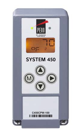
C450CPW-100 Control Module with Hybrid Analog Output
- An extensive suite of compatible temperature and humidity sensors, and pressure transducers allows you to monitor and control a wide range of HVAC/R and process conditions in a variety of standard and global units of measurement.
- High input signal selection enables your control system to monitor a temperature, pressure, or humidity condition with two or three sensors (of the same type) and control your system outputs based on the highest condition value sensed by the referenced sensors.
- Differential control enables your control system to monitor and maintain a temperature, pressure, or humidity differential between two sensor points within a system, process, or space.
Repair Information
If the System 450™ Control Module with Hybrid Analog Output fails to operate within its specifications, replace the unit. For a replacement System 450™ Control Module with Hybrid Analog Output, contact a Johnson Controls® representative.
System 450 Control Series
System 450™ Control Module with Hybrid Analog Output (Continued)
![]()
![]()
![]()
![]()
Selection Chart
Refer to the System 450 Compatible Sensors, Transducers, and Accessories Catalog Page (LIT-1900662) for temperature sensors, humidity sensors, and pressure transducers compatible with the System 450 Control Modules.
Hybrid System 450 Modules and Accessories Ordering Information
Technical Specifications
| C450CPW-100C Control Module with Hybrid Analog Output | |
| Product | C450CPW-100C System 450 control module is a sensing control and operating control with LCD, four-button
touchpad, and analog output with pulse-width modulation capability. |
| Power Consumption | C450CPW-100C: 1.3 VA maximum using 0 to 10 V out; 1.5 VA maximum using 4 to 20 mA out |
| Supply Power | Internal Supply Power: C450YNN-1C Power Supply Module
External Supply Power: 24 VAC (20–30 VAC) Safety Extra-Low Voltage (SELV) (Europe), Class 2 (North America), 50/ 60 Hz, 10 VA minimum Note: A System 450 control module or module assembly can use an internal or an external supply power source, but must not be connected to both simultaneously. |
| Ambient Operating Conditions | Temperature: -40 to 66C (-40 to 150F) when using 0 to 10 VDC outputs;
-40 to 40C (-40 to 104F) when using 4 to 20 mA outputs Humidity: Up to 95% RH noncondensing; maximum dew point 29C (85F) |
| Ambient Shipping and Storage Conditions | Temperature: -40 to 80C (-40 to 176F)
Humidity: Up to 95% RH noncondensing; maximum dew point 29C (85F) |
| Input Signal | 0 to 5 VDC for humidity sensors and static pressure transducers
0.5 to 4.5 VDC for ratiometric pressure transducers 1,035 ohms at 25C (77F) for A99 PTC temperature sensors 1,000 ohms at 21.1C (70F) for TE-6xxx Nickel temperature sensors |
| Analog Output | Voltage Mode (0–10 VDC):
10 VDC maximum output voltage 10 mA maximum output current Requires an external load of 1,000 ohms or more The AO operates in Voltage Mode when connected to devices with impedance greater than 1,000 ohms. Devices that fall below 1,000 ohms may not operate as intended with Voltage Mode applications. |
| Current Mode (4–20 mA):
Requires an external load between 0 to 300 ohms The AO operates in Current Mode when connected to devices with impedance less than 300 ohms. Devices that rise above 300 ohms may not operate as intended with Current Mode applications. |
|
| Analog Input Accuracy | Resolution: 14 bits |
| Control Construction | Independently mounted control, surface mounted with Lexan® 950 enclosure suitable for DIN rail mounting or direct mounting to a hard, even surface. |
| Dimensions (H x W x D) | 127 x 61 x 61 mm (5 x 2-3/8 x 2-3/8 in.) |
| Weight | C450CPW-100C: 195 g (0.43 lb) |
| Compliance
|
North America: cULus Listed; UL 60730, File E27734; FCC Compliant to CFR47, Part 15, Subpart B, Class B
Industry Canada (IC) Compliant to Canadian ICES-003, Class B limits |
| Europe: CE Mark – Johnson Controls, Inc. declares that this product is in compliance with the essential requirements
and other relevant provisions of the EMC Directive and the Low Voltage Directive. |
|
| Australia: Mark: C-Tick Compliant (N1813) | |
![]()
![]()
![]()
System 450 Control Series
System 450™ Expansion Modules with Analog Output
![]()
Description
System 450 expansion modules allow you to increase the number of outputs in your control system to meet your application requirements. The following models are available:
- C450SPN-1C: Analog Expansion Module with one analog output (each 0 to 10 VDC or 4 to 20 mA)
- C450SQN-1C: Analog Expansion Module with two analog outputs (each 0 to 10 VDC or 4 to 20 mA)
Refer to the following documents for important product application information:
- System 450™ Series Modular Controls Product Bulletin (LIT-12011458)
- System 450™ Series Expansion Modules with Analog Outputs Installation Instructions (Part No. 24-7664-2799)
Features
- Durable, compact, interchangeable modular components with
plug-together connectors and DIN rail or direct wall mount capability eliminate field wiring between modules and allow you to quickly and easily design, assemble, install, and upgrade your control systems.
- Versatile, multipurpose, field-configurable control modules and expansion modules designed for global use allow you to create a wide variety of application-specific control systems capable of controlling temperature, pressure, or humidity, or all three conditions simultaneously, with only a small suite of module models.
- Up to three hard-wired input sensors and up to ten relay or analog outputs (in any combination) per control system allow you to build complex custom control systems while reducing your control system cost to only the cost of the required components.
Selection Chart
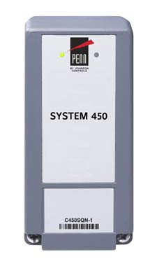
C450SQN-1C Expansion Module with Analog Output
Repair Information
If the System 450™ Expansion Module with Analog Output fails to operate within its specifications, replace the unit. For a replacement System 450™ Expansion Module with Analog Output, contact a Johnson Controls® representative.
System 450 Control Series
System 450™ Expansion Modules with Analog Output (Continued)
![]()
![]()
![]()
![]()
Technical Specifications
| C450SPN-1C and C450SQN-1C Expansion Modules with Analog Output | |
| Product | C450SPN-1C: System 450 Expansion Module with one analog output
C450SQN-1C: System 450 Expansion Module with two analog outputs |
| Power Consumption | C450SPN-1C: 1.1 VA maximum using 0 to 10 V out; 1.3 VA maximum using 4 to 20 mA out
C450SQN-1C: 1.8 VA maximum using 0 to 10 V out; 2.2 VA maximum using 4 to 20 mA out |
| Supply Power | Internal Supply Power: C450YNN-1C Power Supply Module
External Supply Power: 24 VAC (20 to 30 VAC) Safety Extra-Low Voltage (SELV) (Europe), Class 2 (North America), 50/60 Hz, 10 VA minimum Note: A System 450 control module or module assembly can use an internal or an external supply power source, but must not be connected to both simultaneously. |
| Ambient Operating Conditions | Temperature: -40 to 66C (-40 to 150F) when using 0 to 10 VDC outputs;
-40 to 40C (-40 to 104F) when using 4 to 20 mA outputs Humidity: Up to 95% RH noncondensing; maximum dew point 29C (85F) |
| Ambient Shipping and Storage Conditions | Temperature: -40 to 80C (-40 to 176F)
Humidity: Up to 95% RH noncondensing; maximum dew point 29C (85F) |
| Analog Output | Voltage Mode (0 to 10 VDC):
10 VDC maximum output voltage 10 mA maximum output current Requires an external load of 1,000 ohms or more The AO operates in Voltage Mode when connected to devices with impedance greater than 1,000 ohms. Devices that drop below 1,000 ohms may not operate as intended with Voltage Mode applications. |
| Current Mode (4 to 20 mA):
Requires an external load between 0 to 300 ohms The AO operates in Current Mode when connected to devices with impedances less than 300 ohm. Devices that exceed 300 ohms may not operate as intended with Current Mode applications. |
|
| Control Construction | Independently mounted control, surface mounted with Lexan® 950 enclosure suitable for DIN rail mounting or direct mounting to a hard, even surface. |
| Dimensions (H x W x D) | 127 x 61 x 61 mm (5 x 2-3/8 x 2-3/8 in.) |
| Weight | C450SPN-1C: 150 g (0.33 lb)
C450SQN-1C: 150 g (0.33 lb) |
| Compliance
|
North America: cULus Listed; UL 60730, File E27734, Vol. 1; FCC Compliant to CFR47, Part 15, Subpart B, Class B Industry Canada (IC) Compliant to Canadian ICES-003, Class B limits |
| Europe: CE Mark – Johnson Controls, Inc., declares that this product is in compliance with the essential requirements
and other relevant provisions of the Low Voltage Directive and the EMC Directive. |
|
| Australia: Mark: C-Tick Compliant (N1813) | |
![]()
![]()
![]()
System 450 Control Series
System 450™ Expansion Modules with Relay Output
![]()
Description
System 450 expansion modules allow you to increase the number of outputs in your control system to meet your application requirements. The following models are available:
- C450SBN-3C: Relay Expansion Module with one relay output
- C450SCN-3C: Relay Expansion Module with two relay outputs
Refer to the following documents for important product application information:
- System 450™ Series Modular Controls Product Bulletin (LIT-12011458)
- System 450™ Series Expansion Modules with Relay Outputs Installation Instructions (Part No. 24-7664-2896)
Features
- Durable, compact, interchangeable modular components with
plug-together connectors and DIN rail or direct wall mount capability eliminate field wiring between modules and allow you to quickly and easily design, assemble, install, and upgrade your control systems.
- Versatile, multipurpose, field-configurable control modules and expansion modules designed for global use allow you to create a wide variety of application-specific control systems capable of controlling temperature, pressure, or humidity, or all three conditions simultaneously, with only a small suite of module models.
- Up to three hard-wired input sensors and up to ten relay or analog outputs (in any combination) per control system allow you to build complex custom control systems while reducing your control system cost to only the cost of the required components.
Selection Chart

C450SCN-3C Expansion Module with Relay Output
Repair Information
If the System 450™ Expansion Module with Relay Output fails to operate within its specifications, replace the unit. For a replacement System 450™ Expansion Module with Relay Output, contact a Johnson Controls® representative.
System 450 Control Series
System 450™ Expansion Modules with Relay Output (Continued)
![]()
![]()
![]()
![]()
Technical Specifications
| C450SBN-3C and C450SCN-3C Expansion Modules with Relay Output | |
| Product | C450SBN-3C: System 450 Expansion Module with one SPDT output relay
C450SCN-3C: System 450 Expansion Module with two SPDT output relays |
| Power Consumption | C450SBN-3C: 0.8 VA maximum C450SCN-3C: 1.2 VA maximum |
| Supply Power | Internal Supply Power: C450YNN-1C Power Supply Module
External Supply Power: 24 VAC (20 to 30 VAC) Safety Extra-Low Voltage (SELV) (Europe), Class 2 (North America), 50/60 Hz, 10 VA minimum Note: A System 450 control module or module assembly can use an internal or an external supply power source, but must not be connected to both simultaneously. |
| Ambient Operating Conditions | Temperature: -40 to 66C (-40 to 150F)
Humidity: Up to 95% RH noncondensing; maximum dew point 29C (85F) |
| Ambient Shipping and Storage Conditions | Temperature: -40 to 80C (-40 to 176F)
Humidity: Up to 95% RH noncondensing; maximum dew point 29C (85F) |
| Output Relay Contacts | General: 1/2 HP at 120/240 VAC, SPDT |
| Specific: AC Motor Ratings 120 VAC 208/240 VAC AC Full-Load Amperes: 9.8 A 4.9 A
AC Locked-Rotor Amperes: 58.8 A 29.4 A 10 Amperes AC Noninductive at 24/240 VAC Pilot Duty: 125 VA at 24/240 VAC |
|
| Control Construction | Independently mounted control, surface mounted with Lexan® 950 enclosure suitable for DIN rail mounting or direct mounting to a hard, even surface. |
| Dimensions (H x W x D) | 127 x 61 x 61 mm (5 x 2-3/8 x 2-3/8 in.) |
| Weight | C450SBN-3C: 172 g (0.38 lb)
C450SCN-3C: 186 g (0.41 lb) |
| Compliance
|
North America: cULus Listed; UL 60730, File E27734; FCC Compliant to CFR47, Part 15, Subpart B, Class B
Industry Canada (IC) Compliant to Canadian ICES-003, Class B limits |
| Europe: CE Mark – Johnson Controls, Inc. declares that this product is in compliance with the essential requirements and
other relevant provisions of the EMC Directive and the Low Voltage Directive. |
|
| Australia: Mark: C-Tick Compliant (N1813) | |
![]()
Description
![]()
![]()
![]()
System 450 Control Series
Code No. LIT-1900661
System 450™ Power Module
System 450™ modules require 24 VAC, Class 2 power. In applications where 24 VAC power is not available, the C450YNN-1C Power Module provides a convenient modular solution for transforming 120/240 VAC to 24 VAC power for your System 450 control systems.
Refer to the following documents for important product application information:
- System 450™ Series Modular Controls Product Bulletin (LIT-12011458)
- System 450™ Series Power Module Installation Instructions (Part No. 24-7664-2691)
Features
- Durable, compact, interchangeable modular components with
plug-together connectors and DIN rail or direct wall mount capability eliminate field wiring between modules and allow you to quickly and easily design, assemble, install, and upgrade your control systems.
Repair Information
If the System 450 Power Module fails to operate within its specifications, replace the unit. For a replacement System 450 Power Module, contact a Johnson Controls® representative.
Selection Chart
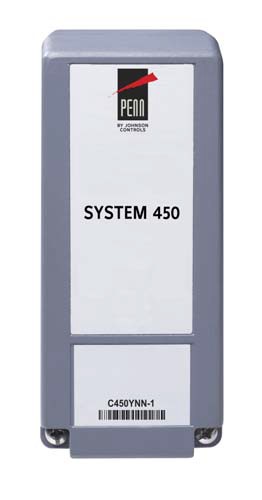
Technical Specifications
| C450YNN-1C Power Supply Module | |
| Product | C450YNN-1C: System 450 Power Supply Module; 120 or 240 VAC stepdown to 24 VAC Class 2 (North America) or
SELV (Europe) |
| Supply Power | 110/120 VAC or 220/240 VAC at 50/60 Hz (100 mA maximum) |
| Secondary Power | 24 VAC, 10 VA |
| Ambient Operating Conditions | Temperature: -40 to 66C (-40 to 150F)
Humidity: Up to 95% RH noncondensing; maximum dew point 29C (85F) |
| Ambient Shipping and Storage Conditions | Temperature: -40 to 80C (-40 to 176F)
Humidity: Up to 95% RH noncondensing; maximum dew point 29C (85F) |
| Control Construction | Independently mounted control, surface mounted with Lexan® 950 enclosure suitable for DIN rail mounting or direct mounting to a hard, even surface. |
| Dimensions (H x W x D) | 127 x 61 x 61 mm (5 x 2-3/8 x 2-3/8 in.) |
| Weight | C450YNN-1C: 390 gm (0.86 lb) |
| Compliance
|
North America: cULus Listed; UL 60730, File E27734: FCC Compliant to CFR47, Part 15, Subpart B, Class B
Industry Canada (IC) Compliant to Canadian ICES-003, Class B limits |
| Europe: CE Mark – Johnson Controls, Inc. declares that this product is in compliance with the essential requirements
and other relevant provisions of the EMC Directive and the Low Voltage Directive. |
|
| Australia: Mark: C-Tick Compliant (N1813) | |
![]()
![]()
![]()
System 450 Control Series
System 450™ Compatible Sensors, Transducers, and Accessories
![]()
Description
System 450 control modules are designed to operate with a variety of compatible sensors and transducers. The System 450 compatible sensors and transducers cover a wide range of temperature, pressure, and humidity conditions, allowing you to select the sensor or transducer that best fits your control system requirements.
For ease of installation and setup, the Sensor Type that you select in the UI for a sensor or transducer automatically determines the sensed condition, unit of measurement, minimum differential, setup value ranges, and the default setup values for each control system output that references the sensor or transducer.
Refer to the System 450™ Series Modular Controls Product Bulletin (LIT-12011458) for important product application information on System 450 Controls.
Refer to the following documents for important product application information on sensors used with System 450 Controls:
- A99B Series Temperature Sensors Product Technical Bulletin (LIT-125186)
- TrueRH™ Series HE-67xx Humidity Element with Temperature Sensors Product Bulletin (LIT-216245)
- HE-6800 Series Humidity Transmitters with Temperature Sensor Product Bulletin (LIT-12011625)
- P499 Series Electronic Pressure Transducers Product/Technical Bulletin (LIT-12011190)
- TE-6000 Series Temperature Sensing Elements Product Bulletin (LIT-216288)
- TE-6300 Series Temperature Sensors Product Bulletin (LIT-216320)
- TE-6800 Series Temperature Sensors Product Bulletin (LIT-12011542)
- Setra Systems Model DPT265 Very Low Differential Pressure Transducer Catalog Page
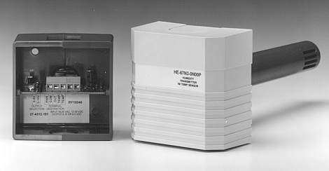
Duct-Mount HE67S3 Humidity Sensor
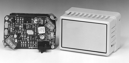
Wall-Mount HE67S3 Humidity Sensor
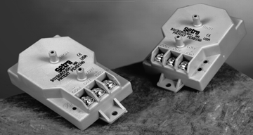
DPT265 Series Low Pressure Differential Pressure Transducers
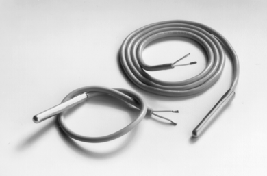
A99 Temperature Sensors
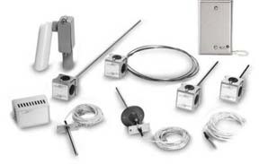
TE-6300 Series Temperature Sensors
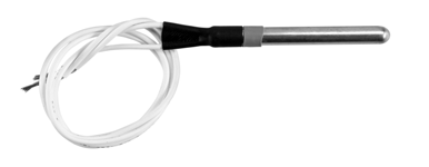
TE-6000-1 Temperature Sensing Element
System 450 Control Series
![]() System 450™ Compatible Sensors, Transducers, and Accessories (Continued)
System 450™ Compatible Sensors, Transducers, and Accessories (Continued)
![]()
![]()
![]()
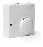
TE-6800 Series Wall Mount Temperature Sensors and HE-6800 Series Humidity Transmitters
with Temperature Sensors
Selection Charts
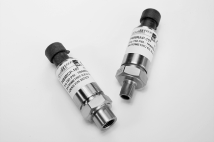 P499 Series Electronic Pressure Transducers
Use these tables to order System 450 compatible sensors, transducers, and accessories.
System 450 Compatible A99B Temperature Sensors and Accessories Ordering Information1
1. Refer to the A99B Series Temperature Sensors Product/Technical Bulletin (LIT-125186) on the Johnson Controls® Product Literature website for more information.
System 450 Compatible TE-6000 Series 1,000 Ohm Nickel Temperature Sensors and Accessories Ordering Information
System 450 Compatible TE-6300 Series 1,000 Ohm Nickel Temperature Sensors and Accessories Ordering Information
System 450 Control Series
![]() System 450™ Compatible Sensors, Transducers, and Accessories (Continued)
System 450™ Compatible Sensors, Transducers, and Accessories (Continued)
![]()
![]()
![]()
System 450 Compatible TE-68NT-0N00S 1,000 Ohm Nickel Temperature Sensor Ordering Information
System 450 Compatible HE67S3 Type Humidity Sensors with Integral A99B Temperature Sensor Ordering Information1
1. The HE-67S3 sensors require 24 VAC input and must use the 0 to 5 VDC output. Refer to the TrueRH Series HE-67xx Humidity Element with Temperature Sensors Product Bulletin (LIT-216245) on the Johnson Controls Product Literature website for more information, including technical specifications and mounting accessories.
System 450 Compatible HE6800 Series Humidity Transmitters with Temperature Sensor Ordering Information1
1. The HE-6800 transmitters require 24 VAC input and must use the 0 to 5 VDC output. Refer to the HE-6800 Series Humidity Transmitters with Temperature Sensor Product Bulletin (LIT-12011625) on the Johnson Controls Product Literature website for more information, including technical specifications and mounting accessories.
System 450 Compatible Low Pressure Differential Transducer Ordering Information1 2
- Refer to the Setra Systems Model DPT265 Very Low Differential Pressure Transducer Catalog Page on the Johnson Controls Product Literature website for more information.
- The DPT265 sensors require 24 VAC input and must use the 0 to 5 VDC output. Refer to the Setra Systems Model DPT265 Very Low Differential Pressure Transducer Catalog Page on the Johnson Controls Product Literature website for more information.
- Used only with Communications Control Modules.
System 450 Compatible P499 Series Transducers with 1/4 in. SAE 45 Flare Internal Thread with Depressor (Style 47) Ordering Information1
1. The P499 sensors must be powered with the +5 VDC and C terminals and the output is 0.5 to 4.5 VDC. Refer to the P499 Series Electronic Pressure Transducers Product/Technical Bulletin (LIT-12011190) on the Johnson Controls Product Literature website for more information.
System 450 Control Series
![]() System 450™ Compatible Sensors, Transducers, and Accessories (Continued)
System 450™ Compatible Sensors, Transducers, and Accessories (Continued)
![]()
![]()
![]()
System 450 Compatible P499 Series Transducers with 1/8 in. 27 NPT External Thread (Style 49) Ordering Information1
1. The P499 sensors must be powered with the +5 VDC and C terminals and the output is 0.5 to 4.5 VDC. Refer to the P499 Series Electronic Pressure Transducers Product/Technical Bulletin (LIT-12011190) on the Johnson Controls Product Literature website for more information.
WHA-PKD3 Wire Harnesses Ordering Information1
1. Refer to the P499 Series Electronic Pressure Transducers Product/Technical Bulletin (LIT-12011190) on the Johnson Controls Product Literature website for more information.
Cross-Reference Code No. LIT-1900120
 Ranco® Refrigeration Cross-Reference
![]()
![]()
![]()
Temperature Controls (Part 1 of 2)
| Product | # | Range | Differential | Switch | Capillary | Bulb | Cover | Notes |
| Ranco | ETC111000-000 | -30/220F | 1/30F ADJ | SPDT | 96” Lead | 0.5×2 | NEMA 1 | |
| PENN | A419ABC-1C | -30/212F | 1/30F ADJ | SPDT | 78” Lead | 0.5X2 | NEMA 1 | (14) |
| Ranco | 3130-101 | 35/45F | 12F FXD | Open LO | None | 240” | NEMA 1 | |
| PENN | A11B-1C | 35/45F | 12F FXD | Open LO | 48” | 240″ | NEMA 1 | |
| Ranco | 3130-201 | 35/45F | Manual | Open LO | None | 240” | NEMA 1 | |
| PENN | A11A-1C | 35/45F | Manual | Open LO | 48” | 240″ | NEMA 1 | |
| Ranco | 3311-651 | 37F FXD | Manual | Open LO | 180″ | 0.5×4.25 | NEMA 1 | |
| PENN | A70BA-17C | 35/80F ADJ | Manual | Open LO | 72″ | 3/8×3 | NEMA 1 | |
| Ranco | 3311-701 | 30F FXD | 15F FXD | Open LO | 120″ | 3/8×6.5 | NEMA 1 | |
| PENN | A70AA-15C | -10/65F ADJ | 4/40F ADJ | Open LO | 72″ | 3/8×3 | NEMA 1 | |
| Ranco | A22-2237 | 41F FXD | 6F FXD | Open HI | None | 48″ | NEMA 1 | |
| PENN | A11E-6C | 35/45F | 12F FXD | SPDT | 48″ | 240″ | NEMA 1 | |
| Ranco | O10-1010 | 0/55F | 7/55F ADJ | Open LO | None | 48″ | NEMA 1 | |
| PENN | A11B-1C | 35/45F | 12F FXD | Open LO | 48″ | 240″ | NEMA 1 | |
| Ranco | O10-1409 | 0/55F | 3/20F ADJ | Open LO | 72″ | Yes | NEMA 1 | |
| PENN | A19ABA-1C | -30/50F | 5/20F ADJ | Open LO | 72″ | 3/8×4 | NEMA 1 | (1) |
| Ranco | O10-1410 | 25/75F | 3/20F ADJ | Open LO | 72″ | Yes | NEMA 1 | |
| PENN | A19ABA-4C | 20/80F | 3.5/14F ADJ | Open LO | 72″ | 3/8×5 | NEMA 1 | (1) |
| Ranco | O10-1416 | 0/55F | 3/20F ADJ | Open LO | None | 72″ | NEMA 1 | |
| PENN | A11B-1C | 35/45F | 12F FXD | Open LO | 48″ | 240″ | NEMA 1 | |
| Ranco
PENN |
O10-1418
A19BBA-1C |
0/55F
-30/50F |
3/20F ADJ
5/20F ADJ |
Open LO
Open LO |
None
None |
Coiled
Coiled |
NEMA 1
NEMA 1 |
(1) |
| Ranco | O10-1473 | 0/55F | 7/55F ADJ | Open LO | 72″ | Yes | NEMA 1 | |
| PENN | A19ABA-1C | -30/50F | 5/20F ADJ | Open LO | 72″ | 3/8×4 | NEMA 1 | (1) |
| Ranco | O10-1490 | 0/55F | 2F FXD | Open LO | 72″ | Yes | NEMA 1 | |
| PENN | A19ABA-1C | -30/50F | 5/20F ADJ | Open LO | 72″ | 3/8×4 | NEMA 1 | (1) |
| Ranco | O10-1491 | 25/75F | 2F FXD | Open LO | 72″ | Yes | NEMA 1 | |
| PENN | A19ABA-4C | 20/80F | 3.5/14F ADJ | Open LO | 72″ | 3/8×5 | NEMA 1 | (1) |
| Ranco | O10-1802 | 25/75F | 3/20F ADJ | Open LO | None | Coiled | NEMA 1 | |
| PENN | A19BAC-1C | 30/110F | 3.5F FXD | SPDT | None | Coiled | NEMA 1 | (1) |
| Ranco | O10-301 | 30/95F | 2F FXD | Open LO | None | Coiled | NEMA 1 | |
| PENN | A19BAA-5C | 30/110F | 3.5F FXD | Open LO | None | Coiled | NEMA 1 | (1) |
| Ranco | O16-104 | 0/55F | 3/20F ADJ | SPDT | 72″ | Yes | NEMA 1 | |
| PENN | A19ABC-24C | -30/100F | 3/12F ADJ | SPDT | 96″ | 3/8×4 | NEMA 1 | (1) |
| Ranco | O16-111 | 0/55F | 3/20F ADJ | SPDT | None | 72″ | NEMA 1 | |
| PENN | A11E-6C | 35/45F | 12F FXD | SPDT | 48″ | 240″ | NEMA 1 | |
| Ranco | O16-165 | 30/90F | 2.5F FXD | SPDT | None | Coiled | NEMA 1 | |
| PENN | A19BAC-1C | 30/110F | 3.5F FXD | SPDT | None | Coiled | NEMA 1 | (1) |
| Ranco | O16-263 | 0/55F | Manual | SPDT | 72″ | Yes | NEMA 1 | |
| PENN | A19ACC-6C | -30/100F | Manual | SPDT | 72″ | 3/8×4 | NEMA 1 | |
| PENN | A70BA-17C | 35/80F | Manual | Open LO | 72″ | 3/8×3 | NEMA 1 | (12) |
| Ranco | O16-264 | 0/55F | Manual | SPDT | None | 96″ | NEMA 1 | |
| PENN | A11D-1C | 35/45F | Manual | SPDT | 48″ | 240″ | NEMA 1 | |
| PENN | A70BA-18C | 15/55F | Manual | Open LO | None | 240″ | NEMA 1 | (12) |
| Ranco | O16-588 | -15/40F | 1.5F FXD | SPDT | None | 72″ | NEMA 1 | |
| PENN | A11E-6C | 35/45F | 12F FXD | SPDT | 48″ | 240″ | NEMA 1 | (1) |
| PENN | A70AA-16C | 15/55F | 5F FXD | Open LO | None | 240″ | NEMA 1 | |
| Ranco
PENN |
O16-594
A19BBC-2C |
0/55F
-30/100F |
2F FXD
3/12F ADJ |
SPDT
SPDT |
None
None |
Coiled
Coiled |
NEMA 1
NEMA 1 |
(1) |
| Ranco | O16-595 | 50/100F | 3/20F ADJ | SPDT | 96″ | 3/8×6 | NEMA 1 | |
| PENN | A19ABC-4C | 50/130F | 3.5/14F ADJ | SPDT | 96″ | 3/8×5 | NEMA 1 | (1) |
| Ranco | O16-601 | 22.5/47.5F | 2.5F FXD | SPDT | 36″ | 3/8×6 | NEMA 1 | |
| PENN | A19ABC-2C | 20/80F | 3.5/14F ADJ | SPDT | 72″ | 3/8×5 | NEMA 1 | (1) |
| PENN | A70AA-15C | -10/65F ADJ | 10F FXD | Open LO | 72″ | 3/8×3 | NEMA 1 | (12) |
| Ranco | O20-7041 | 0/100F | 6/20F ADJ | DPST Open LO | 96″ | 3/8×6 | NEMA 1 | |
| PENN | A72AA-3C | 50/90F | ADJ | DPST Open LO | 72″ | 11/16×6 3/4 | NEMA 1 | |
| PENN | A72AA-2C | 15/55F | ADJ | DPST Open LO | 72″ | 3/8×3 | NEMA 1 |
Cross-Reference
Ranco® Refrigeration Cross-Reference (Continued)
![]()
![]()
![]()
![]()
Temperature Controls (Part 2 of 2)
| Product | # | Range | Differential | Switch | Capillary | Bulb | Cover | Notes |
| Ranco | O52-6910 | 30/95F | 2F FXD | SPDT | None | Coiled | NEMA 4X | |
| PENN | A19PRC-1C | 30/110F | 3/12F ADJ | SPDT | None | Coiled | NEMA 4X | |
| Ranco | O60-100 | -35/95F | 4/50F ADJ | SPDT | 96″ | 3/8×6 | NEMA 1 | |
| PENN | A19ABC-24C | -30/100F | 3/12F ADJ | SPDT | 96″ | 3/8×4 | NEMA 1 | (1) |
| Ranco | O60-101 | -35/95F | 4/50F ADJ | SPDT | None | Coiled | NEMA 1 | |
| PENN | A19BBC-2C | -30/100F | 3/12F ADJ | SPDT | None | Coiled | NEMA 1 | (1) |
| Ranco | O60-1072 | -15/40F | 3/20F ADJ | Open LO | None | Coiled | NEMA 1 | |
| PENN | A19BBA-1C | -30/50F | 5/20F ADJ | Open LO | None | Coiled | NEMA 1 | (1) |
| Ranco | O60-120 | -35/95F | 4/50F ADJ | SPDT | 240″ | 3/8×6 | NEMA 1 | |
| PENN | A19ABC-36C | -30/100F | 3/12F ADJ | SPDT | 240″ | 3/8×4 | NEMA 1 | (1) |
| Ranco | O60-1408 | -15/40F | 3/20F ADJ | Open LO | 72″ | Yes | NEMA 1 | |
| PENN | A19ABA-1C | -30/50F | 5/20F ADJ | Open LO | 72″ | 3/8×4 | NEMA 1 | (1) |
| Ranco | O60-200 | 95/240F | 6/50F ADJ | SPDT | 96″ | 3/8×6 | NEMA 1 | |
| PENN | A19ABC-12C | 100/240F | 6/24F ADJ | SPDT | 96″ | .29×2.5 | NEMA 1 | (1) |
Defrost/Fan Delay Temperature Controls
| Product | # | Range | Differential | Switch | Capillary | Bulb | Cover | Notes |
| Ranco | F25-107 | 40/75F | 20F FXD | SPDT | 60″ | 3/8×4 | Open | |
| PENN | A19ZBC-2C | 45/85 | 25F ADJ | SPDT | 72″ | 0.3×3.125 | NEMA 1 | (10) |
| Ranco | F25-114 | 43/73F | 24F FXD | SPDT | 60″ | 3/8×4 | Open | |
| PENN | A19ZBC-2C | 45/85 | 25F ADJ | SPDT | 72″ | 0.3×3.125 | NEMA 1 | (10) |
Pressure Controls (Ranco Series 3126-3161, G20-G23, and O10-O20) (Part 1 of 3)
| Product | # | Range | Differential | Switch | Capillary | Connection | Cover | Notes |
| Ranco | 3126-116 | 7/125 | 25 FXD | SPDT | 60″ | Sweat | Open | |
| PENN | P20EB-1C | 7/150 | 29/32 FXD | SPDT | 36″ | Sweat | Open | (6) |
| Ranco | 3126-117 | 7/27 | 12 FXD | SPDT | 60″ | Sweat | Open | |
| PENN | P70AB-2C | 20″/100 | 7/50 ADJ | Open LO | 36″ | w/ Flare | NEMA 1 | (5)(4) |
| Ranco | 3126-216 | 7/125 | Manual | Open LO | 60″ | Sweat | Open | |
| PENN | P70BA-1C | 20″/100 | Manual | Open LO | 36″ | w/ Flare | NEMA 1 | (5)(4) |
| Ranco | 3126-412 | 7/77 | 23/70 | SPDT | 60″ | Sweat | Open | |
| PENN | P20EB-1C | 7/150 | 29/32 FXD | SPDT | 36″ | Sweat | Open | (6) |
| Ranco | 3127-140 | 125/450 | 70 FXD | Open HI | 60″ | Sweat | Open | |
| PENN | P20EB-2C | 100/425 | 60/77 FXD | SPDT | 36″ | Sweat | Open | (6) |
| Ranco | 3127-220 | 125/450 | Manual | SPDT | 60″ | Sweat | Open | |
| PENN | P70DA-1C | 50/450 | Manual | Open HI | 36″ | w/ Flare | NEMA 1 | (5)(4) |
| Ranco | 3127-414 | 150/450 | 70/125 | SPDT | 60″ | Sweat | Open | |
| PENN | P20EB-2C | 100/425 | 60/77 FXD | SPDT | 36″ | Sweat | Open | (6) |
| Ranco | 3160-012 | 5/110 | 25 FXD | SPDT | 60″ | Sweat | Open | |
| PENN | P20EB-1C | 7/150 | 29/32 FXD | SPDT | 36″ | Sweat | Open | (6) |
| Ranco | 3160-014 | 5/125 | 25 FXD | Open LO | 60″ | Sweat | Open | |
| PENN | P20EB-1C | 7/150 | 29/32 FXD | SPDT | 36″ | Sweat | Open | (6) |
| Ranco | 3160-212 | 5/110 | Manual | Open LO | 60″ | Sweat | Open | |
| PENN | P70BA-1C | 20″/100 | Manual | Open LO | 36″ | w/ Flare | NEMA 1 | (5)(4) |
| Ranco | 3160-406 | 5/125 | 12/50 | SPDT | 60″ | Sweat | Open | |
| PENN | P20EB-1C | 7/150 | 29/32 FXD | SPDT | 36″ | Sweat | Open | (6) |
| Ranco | 3161-002 | 200/475 | 75 FXD | Open HI | 60″ | Sweat | Open | |
| PENN | P20EB-2C | 100/425 | 60/77 FXD | SPDT | 36″ | Sweat | Open | (6) |
| Ranco | 3161-003 | 200/475 | 110 FXD | Open HI | 60″ | Sweat | Open | |
| PENN | P20EB-2C | 100/425 | 60/77 FXD | SPDT | 36″ | Sweat | Open | (6) |
| Ranco | 3161-004 | 200/475 | 50 FXD | Open HI | 60″ | Sweat | Open | |
| PENN | P20EB-2C | 100/425 | 60/77 FXD | SPDT | 36″ | Sweat | Open | (6) |
| Ranco | 3161-009 | 125/285 | 50 FXD | SPDT | 60″ | Sweat | Open | |
| PENN | P20EB-2C | 100/425 | 60/77 FXD | SPDT | 36″ | Sweat | Open | (6) |
Cross-Reference
Ranco® Refrigeration Cross-Reference (Continued)
![]()
![]()
![]()
![]()
Pressure Controls (Ranco Series 3126-3161, G20-G23, and O10-O20) (Part 2 of 3)
| Product | # | Range | Differential | Switch | Capillary | Connection | Cover | Notes |
| Ranco | 3161-201 | 200/475 | Manual | SPDT | 60″ | Sweat | Open | |
| PENN | P70DA-1C | 50/450 | Manual | Open HI | 36″ | w/ Flare | NEMA 1 | (5)(4) |
| Ranco | 3161-205 | 125/285 | Manual | Open HI | 60″ | w/ Flare | Open | |
| PENN | P70DA-1C | 50/450 | Manual | Open HI | 36″ | w/ Flare | NEMA 1 | (5) |
| Ranco | 3161-403 | 200/475 | 50/150 | SPDT | 60″ | Sweat | Open | |
| PENN | P20EB-2C | 100/425 | 60/77 FXD | SPDT | 36″ | Sweat | Open | (6) |
| Ranco | G20-4050 | 7/27 | 12 FXD | Open LO | 60″ | Sweat | Open | |
| PENN | P70AB-2C | 20″/100 | 7/50 ADJ | Open LO | 36″ | w/ Flare | NEMA 1 | (5)(4) |
| Ranco | G20-4051 | 7/77 | 19/70 | Open LO | 60″ | Sweat | Open | |
| PENN | P20EB-1C | 7/150 | 29/32 FXD | SPDT | 36″ | Sweat | Open | (6) |
| Ranco | G20-4412 | 7/70 | Manual | Open LO | 60″ | Sweat | Open | |
| PENN | P70BA-1C | 20″/100 | Manual | Open LO | 36″ | w/ Flare | NEMA 1 | (5)(4) |
| Ranco | G23-5052 | 150/450 | 50/125 | Open HI | 60″ | Sweat | Open | |
| PENN | P20EB-2C | 100/425 | 60/77 FXD | SPDT | 36″ | Sweat | Open | (6) |
| Ranco | G23-5253 | 50/450 | Manual | Open HI | 60″ | Sweat | Open | |
| PENN | P70DA-1C | 50/450 | Manual | Open HI | 36″ | w/ Flare | NEMA 1 | (5)(4) |
| Ranco | O10-1093 | 10″/100 | 10/40 | Open LO | 48″ | w/ Flare | NEMA 1 | |
| PENN | P70AB-2C | 20″/100 | 7/50 | Open LO | 36″ | w/ Flare | NEMA 1 | |
| Ranco | O10-1401 | 12″/50 | 5/35 | Open LO | None | External Flare | NEMA 1 | |
| PENN | P170AB-12C | 12″/80 | 5/35 | Open LO | None | External Flare | NEMA 1 | |
| Ranco | O10-1402 | 12″/50 | 535 | Open LO | 36″ | w/ Flare | NEMA 1 | |
| PENN | P70AB-12C | 12″/80 | 5/35 | Open LO | 36″ | w/ Flare | NEMA 1 | |
| Ranco | O10-1483 | 10″/100 | 10/40 | Open LO | 36″ | w/ Flare | NEMA 1 | |
| PENN | P70AB-2C | 20″/100 | 7/50 | Open LO | 36″ | w/ Flare | NEMA 1 | |
| Ranco | O10-1807 | 100/250 | 20/100 | Open LO | None | External Flare | NEMA 1 | |
| PENN | P70AA-151C | 50/300 | 20/120 | Open LO | None | External Flare | NEMA 1 | |
| Ranco | O10-1831 | 10″/100 | 10/40 | Open LO | None | External Flare | NEMA 1 | |
| PENN | P70AB-12C | 12″/80 | 5/35 | Open LO | 36″ | w/ Flare | NEMA 1 | |
| Ranco | O10-1842 | 12″/50 | 5/35 | Open LO | 48″ | w/ Flare | NEMA 1 | |
| PENN | P70AB-12C | 12″/80 | 5/35 | Open LO | 36″ | w/ Flare | NEMA 1 | |
| Ranco | O10-2000 | 100/250 | 20/100 | Open LO | 48″ | w/ Flare | NEMA 1 | |
| PENN | P70AA-3C | 100/300 | 25/75 | Open LO | 36″ | w/ Flare | NEMA 1 | |
| Ranco | O10-2054 | 100/400 | 40/150 | Open LO | 36″ | w/ Flare | NEMA 1 | |
| PENN | P70AA-118C | 100/400 | 35/200 | Open LO | 36″ | w/ Flare | NEMA 1 | |
| Ranco | O11-1711 | 150/450 | 40/150 | Open HI | 36″ | w/ Flare | NEMA 1 | |
| PENN | P70CA-3C | 50/450 | 60/150 | Open HI | 36″ | w/ Flare | NEMA 1 | |
| Ranco | O11-1713 | 150/450 | 40/150 | Open HI | None | External Flare | NEMA 1 | |
| PENN | P70CA-2C | 50/450 | 60/150 | Open HI | None | External Flare | NEMA 1 | |
| Ranco | O11-1799 | 10″/100 | 10/40 | Open HI | None | External Flare | NEMA 1 | |
| PENN | P170CA-1C | 20″/100 | 6/70 | Open HI | None | External Flare | NEMA 1 | |
| Ranco | O11-3099 | 10″/100 | 10/40 | Open HI | 36″ | w/ Flare | NEMA 1 | |
| PENN | P70CA-1C | 20″/100 | 6/70 | Open HI | 36″ | w/ Flare | NEMA 1 | |
| Ranco | O16-107 | 10″/100 | 10/40 ADJ | SPDT | None | External Flare | NEMA 1 | |
| PENN | P70EA-10C | 20″/100 | 5 FXD | SPDT | None | External Flare | NEMA 1 | |
| Ranco | O16-120 | 12″/50 | 5/35 ADJ | SPDT | None | External Flare | NEMA 1 | |
| PENN | P70EA-10C | 20″/100 | 5 FXD | SPDT | None | External Flare | NEMA 1 | |
| Ranco | O16-142 | 100/400 | 17 FXD | SPDT | 36″ | w/ Flare | NEMA 1 | |
| PENN | P70EA-6C | 100/300 | 14 FXD | SPDT | 36″ | Sweat | NEMA 1 | (4) |
| Ranco | O16-166 | 50/150 | 10/40 | SPDT | 36″ | w/ Flare | NEMA 1 | |
| PENN | P70GA-2C | 20″/100 | 7/50 | NO/NC | 36″ | w/ Flare | NEMA 1 | (12) |
| Ranco | O16-200 | 150/450 | Manual | SPDT | 48″ | w/ Flare | NEMA 1 | |
| PENN | P70KA-1C | 50/450 | Manual | NO/NC | 36″ | w/ Flare | NEMA 1 | (12) |
| Ranco | O16-209 | 150/450 | Manual | SPDT | None | External Flare | NEMA 1 | |
| PENN | P170KA-1C | 50/450 | Manual | NO/NC | None | External Flare | NEMA 1 | (12) |
| Ranco | O16-261 | 10″/100 | Manual | SPDT | 48″ | w/ Flare | NEMA 1 | |
| PENN | P70HA-2C | 20″/100 | Manual | NO/NC | 36″ | w/ Flare | NEMA 1 | (12) |
| Ranco | O16-503 | 150/450 | 40/150 | SPDT | None | External Flare | NEMA 1 | |
| PENN | P70JA-18C | 50/450 | 60/150 | NO/NC | None | External Flare | NEMA 1 | (12) |
Cross-Reference
Ranco® Refrigeration Cross-Reference (Continued)
![]()
![]()
![]()
![]()
Pressure Controls (Ranco Series 3126-3161, G20-G23, and O10-O20) (Part 3 of 3)
| Product | # | Range | Differential | Switch | Capillary | Connection | Cover | Notes |
| Ranco | O16-527 | 10″/100 | 10/40 ADJ | SPDT | 36″ | w/ Flare | NEMA 1 | |
| PENN | P70EA-10C | 20″/100 | 5 FXD | SPDT | None | External Flare | NEMA 1 | (3) |
| Ranco | O16-557 | 12″/50 | 5/35 ADJ | SPDT | 36″ | w/ Flare | NEMA 1 | |
| PENN | P70EA-10C | 20″/100 | 5 FXD | SPDT | None | External Flare | NEMA 1 | (3) |
| Ranco | O16-585 | 10″/100 | Manual | SPDT | None | External Flare | NEMA 1 | |
| PENN | P70HA-3C | 20″/100 | Manual | NO/NC | None | Internal NPT | NEMA 1 | (4)(12) |
| Ranco | O20-1894 | 100/400 | 40/150 | Open LO | None | External Flare | NEMA 1 | |
| PENN | P170AA-118C | 100/400 | 35/200 | Open LO | None | External Flare | NEMA 1 | |
| Ranco | O20-7002 | 12″/50 | 5/35 | DPST-LO | 36″ | w/ Flare | NEMA 1 | |
| PENN | P72AA-1C | 20″/100 | 7/50 | DPST-LO | 36″ | w/ Flare | NEMA 1 | |
| Ranco | O20-7006 | 100/400 | 40/150 | DPST-LO | 36″ | w/ Flare | NEMA 1 | |
| PENN | P72AA-27C | 100/400 | 35/200 | DPST-LO | 36″ | w/ Flare | NEMA 1 |
Pressure Controls (Ranco Series 3100, MPF, MPH, and MPL) (Part 1 of 3)
| Product | # | Cut-Out | Cut-In | Range | Switch | Electrical | Pressure Notes | |
| Ranco
PENN |
3100-001
P100AA-1C |
15
10 |
40
40 |
None
None |
SPST
SPST |
30″ Leads
48″ Leads |
1/4″ Sweat
1/4″ Internal Flare |
|
| Ranco
PENN |
3100-002
P20EB-1C |
5
ADJ. |
30
N/A |
None
7/150 |
SPST
SPDT |
72″ Leads
Arkles |
1/4″ Internal Flare
36″ Cap, Sweat |
(4)(5)(6)(7)(8) |
| Ranco
PENN |
3100-003
P20EB-1C |
20
ADJ. |
45
N/A |
None
7/150 |
SPST
SPDT |
72″ Leads
Arkles |
1/4″ Internal Flare
36″ Cap, Sweat |
(4)(5)(6)(7)(8) |
| Ranco
PENN |
3100-004
P100AA-2C |
35
35 |
60
60 |
None
None |
SPST
SPST |
QC
48″ Leads |
1/4″ Internal Flare
1/4″ Internal Flare |
(8) |
| Ranco
PENN |
3100-005
P70AB-1C |
15″ VAC
ADJ. |
17.5
N/A |
None
20″/100 |
SPDT
SPST |
QC
Screw Terms. |
1/4″ Internal Flare
1/4″ External Flare |
(4)(5)(7)(8) |
| Ranco
PENN |
3100-006
P20EB-1C |
48
ADJ. |
80
N/A |
None
7/150 |
SPDT
SPDT |
36″ Leads
Arkles |
1/4″ Sweat
36″ Cap, Sweat |
(4)(5)(6)(7)(8) |
| Ranco
PENN |
3100-007
P100AA-1C |
15
10 |
40
40 |
None
None |
SPST
SPST |
30″ Leads
48″ Leads |
1/4″ Internal Flare
1/4″ Internal Flare |
|
| Ranco
PENN |
3100-009
P70AB-1C |
0
ADJ. |
20
N/A |
None
20″/100 |
SPST
SPST |
QC
Screw Terms. |
1/4″ Internal Flare
1/4″ External Flare |
(4)(5)(7)(8) |
| Ranco
PENN |
3100-010
P20EB-1C |
45
ADJ. |
70
N/A |
None
7/150 |
SPDT
SPDT |
QC
Arkles |
1/4″ Internal Flare
36″ Cap, Sweat |
(4)(5)(6)(7) |
| Ranco
PENN |
3100-050
P100AA-1C |
10
10 |
30
40 |
None
None |
SPST
SPST |
18″ Leads
48″ Leads |
1/4″ Internal Flare
1/4″ Internal Flare |
|
| Ranco
PENN |
3100-051
P20EB-1C |
25
ADJ. |
80
N/A |
None
7/150 |
SPST
SPDT |
18″ Leads
Arkles |
1/4″ Internal Flare
36″ Cap, Sweat |
(4)(5)(6)(7)(8) |
| Ranco
PENN |
3100-052
P100AA-2C |
40
35 |
80
60 |
None
None |
SPST
SPST |
18″ Leads
48″ Leads |
1/4″ Internal Flare
1/4″ Internal Flare |
|
| Ranco
PENN |
3100-075
P70AA-119C |
85
ADJ. |
135
N/A |
None
50/300 |
SPDT
SPST |
QC
Screw Terms. |
1/4″ Internal Flare
1/4″ Internal Flare |
(5)(7)(8)(12) |
| Ranco
PENN |
3100-076
P20EB-1C |
108
ADJ. |
135
N/A |
None
7/150 |
SPST
SPDT |
QC
Arkles |
1/4″ Internal Flare
36″ Cap, Sweat |
(4)(5)(6)(7)(12) |
| Ranco
PENN |
3100-077
P170AA-118C |
115
ADJ. |
165
N/A |
None
100/400 |
SPST
SPST |
QC
Screw Terms. |
1/4″ Internal Flare
1/4″ External Flare |
(4)(5)(7)(8) |
| Ranco
PENN |
3100-078
P170AA-118C |
135
ADJ. |
185
N/A |
None
100/400 |
SPDT
SPST |
QC
Screw Terms. |
1/4″ Internal Flare
1/4″ External Flare |
(4)(5)(7)(8)(12) |
| Ranco
PENN |
3100-079
P100AA-4C |
165
170 |
215
250 |
None
None |
SPST
SPST |
QC
48″ Leads |
1/4″ Internal Flare
1/4″ Internal Flare |
(8) |
| Ranco
PENN |
3100-080
P170AA-118C |
200
ADJ. |
240
N/A |
None
100/400 |
SPDT
SPST |
QC
Screw Terms. |
1/4″ Internal Flare
1/4″ External Flare |
(4)(5)(7)(8)(12) |
| Ranco
PENN |
3100-081
P170AA-118C |
250
ADJ. |
300
N/A |
None
100/400 |
SPDT
SPST |
QC
Screw Terms. |
1/4″ Internal Flare
1/4″ External Flare |
(4)(5)(7)(8)(12) |
| Ranco
PENN |
3100-100
P100CA-2C |
425
425 |
325
325 |
None
None |
SPST
SPST |
72″ Leads
48″ Leads |
1/4″ Internal Flare
1/4″ Internal Flare |
|
| Ranco
PENN |
3100-101
P100CA-1C |
400
400 |
300
300 |
None
None |
SPST
SPST |
18″ Leads
48″ Leads |
1/4″ Internal Flare
1/4″ Internal Flare |
|
Cross-Reference
Ranco® Refrigeration Cross-Reference (Continued)
![]()
![]()
![]()
![]()
Pressure Controls (Ranco Series 3100, MPF, MPH, and MPL) (Part 2 of 3)
| Product | # | Cut-Out | Cut-In | Range | Switch | Electrical | Pressure | Notes |
| Ranco
PENN |
3100-102
P100CA-2C |
220
425 |
170
325 |
None
None |
SPST
SPST |
QC
48″ Leads |
1/4″ Internal Flare
1/4″ Internal Flare |
(8) |
| Ranco
PENN |
3100-103
P100DA-1C |
410
410 |
Manual
Manual |
None
None |
SPST
SPST |
42″ Leads
48″ Leads |
1/4″ Internal Flare
1/4″ Internal Flare |
|
| Ranco
PENN |
3100-104
P70DA-1C |
420
ADJ. |
Manual
Manual |
None
50/450 |
SPST
SPST |
48″ Leads
Screw Terms. |
1/4″ Internal Flare
36″ Cap, Flare |
(4)(5)(7)(8) |
| Ranco
PENN |
3100-105
P70DA-1C |
440
ADJ. |
Manual
Manual |
None
50/450 |
SPST
SPST |
36″ Leads
Screw Terms. |
.093 Cap. Tube
36″ Cap, Flare |
(4)(5)(7)(8) |
| Ranco
PENN |
3100-106
P100DA-2C |
475
475 |
Manual
Manual |
None
None |
SPST
SPST |
42″ Leads
48″ Leads |
1/4″ Sweat w/ Cap.
1/4″ Internal Flare |
(4) |
| Ranco
PENN |
3100-107
P70DA-1C |
232
ADJ. |
Manual
Manual |
None
50/450 |
SPST
SPST |
84″ Leads
Screw Terms. |
1/4″ Internal Flare
36″ Cap, Flare |
(4)(5)(7)(8) |
| Ranco
PENN |
3100-108
P20EB-2C |
280
ADJ. |
Manual
N/A |
None
100/425 |
SPST
SPDT |
12″ Leads
Arkles |
1/4″ NPTF
36″ Cap, Sweat |
(4)(5)(6)(7)(8) |
| Ranco
PENN |
3100-110
P20EB-2C |
375
ADJ. |
275
N/A |
None
100/425 |
SPDT
SPDT |
QC
Arkles |
1/4″ Sweat
36″ Cap, Sweat |
(4)(5)(6)(7) |
| Ranco
PENN |
3100-111
P20EB-2C |
375
ADJ. |
275
N/A |
None
100/425 |
SPST
SPDT |
QC
Arkles |
1/4″ Internal Flare
36″ Cap, Sweat |
(4)(5)(6)(7) |
| Ranco
PENN |
3100-112
P20EB-2C |
275
ADJ. |
175
N/A |
None
100/425 |
SPST
SPDT |
24″ Leads
Arkles |
1/4″ Internal Flare
36″ Cap, Sweat |
(4)(5)(6)(7)(8) |
| Ranco
PENN |
3100-113
P20EB-2C |
395
ADJ. |
295
N/A |
None
100/425 |
SPST
SPDT |
QC
Arkles |
1/4″ Sweat
36″ Cap, Sweat |
(4)(5)(6)(7) |
| Ranco
PENN |
3100-115
P20EB-2C |
350
ADJ. |
250
N/A |
None
100/425 |
SPDT
SPDT |
36″ Leads
Arkles |
1/4″ Sweat
36″ Cap, Sweat |
(4)(5)(6)(7)(8) |
| Ranco
PENN |
3100-116
P20EB-2C |
213
ADJ. |
113
N/A |
None
100/425 |
SPST
SPDT |
QC
Arkles |
1/4″ Internal Flare
36″ Cap, Sweat |
(4)(5)(6)(7) |
| Ranco
PENN |
3100-117
P20EB-2C |
140
ADJ. |
190
N/A |
None
100/425 |
SPST
SPDT |
12″ Leads
Arkles |
.093 Cap. Tube
36″ Cap, Sweat |
(4)(5)(6)(7)(8) |
| Ranco
PENN |
3100-118
P20EB-2C |
295
ADJ. |
395
N/A |
None
100/425 |
SPST
SPDT |
QC
Arkles |
1/4″ Internal Flare
36″ Cap, Sweat |
(4)(5)(6)(7) |
| Ranco
PENN |
3100-120
P20EB-2C |
420
ADJ. |
320
N/A |
None
100/425 |
SPST
SPDT |
QC
Arkles |
1/4″ Internal Flare
36″ Cap, Sweat |
(4)(5)(6)(7) |
| Ranco
PENN |
3100-121
P20EB-2C |
426
ADJ. |
272
N/A |
None
100/425 |
SPST
SPDT |
QC
Arkles |
1/4″ Sweat
36″ Cap, Sweat |
(4)(5)(6)(7) |
| Ranco
PENN |
3100-150
P20EB-2C |
350
ADJ. |
250
N/A |
None
100/425 |
SPST
SPDT |
18″ Leads
Arkles |
1/4″ Internal Flare
36″ Cap, Sweat |
(4)(5)(6)(7)(8) |
| Ranco
PENN |
3100-151
P100CA-1C |
400
400 |
300
300 |
None
None |
SPST
SPST |
18″ Leads
48″ Leads |
1/4″ Internal Flare
1/4″ Internal Flare |
|
| Ranco
PENN |
3100-152
P100CA-1C |
400
400 |
200
300 |
None
None |
SPST
SPST |
18″ Leads
48″ Leads |
1/4″ Internal Flare
1/4″ Internal Flare |
|
| Ranco
PENN |
3100-153
P20EB-2C |
450
ADJ. |
250
N/A |
None
100/425 |
SPST
SPDT |
18″ Leads
Arkles |
1/4″ Internal Flare
36″ Cap, Sweat |
(4)(5)(6)(7)(8) |
| Ranco
PENN |
3100-154
P70LB-1C |
500
ADJ. |
400
N/A |
None
100/500 |
SPST
SPST |
18″ Leads
Screw Terms. |
1/4″ Internal Flare
36″ Cap, Flare |
(4)(5)(7)(8)(9) |
| Ranco
PENN |
3100-155
P70LB-1C |
500
ADJ. |
300
N/A |
None
100/500 |
SPST
SPST |
18″ Leads
Screw Terms. |
1/4″ Internal Flare
36″ Cap, Flare |
(4)(5)(7)(8)(9) |
| Ranco
PENN |
MPF-7006
P20EB-1C |
75
ADJ. |
120
N/A |
None
7/150 |
SPST
SPDT |
18″ Leads
Arkles |
1/4″ Internal Flare
36″ Cap, Sweat |
(6)(7)(8) |
| Ranco
PENN |
MPF-7007
P20EB-1C |
110
ADJ. |
170
N/A |
None
7/150 |
SPST
SPDT |
18″ Leads
Arkles |
1/4″ Internal Flare
36″ Cap, Sweat |
(6)(7)(8) |
| Ranco
PENN |
MPF-7008
P100AA-3C |
150
150 |
225
225 |
None
None |
SPST
SPST |
18″ Leads
48″ Leads |
1/4″ Internal Flare
1/4″ External Flare |
|
| Ranco
PENN |
MPF-7009
P20EB-2C |
190
ADJ. |
275
N/A |
None
100/425 |
SPST
SPDT |
18″ Leads
Arkles |
1/4″ Internal Flare
36″ Cap, Sweat |
(6)(7)(8) |
| Ranco
PENN |
MPF-7010
P20EB-2C |
300
ADJ. |
400
N/A |
None
100/425 |
SPST
SPDT |
18″ Leads
Arkles |
1/4″ Internal Flare
36″ Cap, Sweat |
(6)(7)(8) |
| Ranco
PENN |
MPH-7101
P20EB-2C |
250
ADJ. |
180
N/A |
None
100/425 |
SPST
SPDT |
18″ Leads
Arkles |
1/4″ Internal Flare
36″ Cap, Sweat |
(6)(7)(8) |
Cross-Reference
Ranco® Refrigeration Cross-Reference (Continued)
![]()
![]()
![]()
![]()
Pressure Controls (Ranco Series 3100, MPF, MPH, and MPL) (Part 3 of 3)
| Product | # | Cut-Out | Cut-In | Range | Switch | Electrical | Pressure | Notes |
| Ranco
PENN |
MPH-7102
P20EB-2C |
270
ADJ. |
200
N/A |
None
100/425 |
SPST
SPDT |
18″ Leads
Arkles |
1/4″ Internal Flare
36″ Cap, Sweat |
(6)(7)(8) |
| Ranco
PENN |
MPH-7103
P20EB-2C |
300
ADJ. |
200
N/A |
None
100/425 |
SPST
SPDT |
18″ Leads
Arkles |
1/4″ Internal Flare
36″ Cap, Sweat |
(6)(7)(8) |
| Ranco
PENN |
MPH-7104
P20EB-2C |
325
ADJ. |
225
N/A |
None
100/425 |
SPST
SPDT |
18″ Leads
Arkles |
1/4″ Internal Flare
36″ Cap, Sweat |
(6)(7)(8) |
| Ranco
PENN |
MPH-7105
P20EB-2C |
350
ADJ. |
250
N/A |
None
100/425 |
SPST
SPDT |
18″ Leads
Arkles |
1/4″ Internal Flare
36″ Cap, Sweat |
(6)(7)(8) |
| Ranco
PENN |
MPH-7106
P20EB-2C |
375
ADJ. |
275
N/A |
None
100/425 |
SPST
SPDT |
18″ Leads
Arkles |
1/4″ Internal Flare
36″ Cap, Sweat |
(6)(7)(8) |
| Ranco
PENN |
MPH-7107
P100CA-1C |
400
400 |
300
300 |
None
None |
SPST
SPST |
18″ Leads
48″ Leads |
1/4″ Internal Flare
1/4″ External Flare |
|
| Ranco
PENN |
MPH-7108
P100CA-2C |
425
425 |
325
325 |
None
None |
SPST
SPST |
18″ Leads
48″ Leads |
1/4″ Internal Flare
1/4″ External Flare |
|
| Ranco
PENN |
MPL-7001
P100AC-1C |
5
5 |
20
20 |
None
None |
SPST
SPST |
18″ Leads
48″ Leads |
1/4″ Internal Flare
1/4″ External Flare |
|
| Ranco
PENN |
MPL-7002
P100AA-1C |
15
10 |
35
40 |
None
None |
SPST
SPST |
18″ Leads
48″ Leads |
1/4″ Internal Flare
1/4″ External Flare |
|
| Ranco
PENN |
MPL-7003
P20EB-1C |
25
ADJ. |
80
N/A |
None
7/150 |
SPST
SPDT |
18″ Leads
Arkles |
1/4″ Internal Flare
36″ Cap, Sweat |
(6)(7)(8) |
| Ranco
PENN |
MPL-7004
P100AA-2C |
35
35 |
60
60 |
None
None |
SPST
SPST |
18″ Leads
48″ Leads |
1/4″ Internal Flare
1/4″ External Flare |
|
| Ranco
PENN |
MPL-7005
P20EB-1C |
45
ADJ. |
60
N/A |
None
7/150 |
SPST
SPDT |
18″ Leads
Arkles |
1/4″ Internal Flare
36″ Cap, Sweat |
(6)(7)(8) |
| Ranco
PENN |
MPL-7011
P20EB-1C |
10
ADJ. |
25
N/A |
None
7/150 |
SPST
SPDT |
18″ Leads
Arkles |
1/4″ Internal Flare
36″ Cap, Sweat |
(6)(7)(8) |
| Ranco
PENN |
MPL-7012
P20EB-1C |
20
ADJ. |
45
N/A |
None
7/150 |
SPST
SPDT |
18″ Leads
Arkles |
1/4″ Internal Flare
36″ Cap, Sweat |
(6)(7)(8) |
| Ranco
PENN |
MPL-7014
P20EB-1C |
40
ADJ. |
80
N/A |
None
7/150 |
SPST
SPDT |
18″ Leads
Arkles |
1/4″ Internal Flare
36″ Cap, Sweat |
(6)(7)(8) |
Dual Pressure Controls (Part 1 of 2)
| Product | # | LO Side | Differential | HI Side | Differential | Capillary | Connection | Notes |
| Ranco | O12-1502 | 12″/50 | 5/35 | 150/450 | 70 FXD | 36″ | W/ Flare | |
| PENN | P70LB-6C | 12″/80 | 5/35 | 100/500 | 60 FXD | 36″ | W/ Flare | |
| Ranco | O12-1505 | 12″/50 | 5/35 | 100/250 | 50 FXD | None | External Flare | |
| PENN | P170LB-6C | 12″/80 | 5/35 | 100/500 | 60 FXD | None | External Flare | |
| Ranco | O12-1506 | 12″/50 | 5/35 | 100/250 | 50 FXD | 36″ | W/ Flare | |
| PENN | P70LB-6C | 12″/80 | 5/35 | 100/500 | 60 FXD | 36″ | W/ Flare | |
| Ranco | O12-1549 | 10″/100 | 10/40 | 150/450 | 70 FXD | 36″ | W/ Flare | |
| PENN | P70LB-1C | 20″/100 | 7/50 | 100/500 | 60 FXD | 36″ | W/ Flare | |
| Ranco | O12-1550 | 10″/100 | 10/40 | 150/450 | 70 FXD | None | External Flare | |
| PENN | P170LB-1C | 20″/100 | 7/50 | 100/500 | 60 FXD | None | External Flare | |
| Ranco | O12-1554 | 12″/50 | 5/35 | 100/250 | 50 FXD | 48″ | W/ Flare | |
| PENN | P70LB-6C | 12″/80 | 5/35 | 100/500 | 60 FXD | 36″ | W/ Flare | |
| Ranco | O12-1594 | 10″/100 | Manual | 150/450 | Manual | 36″ | W/ Flare | |
| PENN | P70NA-1C | 20″/100 | Manual | 100/500 | Manual | 36″ | W/ Flare | |
| Ranco | O12-4139 | 12″/50 | 5/35 | 150/450 | 70 FXD | None | External Flare | |
| PENN | P170LB-6C | 12″/80 | 5/35 | 100/500 | 60 FXD | None | External Flare | |
| Ranco | O12-4833 | 12″/50 | 5/35 | 150/450 | 70 FXD/Man | 48″ | W/ Flare | |
| PENN | P70SA-1C | 12″/80 | 5/35 | 100/500 | 60 FXD | 36″ | W/ Flare | |
| Ranco | O12-4834 | 10″/100 | 10/40 | 150/450 | 70 FXD/Man | 48″ | W/ Flare | |
| PENN | P70SA-1C | 12″/80 | 5/35 | 100/500 | 60 FXD | 36″ | W/ Flare | |
| Ranco | O12-4842 | 12″/50 | 5/35 | 150/450 | 70 FXD/Man | None | External Flare | |
| PENN | P170SA-1C | 12″/80 | 5/35 | 100/500 | 60 FXD | None | External Flare | |
| Ranco | O12-4846 | 10″/100 | 10/40 | 150/450 | 70 FXD/Man | None | External Flare | |
| PENN | P170SA-1C | 12″/80 | 5/35 | 100/500 | 60 FXD | None | External Flare | |
| Ranco | O22-7702 | 12″/50 | 5/35 | 100/250 | 50 FXD/Man | 36″ | W/ Flare | |
| PENN | P72LB-1C | 20″/100 | 7/50 | 100/500 | 60 FXD | 36″ | W/ Flare | (2) |
Cross-Reference
Ranco® Refrigeration Cross-Reference (Continued)
![]()
![]()
![]()
![]()
Dual Pressure Controls (Part 2 of 2)
| Product | # | LO Side | Differential | HI Side | Differential | Capillary | Connection | Notes |
| Ranco | O22-7706 | 10″/100 | 10/40 | 150/450 | 70 FXD | 36″ | W/ Flare | |
| PENN | P72LB-1C | 20″/100 | 7/50 | 100/500 | 60 FXD | 36″ | W/ Flare | (2) |
Low Pressure Cutout with Time Delay
| Product | # | Range | Differential | Time Delay | Capillary | Connection | Cover Notes |
| Ranco | 3341-161 | 0/100 | 5 FXD | 120 Secs. | 36″ | W/ Flare | NEMA 1 |
| PENN | P29NC-38C | 20″/100 | 2.2 FXD | 120 Secs. | 36″ | W/ Flare | NEMA 1 |
Lube Oil Pressure Controls
| Product | # | Range | Reset | Delay | Capillary | Connection | Cover | Notes |
| Ranco
PENN |
3321-001
P128AA-**C |
9 FXD
8/70 ADJ |
Manual
Manual |
45,60,90,120
Note (11) |
None
None |
External Flare
External Flare |
NEMA 1
NEMA 1 |
(11) |
| Ranco
PENN |
3321-009
P28AA-**C |
5 FXD
8/70 ADJ |
Manual
Manual |
45,60,90,120
Note (11) |
36″
36″ |
W/ Flare
W/ Flare |
NEMA 1
NEMA 1 |
(11) |
| Ranco
PENN |
3321-010
P28AA-**C |
9 FXD
8/70 ADJ |
Manual
Manual |
45,60,90,120
Note (11) |
36″
36″ |
W/ Flare
W/ Flare |
NEMA 1
NEMA 1 |
(11) |
| Ranco
PENN |
3321-014
P28AA-**C |
15 FXD
8/70 ADJ |
Manual
Manual |
45,60,90,120
Note (11) |
36″
36″ |
W/ Flare
W/ Flare |
NEMA 1
NEMA 1 |
(11) |
| Ranco
PENN |
3321-015
P28AA-**C |
30 FXD
8/70 ADJ |
Manual
Manual |
45,60,90,120
Note (11) |
36″
36″ |
W/ Flare
W/ Flare |
NEMA 1
NEMA 1 |
(11) |
| Ranco
PENN |
P30-3601
P28AA-2C |
8/60 ADJ
8/70 ADJ |
Manual
Manual |
60
60 |
36″
36″ |
W/ Flare
W/ Flare |
NEMA 1
NEMA 1 |
|
| Ranco
PENN |
P30-3701
P28AA-1C |
8/60 ADJ
8/70 ADJ |
Manual
Manual |
90
90 |
36″
36″ |
W/ Flare
W/ Flare |
NEMA 1
NEMA 1 |
|
| Ranco
PENN |
P30-3801
P28AA-17C |
8/60 ADJ
8/70 ADJ |
Manual
Manual |
120
120 |
36″
36″ |
W/ Flare
W/ Flare |
NEMA 1
NEMA 1 |
|
| Ranco
PENN |
P30-5826
P45NCA-12C |
9 FXD
9 FXD |
Manual
Manual |
120
120 |
36″
36″ |
W/ Flare
W/ Flare |
NEMA 1
NEMA 1 |
|
| Ranco
PENN |
P30-5827
P145NCA-12C |
9 FXD
9 FXD |
Manual
Manual |
120
120 |
None
None |
External Flare
External Flare |
NEMA 1
NEMA 1 |
Lube Oil Pressure Controls without Time Delay
| Product | # | Range | Differential | Cut-In | Switch | Capillary | Connection | Notes |
| Ranco
PENN |
3311-101
P74AA-1C |
14 FXD
8/70 ADJ |
5 FXD
8/30 ADJ |
9 FXD
ADJ |
SPDT
Open Hi |
36″
36″ |
1/4″ Internal Flares
1/4″ Internal Flares |
(12) |
| Ranco
PENN |
3311-103
P74EA-8C |
4/6 ADJ
2/26 ADJ |
5/6
3.5 FXD |
9/12
N/A |
SPDT
SPDT |
24″
36″ |
W/1/4″ Sweats
1/4″ Internal Flares |
(4) |
| Ranco
PENN |
3311-111
P74EA-8C |
4/6 FXD
2/26 ADJ |
5/6
3.5 FXD |
9/12
N/A |
SPDT
SPDT |
84″
36″ |
1/4″ Internal Flares
1/4″ Internal Flares |
|
| Ranco
PENN |
3311-115
P74BA-1C |
6 FXD
8/70 ADJ |
5 FXD
7/30 ADJ |
11 FXD
ADJ |
Open LO
Open LO |
24″
36″ |
1/4″ Internal Flares
1/4″ Internal Flares |
|
| Ranco
PENN |
3311-118
P74BA-1C |
40 FXD
8/70 ADJ |
5 FXD
7/30 ADJ |
45 FXD
ADJ |
Open LO
Open LO |
25″ & 24″
36″ |
W/1/4″ Sweats
1/4″ Internal Flares |
(4) |
| Ranco
PENN |
3311-201
P74AB-1C |
7 FXD
8/70 ADJ |
Manual
Manual |
Manual
Manual |
SPDT
Open Hi |
49″ & 72″
None |
W/1/4″ Sweats
1/4″ Internal NPT |
(4)(12) |
| Ranco
PENN |
3315-101
P74AA-1C |
14 FXD
8/70 ADJ |
5 FXD
8/30 ADJ |
9 FXD
ADJ |
SPDT
Open Hi |
36″
36″ |
1/4″ Internal Flares
1/4″ Internal Flares |
(12) |
| Ranco
PENN |
3315-801
P74BA-1C |
11/14 ADJ
8/70 ADJ |
5 FXD
7/30 ADJ |
16/19
ADJ |
SPDT
Open LO |
None
36″ |
External Flares
1/4″ Internal Flares |
(4)(12) |
Cross-Reference
![]()
Transformers
![]()
![]()
![]()
Ranco® Refrigeration Cross-Reference (Continued)
| Product | # | VA | Prim. Volt. | Prim. Lead | Sec. Volt. | Sec. Lead | Mounting | Notes |
| Ranco | 620-205 | 20 | 120 | 8″ Leads | 24 | 8″ Leads | Foot | |
| PENN | Y65A13-0 | 40 | 120 | 8″ Leads | 24 | 30″ Leads | Foot w/ Hubs | |
| Ranco | 620-206 | 20 | 208/240 | 8″ Leads | 24 | 8″ Leads | Foot | |
| PENN | Y65T31-0 | 40 | 120/208/240 | 8″ Leads | 24 | 3 Terminals | Universal | (8) |
| Ranco | 620-403 | 40 | 120 | 8″ Leads | 24 | 8″ Leads | Universal | |
| PENN | Y65T31-0 | 40 | 120/208/240 | 8″ Leads | 24 | 3 Terminals | Universal | (8) |
| Ranco | 620-404 | 40 | 208/240 | 8″ Leads | 24 | 8″ Leads | Universal | |
| PENN | Y65T31-0 | 40 | 120/208/240 | 8″ Leads | 24 | 3 Terminals | Universal | (8) |
| Ranco | 620-405 | 40 | 120 | 8″ Leads | 24 | 8″ Leads | Foot | |
| PENN | Y65A13-0 | 40 | 120 | 8″ Leads | 24 | 30″ Leads | Foot w/ Hubs | |
| Ranco | 620-406 | 40 | 208/240 | 8″ Leads | 24 | 8″ Leads | Foot | |
| PENN | Y65T31-0 | 40 | 120/208/240 | 8″ Leads | 24 | 3 Terminals | Universal | (8) |
| Ranco | 620-482 | 40 | 120/208/240 | 8″ Leads | 24 | 8″ Leads | Foot | |
| PENN | Y65A13-0 | 40 | 120 | 8″ Leads | 24 | 30″ Leads | Foot w/ Hubs | (13) |
| PENN | Y65T31-0 | 40 | 120/208/240 | 8″ Leads | 24 | 3 Terminals | Universal | |
| Ranco | 620-502 | 50 | 120/208/240 | 8″ Leads | 24 | 8″ Leads | Universal | |
| PENN | Y63T22-0 | 50 | 120/208/240 | 8″ Leads | 24 | 8″ Leads | Universal | (13) |
| Ranco | 620-752 | 75 | 120/208/240 | 8″ Leads | 24 | 8″ Leads | Foot | |
| PENN | Y66T12-0 | 75 | 120/208/240 | 8″ Leads | 24 | 8″ Leads | Foot | (13) |
| Ranco | 620-758 | 75 | 480 | 8″ Leads | 24 | 8″ Leads | Foot | |
| PENN | Y66F12-0 | 75 | 277/480 | 8″ Leads | 24 | 8″ Leads | Foot |
Notes:
- Can use A419ABC-1, -30/212F range, 1/30F differential, SPDT, 78” lead, 0.25 x 2 PTC sensor, NEMA 1.
- Convertible
- Add Ecosafe hose.
- Different pressure element.
- Not as compact.
- Differential depends on setting.
- Not an encapsulated switch as Ranco’s is.
- Different electrical connection.
- Dual control, ignore lo side.
- Range is Defrost Termination for both.
- Choose correct one below based on timing required and pressure connection:
| P28AA-1 | 8/70 | 90 Secs. | 36″ | W/ Flare |
| P28AA-2 | 8/70 | 60 Secs. | 36″ | W/ Flare |
| P28AA-17 | 8/70 | 120 Secs. | 36″ | W/ Flare |
| P28AA-18 | 8/70 | 45 Secs. | 36″ | W/ Flare |
| P128AA-1 | 8/70 | 90 Secs. | None | External Flare |
| P128AA-2 | 8/70 | 60 Secs. | None | External Flare |
| P128AA-17 | 8/70 | 120 Secs. | None | External Flare |
| (12) Different switch. |
- Choose which transformer based on primary voltage desired.
- May be extended up to 800 feet.
Cross-Reference Code No. LIT-1900211
 ALCO® Cross Reference
![]()
![]()
![]()
 Temperature Controls
| Product | # | Range | Differential | Switch | Capillary | Bulb | Cover | Notes |
| ALCO | TF115-S2 AE00 | -20/60F | 3/30F ADJ | SPDT | NONE | COILED | NEMA 1 | |
| ALCO | TSI-X2E 30/40 | -20/60F | 3/30F ADJ | SPDT | NONE | COILED | NEMA 1 | |
| PENN | A19BBC-2C | -30/100F | 3/12F ADJ | SPDT | None | Coiled | NEMA 1 | (1) |
| PENN | A19BBC-6C | -30/100F | 3/12F ADJ | SPDT | None | Coiled | NEMA 1 | (1)(2) |
| ALCO | TF115-S3 AE00 | 15/95F | 3/30F ADJ | SPDT | NONE | COILED | NEMA 1 | |
| ALCO | TSI-X3E 64/48 | 15/95F | 3/30F ADJ | SPDT | NONE | COILED | NEMA 1 | |
| PENN | A19BBC-2C | -30/100F | 3/12F ADJ | SPDT | None | Coiled | NEMA 1 | (1) |
| PENN | A19BBC-6C | -30/100F | 3/12F ADJ | SPDT | None | Coiled | NEMA 1 | (1)(2) |
| ALCO | TF115-S4 AF10 | -20/95F | 5/35F ADJ | SPDT | 120″ | 3/8×2-3/4 | NEMA 1 | |
| ALCO | TSI-X4F 32/41 | -20/95F | 5/35F ADJ | SPDT | 120″ | 3/8×2-3/4 | NEMA 1 | |
| PENN | A19ABC-24C | -30/100F | 3/12F ADJ | SPDT | 96″ | 3/8×4 | NEMA 1 | (1) |
| PENN | A19ABC-36C | -30/100F | 3/12F ADJ | SPDT | 240″ | 3/8×4 | NEMA 1 | (1) |
Notes:
-
- Can use A419ABC-1, -30/212F range, 1/30F differential, SPDT, 78” lead, 0.25 x 2 PTC sensor, NEMA 1.
- Knob assembly/concealed adjustment packed separately.
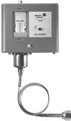 Pressure Controls
| Product | # | Range | Differential | Switch | Capillary | Connection | Cover | Notes |
| ALCO | FF115-S1 BAK | 24″/42 | 3/30 ADJ | SPDT | 36″ | w/ Flare | NEMA 1 | |
| ALCO | PS1-X1K 7/15 | 24″/42 | 3/30 ADJ | SPDT | 36″ | w/ Flare | NEMA 1 | |
| PENN | P70AB-12C | 12″/80 | 5/35 ADJ | Open LO | 36″ | w/ Flare | NEMA 1 | |
| ALCO | FF115-S3 BAK | 15″/100 | 7/70 ADJ | SPDT | 36″ | w/ Flare | NEMA 1 | |
| ALCO | PS1-X3K 50/65 | 15″/100 | 7/70 ADJ | SPDT | 36″ | w/ Flare | NEMA 1 | |
| PENN | P70AB-2C | 20″/100 | 7/50 ADJ | Open LO | 36″ | w/ Flare | NEMA 1 | |
| ALCO | FF115-S3 BAA | 15″/100 | 7/70 ADJ | SPDT | None | External Flare | NEMA 1 | |
| ALCO | PS1-X3A 50/65 | 15″/100 | 7/70 ADJ | SPDT | None | External Flare | NEMA 1 | |
| PENN | P170AB-2C | 20″/100 | 7/50 ADJ | Open LO | None | External Flare | NEMA 1 | |
| ALCO | FF115-S4 BAK | 15/290 | 15/145 ADJ | SPDT | 36″ | w/ Flare | NEMA 1 | |
| ALCO | PS1-X4K 115/145 | 15/290 | 15/145 ADJ | SPDT | 36″ | w/ Flare | NEMA 1 | |
| PENN | P70AA-2C | 0/150 | 12/40 ADJ | Open LO | 36″ | w/ Flare | NEMA 1 | |
| PENN | P70AA-3C | 100/300 | 25/75 ADJ | Open LO | 36″ | w/ Flare | NEMA 1 | |
| ALCO | FF115-S5 BAK | 90/450 | 30/220 | SPDT | 36″ | w/ Flare | NEMA 1 | |
| ALCO | PS1-X5K 230/290 | 90/450 | 30/220 | SPDT | 36″ | w/ Flare | NEMA 1 | |
| PENN | P70AA-118C | 100/400 | 35/200 | Open LO | 36″ | w/ Flare | NEMA 1 | |
| PENN | P70CA-3C | 50/450 | 60/150 | Open HI | 36″ | w/ Flare | NEMA 1 | |
| ALCO | FF115-S5 BAA | 90/450 | 30/220 | SPDT | None | External Flare | NEMA 1 | |
| ALCO | PS1-X5A 140/280 | 90/450 | 30/220 | SPDT | None | External Flare | NEMA 1 | |
| PENN | P170AA-118C | 100/400 | 35/200 | Open LO | None | External Flare | NEMA 1 | |
| PENN | P170CA-3C | 50/450 | 60/150 | Open HI | None | External Flare | NEMA 1 | |
| ALCO | FF115-S5 BRK | 90/450 | Manual | SPDT | 36″ | w/ Flare | NEMA 1 | |
| ALCO | PS1-Y5K 230/290 | 90/450 | Manual | SPDT | 36″ | w/ Flare | NEMA 1 | |
| PENN | P70DA-1C | 50/450 | Manual | Open HI | 36″ | w/ Flare | NEMA 1 | |
| PENN | P70KA-1C | 50/450 | Manual | M-Block | 36″ | w/ Flare | NEMA 1 | (3) |
| ALCO | FF115-S5 BRA | 90/450 | Manual | SPDT | None | External Flare | NEMA 1 | |
| ALCO | PS1-Y5A 330/390 | 90/450 | Manual | SPDT | None | External Flare | NEMA 1 | |
| PENN | P170DA-1C | 50/450 | Manual | Open HI | None | External Flare | NEMA 1 |
Notes:
-
- Main opens HI, auxilliary opens LO (primarily used for alarm circuit).
Cross-Reference
ALCO® Cross Reference (Continued)
![]()
![]()
![]()

![]() Dual Pressure Controls
Dual Pressure Controls
| Product | # | LO Side | Differential | HI Side | Differential | Capillary | Connection Notes |
| ALCO | FF215-S9 BAUK | 24″/42 | 3/30 | 90/450 | 60 FXD | 48″ | W/ Flare |
| ALCO | PS2-Y9K | 24″/42 | 3/30 | 90/450 | 60 FXD | 48″ | W/ Flare |
| PENN | P70SA-1C | 12″/80 | 5/35 | 100/500 | 60 FXD | 36″ | W/ Flare |
| ALCO | FF215-S7 BAUK | 15″/100 | 7/70 | 90/450 | 60 FXD | 48″ | W/ Flare |
| ALCO | PS2-Y7K | 15″/100 | 7/70 | 90/450 | 60 FXD | 48″ | W/ Flare |
| PENN | P70SA-1C | 12″/80 | 5/35 | 100/500 | 60 FXD | 36″ | W/ Flare |
| ALCO | FF215-S7 BAUA | 15″/100 | 7/70 | 90/450 | 60 FXD | None | External Flare |
| ALCO | PS2-Y7A | 15″/100 | 7/70 | 90/450 | 60 FXD | None | External Flare |
| PENN | P170SA-1C | 12″/80 | 5/35 | 100/500 | 60 FXD | None | External Flare |
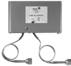 Lube Oil Pressure Controls
| Product | # | Range | Reset | Delay | Capillary | Connection | Cover | Notes |
| ALCO | FD113-ZUK | 4/65 ADJ | Manual | 20-150 secs. | 36″ | W/ Flare | NEMA 1 | |
| PENN | P28AA-**C | 8/70 ADJ | Manual | Note (4) | 36″ | W/ Flare | NEMA 1 | (4) |
| PENN | P45NCA-12C | 9.0 FXD | Manual | 120 secs. | 36″ | W/ Flare | NEMA 1 | (5) |
| PENN | P45NCA-82C | 6.5 FXD | Manual | 45 secs. | 36″ | W/ Flare | NEMA 1 | (5) |
| ALCO | FD113-ZU | 4/65 ADJ | Manual | 20-150 secs. | None | External Flare | NEMA 1 | |
| PENN | P128AA-**C | 8/70 ADJ | Manual | Note (4) | None | External Flare | NEMA 1 | (4) |
| PENN | P145NCA-12C | 9.0 FXD | Manual | 120 secs. | None | External Flare | NEMA 1 | (5) |
| PENN | P145NCA-82C | 6.5 FXD | Manual | 45 secs. | None | External Flare | NEMA 1 | (5) |
Notes:
-
- Choose correct control below based on timing required and desired pressure connection:
| P28AA-1 | 8/70# | 90 Secs. | 36″ | W/ Flare |
| P28AA-2 | 8/70# | 60 Secs. | 36″ | W/ Flare |
| P28AA-17 | 8/70# | 120 Secs. | 36″ | W/ Flare |
| P28AA-18 | 8/70# | 45 Secs. | 36″ | W/ Flare |
| P128AA-1 | 8/70# | 90 Secs. | None | External Flare |
| P128AA-2 | 8/70# | 60 Secs. | None | External Flare |
| P128AA-17 | 8/70# | 120 Secs. | None | External Flare |
-
- Verify timing specifications.
![]()
![]()
![]()
![]()
NOTES
![]()
![]()
![]()
![]()
NOTES
![]()
![]()
![]()
![]()
NOTES
![]()
![]()
![]()
![]()
NOTES
Johnson Controls offers a broad line of innovative, high performing and energy-saving HVAC and refrigeration controls

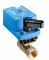
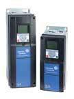
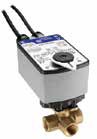
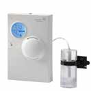
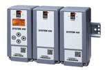
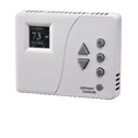
![]()
![]()
![]()
![]()
![]()
![]()
![]()
![]()
![]()
![]()
REFRIGERATION CONTROLS
VARIABLE SPEED DRIVES
VALVES
ACTUATORS
SENSORS & THERMOSTATS
HVAC CONTROL PANEL PRODUCTS
DAMPERS, LOUVERS & AIR MEASURING PRODUCTS
PNEUMATICS
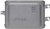

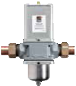 We are in the business of building efficiency. We create buildings
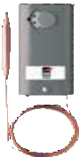 and environments that help people achieve and enterprises succeed. We do that by delivering energy savings. Operational savings. And sustainable solutions. In fact,
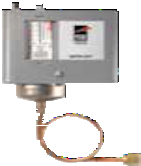 PENN commercial refrigeration controls by Johnson Controls have been serving the cooling needs of millions of customers worldwide for more than 95 years.
For more information, or to purchase Johnson Controls products, call 1-800-275-5676 or 1-800-482-2778.
Johnson Controls, the Johnson Controls logo and the PENN by Johnson Controls logo are registered trademarks of Johnson Controls, Inc. in the United States of America and other countries. Other trademarks used herein may be trademarks or registered trademarks of other companies.
![]()
![]()
![]()
![]()
![]()
© 2015 Johnson Controls, Inc. P.O. Box 423, Milwaukee, WI 53201 Printed in USA PUBL-5510 (Rev. 10/15) www.johnsoncontrols.com