


In many cases, we need to decide whether a component is faulty, or just wrongly installed. There are also situations where we need to decide exactly which component should be replaced. We are using the multimeter (multitester) for checking the continuity of wires, measuring the resistance values of heaters and thermistors, and measuring the voltage coming from the PSU and going to the heaters.
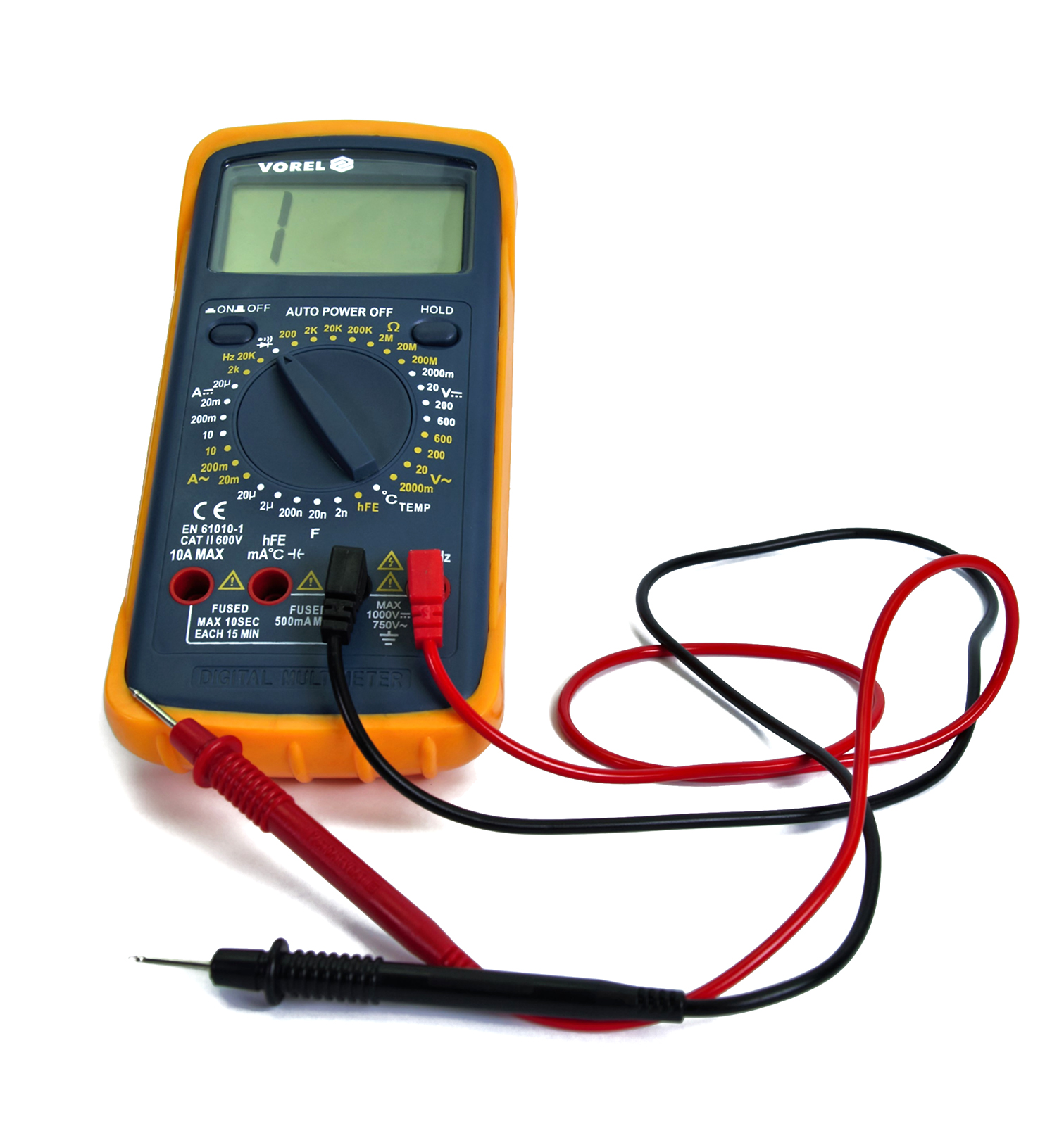
If you don’t have a multimeter, you can consider one that is similar to what is depicted above. The device does not have to be expensive. 10-15 USD/EUR will get you something that does the job just fine.
How to measure
To get started, we first have to properly connect the two measurement probe cables to the multimeter.
- The black lead goes into the COM port.
- The red lead goes into the port for Volts (V), Ohms (Ω), and Frequency (Hz).
Then we have to set the correct voltage or resistance range on the multimeter, depending on which component you are testing. For example, you can not measure 100K Ohm (Kilo=1000) if your meter is set to only 200 Ohm. You must set ut to 200K.
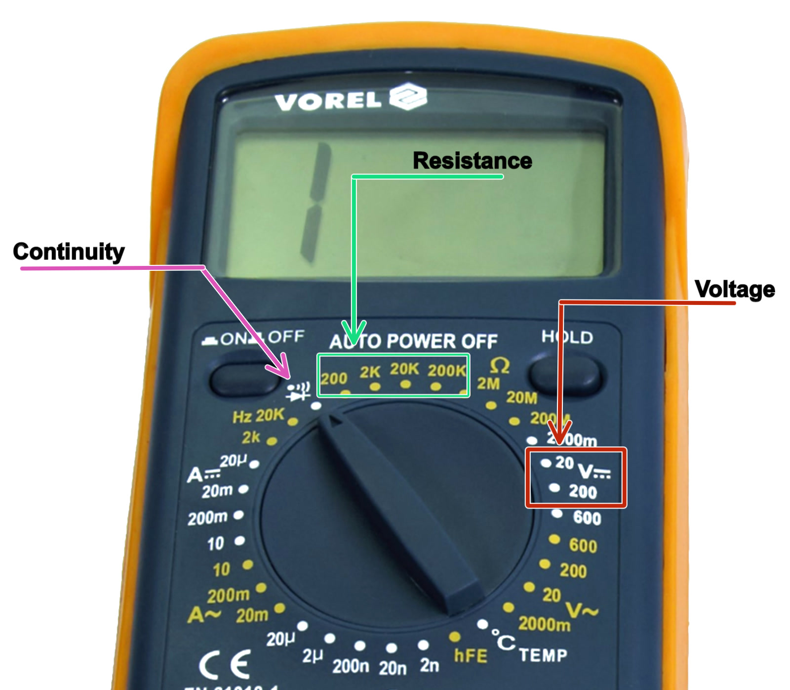
Reference for multimeter settings
Resistance setting:
- For all thermistors, set the resistance value to “200K” Ohm (green arrow), since the thermistor should have around 100K.
- For all heaters, set the resistance value to “200” Ohm (green arrow), since heaters read between 1 and 20 Ohm.
Voltage setting:
If measuring the voltage going to a heater or to the printer itself it is important to remember that the MK2/S and MK2.5S are 12V systems, while the MK3S is a 24V system.
- For a 12V system, set the meter to “20” volt (red arrow).
- For a 24V system, set the meter to “200” volt (red arrow).
Continuity setting:
The setting is indicated by the purple arrow and will display 0 and give a beep if the two probes connect, either by touching or connected by a cable. This is to test if a wire is broken or not.
Where to measure
For every component, there are several options, our main focus will be on the connectors. The measurement appears on the multimeter LCD as soon as the measurement probes touch the component. To obtain the correct and relevant values, this is where you need to apply the probes:
| Thermistors: metal inserts in plastic connectors | Hot end/Heat bed heater: screws holding the cables in the connector |
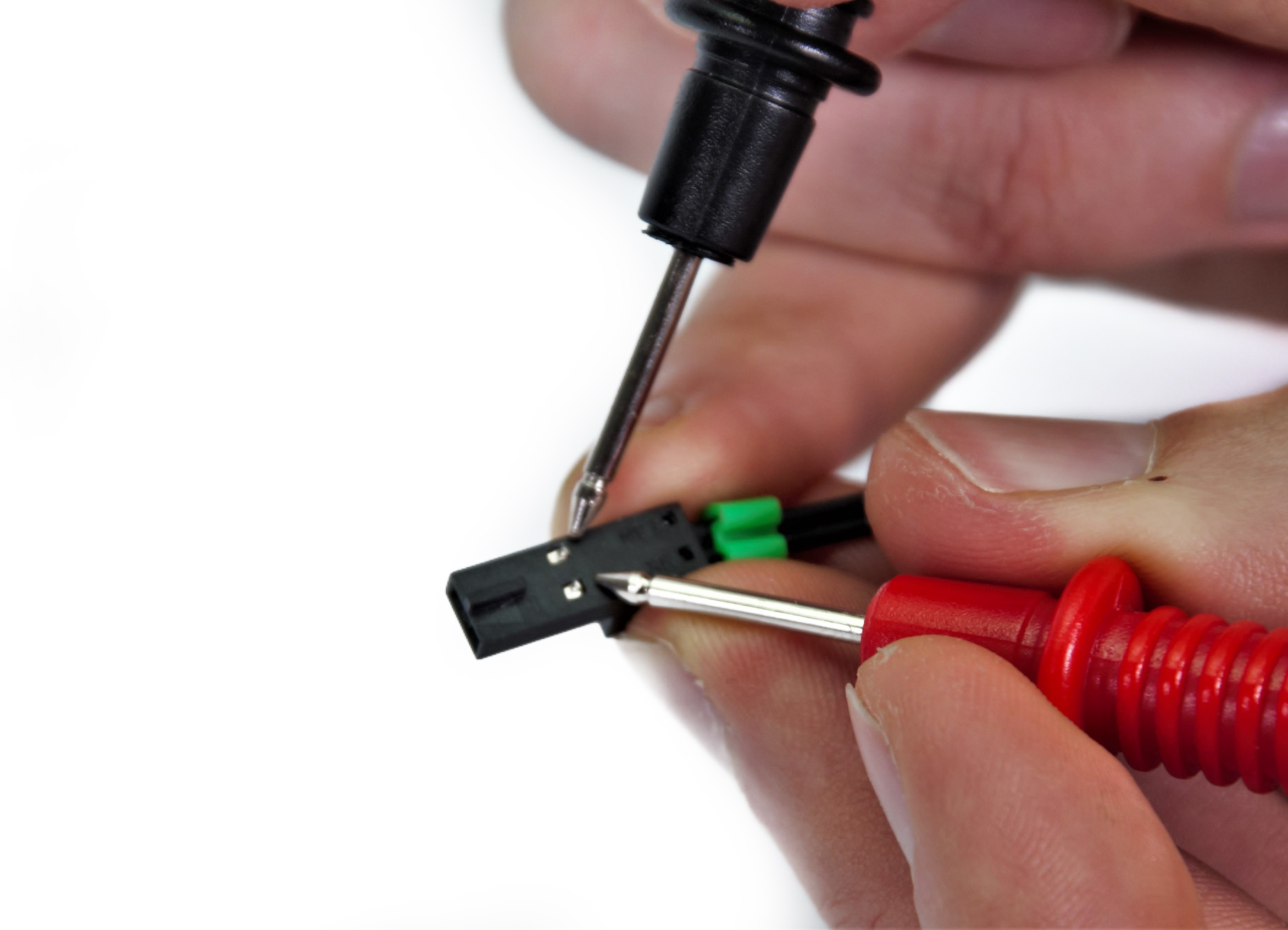 |  |
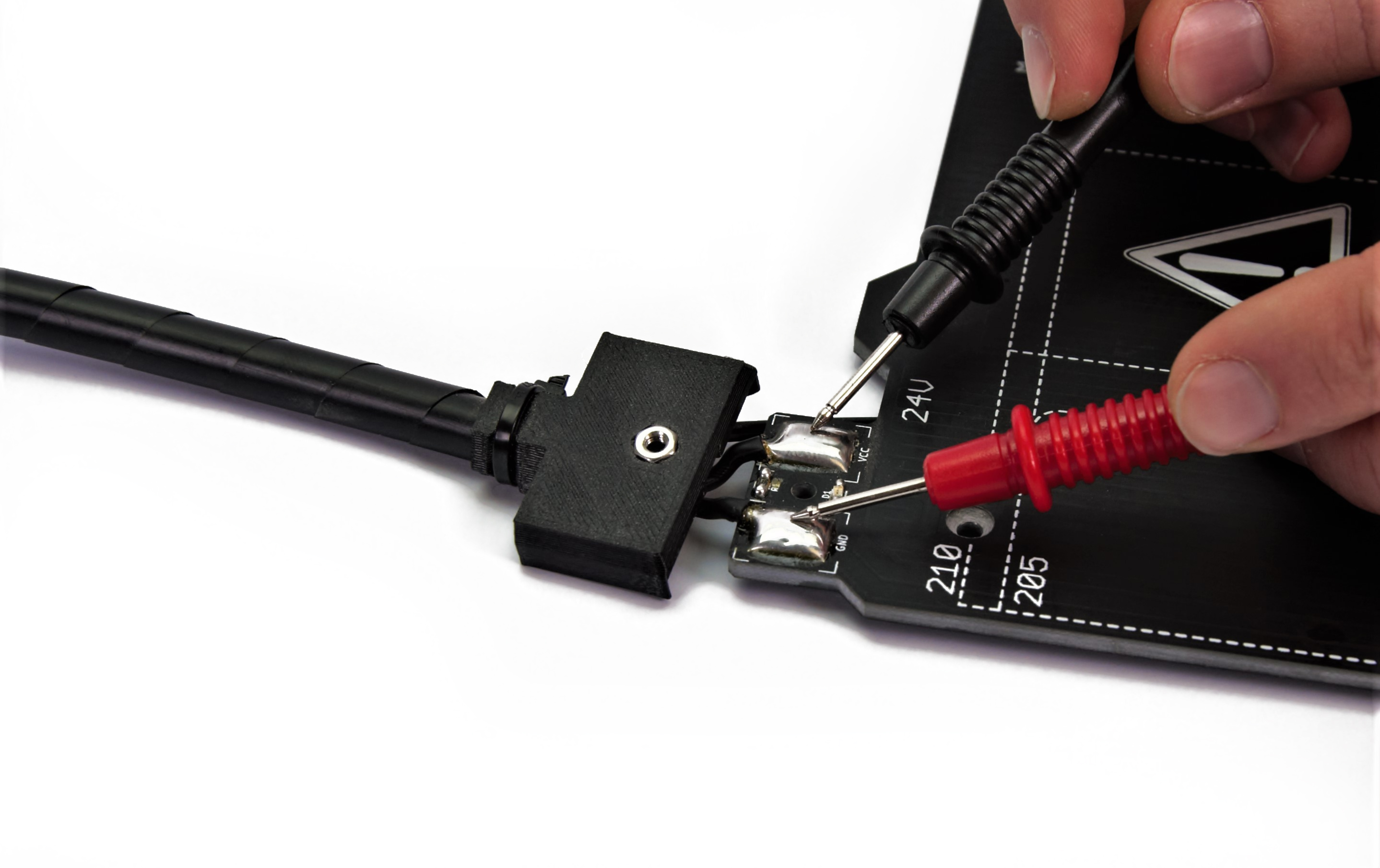
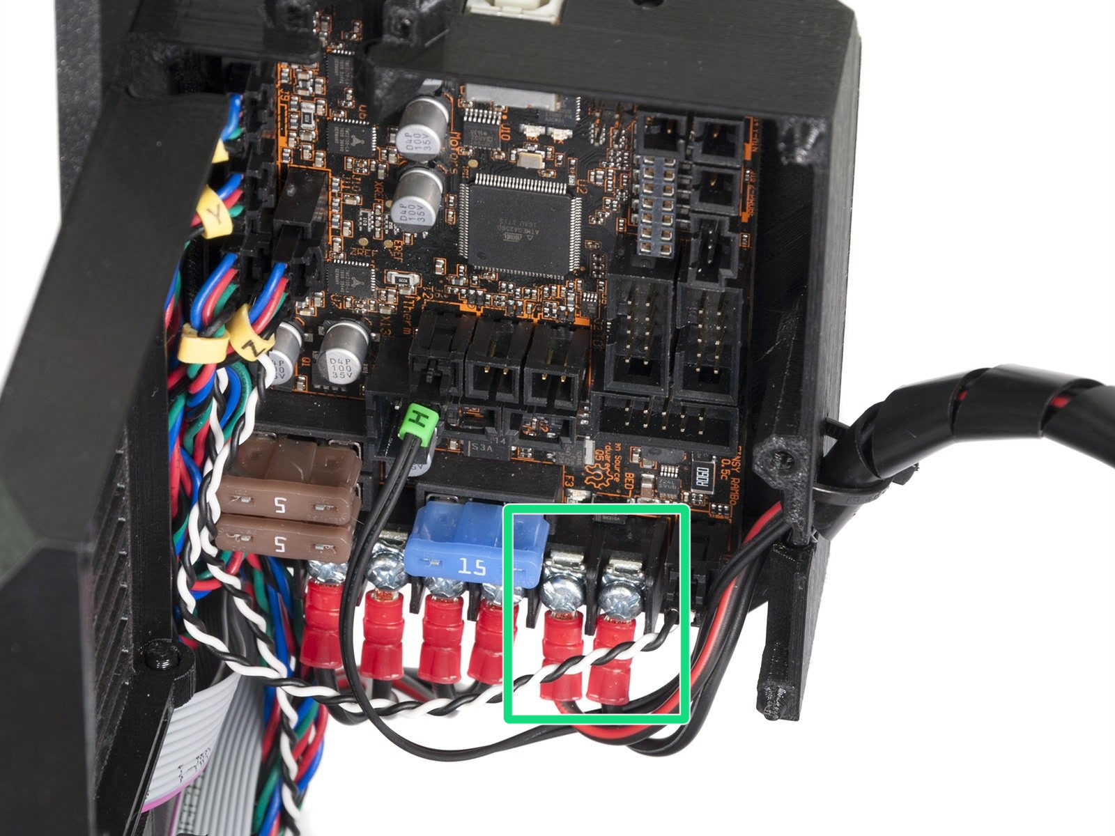
- Heat bed: the solder pads/screws holding the wires on the heat bed or the ends connected to the mainboard (green square). You must remove the cables from the board before you do the measurement! On MK2S/MK2.5S you can measure voltage and resistance on the screws holding the cables in the connector. Remove the connector from the board before measuring.
Fuses or wires
Fuses can be checked by using the continuity feature on a multimeter. The only thing that will be checked is whether the component is able to conduct signals or power. By touching each of the measurement leads of the multimeter to the other end of the fuse or wire, a signal (beep or 0 value on the multimeter screen) will indicate that the component is intact and therefore, should work.
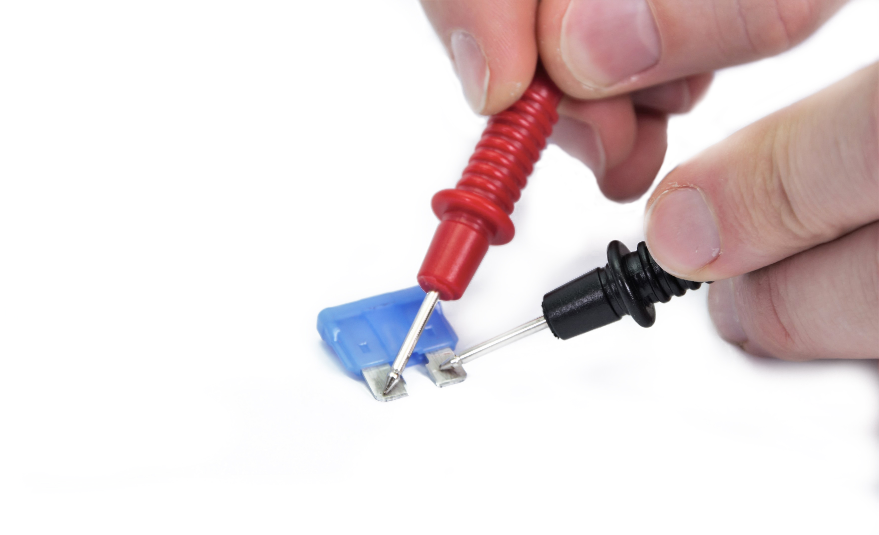
The fuse for the PSU can be taken out of the slot above the power cord by using a flat head screwdriver.

Resistance
For this measurement, the printer has to be turned off, at room temperature and the component that is measured has to be unplugged from the RAMBO!
In order to check if heaters are within their range of specified resistance, the following measurements can be done. For this measurement, the multimeter needs to be set to the lowest range which includes 20Ω.
The measurement can be done on the screws in the connector for both the hot end heater and the heat bed. For the heat bed, it is also possible to probe the solder pads/screws holding down the cables. Please see the pictures above.
Heaters
| MINI | Hot end heater | [12.3 Ω – 15.1 Ω] |
| Heat bed | [4.5 Ω – 6.5 Ω] | |
| MK3/S | Hot end heater | [12.3 Ω – 15.1Ω] |
| Heat bed | [2.0 Ω – 4.0 Ω] | |
| MK2/S | Hot end heater | [3.1 Ω – 3.8 Ω] |
| Heat bed | [0.9 Ω – 1.1 Ω] |
The measurement of the resistance of the hot end heater and the heatbed with a multimeter is only indicative and may vary from the actual resistance by tens of percent depending on the temperature. The measured values should therefore only be taken as a guide in identifying the problem.
Thermistors
For this measurement, the printer has to be turned off, at room temperature and the component that is measured has to be unplugged from the RAMBO!
In order to check if thermistors are within their range of specified resistance, the following measurements can be done. For this measurement, the multimeter needs to be set to the lowest range which includes 150 kΩ. It is common this is 200K on multimeters.
All thermistors are rated to be 100 kΩ at 25 °C. To be realistic, with a varying temperature between 20°C and 30°C, you can expect [80 kΩ – 125 kΩ].
Always check both thermistors to compare the two. Are they different, one is probably faulty.
Voltage
For this measurement, the printer will be turned on and there will be a risk of shorting the circuit. Always make sure to keep + and – from touching each other!
In order to check if the correct voltage is being supplied to the heaters, the following measurements can be done. For this measurement, the multimeter needs to be set to the lowest range which includes 24V.
The measurement can be done on the screws in the connector for both the hot end heater and the heat bed. For the heat bed, it is also possible to probe the solder pads/screws holding down the cables. In this case, the connectors have to be connected to the RAMBO.
To measure, start preheating the printer to PLA and measure the component you are investigating.
The following values can be expected:
| MINI | Hot end heater | [23V – 24.5V] |
| Heat bed | [23V – 24.5V] | |
| MK3/S | Hot end heater | [23V – 24.5V] |
| Heat bed | [23V – 24.5V] | |
| MK2/S | Hot end heater | [11V – 13.5V] |
| Heat bed | [11V – 13.5V] |
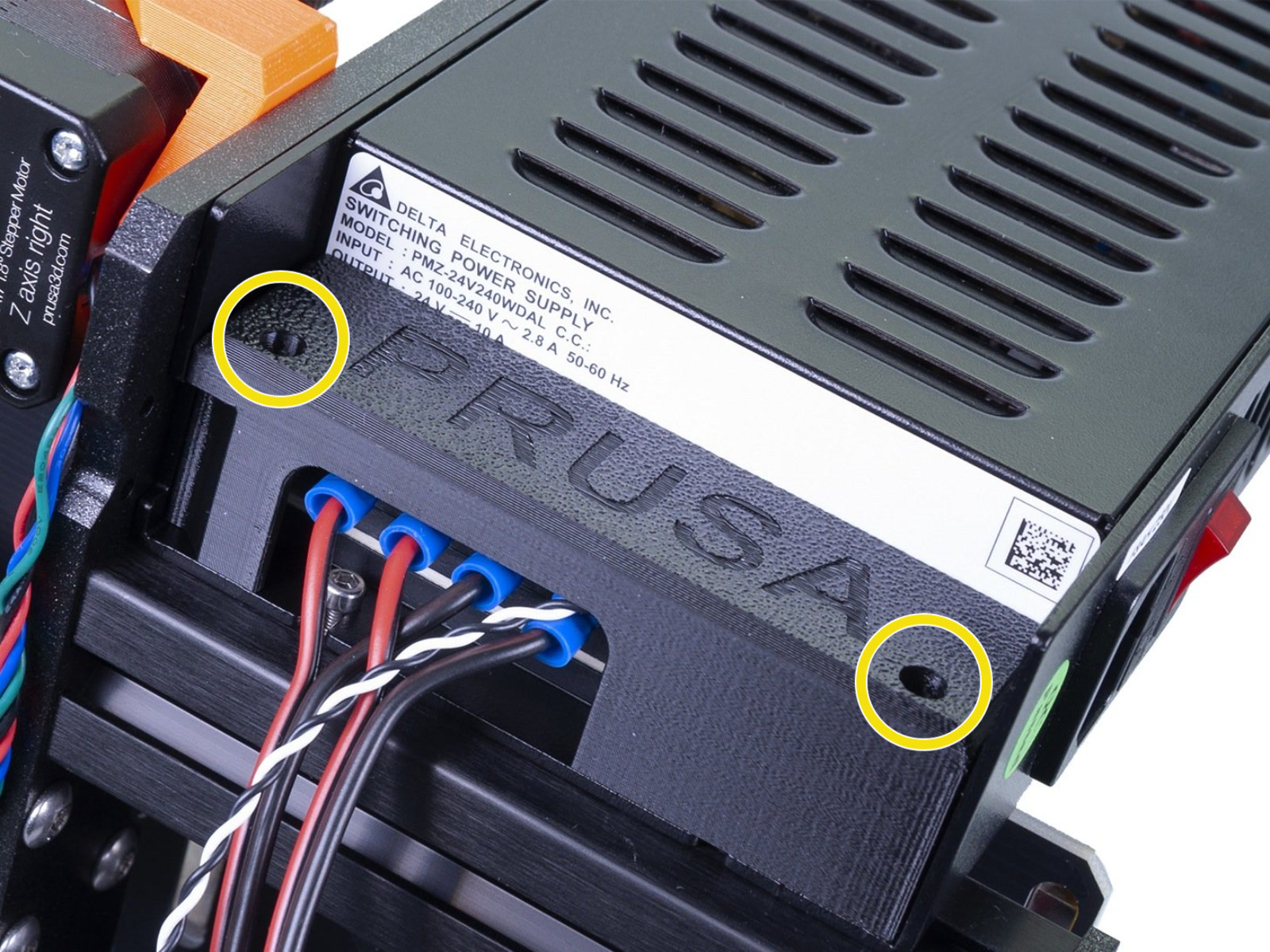
If you suspect the PSU is dead, and you have checked the external fuse, you can probe the terminals directly. Remove the two screws holding the cover (yellow circles) and you will have access to the power terminals.
Be very careful when probing the contacts. Make sure you do not short-circuit any terminals.
VCC and ground (+ and -) are divided into two pairs, where the two left connectors are VCC (red arrows) and the two right connectors are ground (blue arrows). Measure one from each pair.
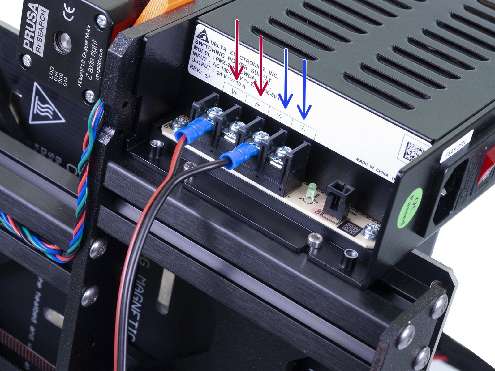
Measuring the DC output on brick PSUs, like supplied with the Original Prusa MINI, is not recommended. You can easily create a short circuit and damage yourself or the component.