


Earlier this week I had three pieces of metering equipment land on the bench at the same time: a split-core current transformer, a 480-volt revenue submeter, and a kWh demand meter older than my truck. The handwritten note on top of the box said “wrap the CT through the meter input 15 times to make it work.” That instruction was wrong — not partially wrong, completely wrong — and explaining why it’s wrong turned out to be a useful primer on how current transformers actually work. So here’s the writeup.
If you’re an electrician who installs submeters, or a building owner trying to figure out why your shiny new energy meter reads zero, this is for you.
The cast of characters
Three pieces of equipment, all related to the same metering project:
- Magnelab SCT-2000-1000 — a 1000-amp split-core current transformer with a 2-inch window. UL listed, Class 1 accuracy. Already on hand.
- Leviton VerifEye Series 2000, model 2N480-041 — a 3-phase kWh submeter rated for 277/480 V WYE service at up to 400 A. Brand new in the box.
- National Meter Industries Series 7000, KD 7834 — a classic “Watt Watcher” demand meter, also 277/480 V, 3-phase 4-wire. Older but rebuildable.
The goal was simple: install both submeters on a 400-amp service, using the Magnelab CT to feed the Leviton meter and source different CTs for the NMI. Then the note appeared suggesting we could “adjust” the Magnelab to a 100:0.01 output by wrapping the primary 15 times through the window. That note conflated two completely different concepts. Let me unpack why.
Three CTs, three signal standards, zero interchangeability
Current transformers come in three common output formats, each developed for a different era of metering hardware. They look similar from the outside — donut, window, two wires — but the signal they produce is fundamentally different.
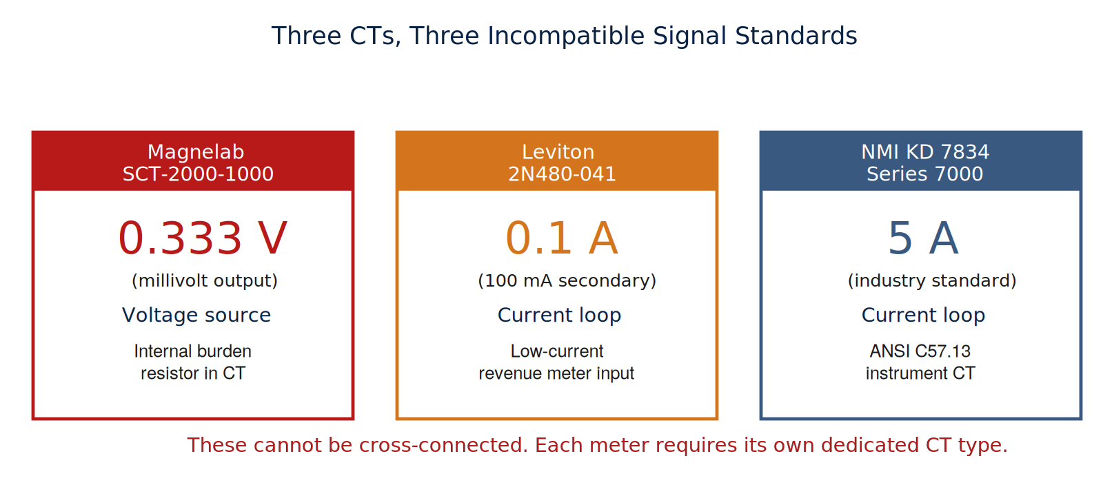
1. 0.333 V (millivolt) output
This is what the Magnelab produces. Inside the CT housing is an internal burden resistor that converts the secondary current to a voltage signal. The output looks, electrically, like a low-voltage AC voltage source — nominally 333 millivolts AC when the primary is carrying full rated current.
The advantage: open-circuiting the secondary is harmless. The internal burden takes the brunt of the current, so the open-circuit voltage stays bounded. You can pop the leads off a millivolt CT under load and nothing bad happens. This is why they dominate the building-automation and BMS sub-metering space.
The disadvantage: only meters specifically designed for millivolt input will read them. The meter expects a Thévenin-equivalent voltage source feeding into a high-impedance input. That’s a fundamentally different front-end design than the current-loop standards.
2. 0.1 A (100 mA secondary)
This is what the Leviton VerifEye Series 2000 requires. It’s a current-loop signal — the CT is a current source, the meter is a current sink — but at much lower magnitude than the classic 5 amp standard. Modern revenue-grade submeters use this format because it lets you run long secondary wire runs without significant burden loss, while still giving you the noise immunity of a current loop.
The meter input impedance is typically a few ohms. A voltage source — like a 0.333 V Magnelab — cannot drive this input correctly. The meter expects to draw current, not to see a voltage. Even if the polarities miraculously aligned, the resulting reading would be garbage.
3. 5 A secondary
The classic ANSI C57.13 instrument transformer standard, still used by the bulk of utility-grade revenue meters — including the NMI KD 7834. These CTs have no internal burden; the meter or shorting block provides the burden through its current-summing input shunt.
Two important consequences:
- A 0.333 V source feeding this input produces no measurable signal, because the meter input impedance is essentially zero (it’s a shunt). The “voltage” gets dropped across the source impedance of the Magnelab, and the meter sees nothing.
- Open-circuiting the secondary while the primary is energized is dangerous. More on that in the safety section below.
Mixing CT signal standards is not a matter of “reading the wrong scale” or “needing to convert units.” The meter’s front-end circuitry is fundamentally different for each type. A voltage-mode source feeding a current-mode input reads zero, reads a garbled non-linear value, or damages the input stage. The output type of the CT must match the input type of the meter. Period.
Why “just wrap it 15 times” doesn’t fix it
There is a legitimate, well-known field technique for adapting a CT: pass the primary conductor through the window N times to multiply the effective primary turns. This changes the CT’s effective primary current rating — useful when the CT is rated for far higher current than what’s actually flowing, to improve resolution on a smaller load.
The math is simple. A 1500 A : 0.333 V CT wrapped with 15 primary turns becomes a 100 A : 0.333 V CT (1500 ÷ 15 = 100). A 1000 A : 0.333 V CT wrapped 10 times becomes a 100 A : 0.333 V CT. The trick works.
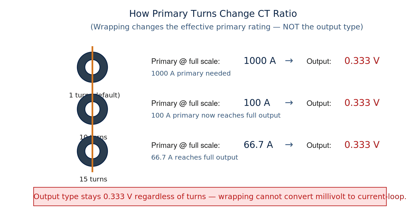
What wrapping cannot change is the secondary output standard. The Magnelab has an internal burden resistor that fixes its output at 0.333 V. No amount of turns ratio manipulation will make it produce 0.1 A or 5 A into a current-loop input.
The output type is built into the CT’s internal construction: the presence or absence of an internal burden resistor, the secondary winding turn count, the secondary insulation rating. External primary turns operate on the magnetic flux in the core. They don’t alter the secondary circuit topology.
The phrase “adjust to a 100:0.01 output” appears to combine two distinct concepts: primary-turn scaling and secondary output standard. “100 : 0.01” isn’t a standard meter input on either the Leviton (needs 0.1 A) or the NMI (needs 5 A). Even if it were achievable through turns, neither meter would read it.
The right answer: source the correct CTs
There’s no clever workaround here. The fix is to buy CTs that match each meter’s native input.
For the Leviton 2N480-041 (needs 400 : 0.1 A)
Three split-core CTs with 0.1 A secondary output. Options:
| Manufacturer | Part number | Type | Accuracy | Notes |
|---|---|---|---|---|
| Leviton | CTS04-SCS | Split-core, 400:0.1 A | 1.0% | OEM match |
| Leviton | CTH04-SCS | Solid-core, 400:0.1 A | 0.5% | Revenue-grade |
| Continental Control Systems | ACT-0750-401 | Split-core, 400:0.1 A | 1.0% | Cross-compatible |
Verify current Leviton catalog numbers before ordering — they periodically change the suffix scheme. Whatever you buy, confirm “0.1 A secondary” on the datasheet. That’s the critical spec.
For the NMI KD 7834 (needs 400 : 5 A)
Three split-core CTs with 5 A secondary. My recommendation:
| Manufacturer | Part number | Window | Accuracy | Approx cost (each) |
|---|---|---|---|---|
| Eaton (recommended) | CT-SP-5-400-5A | 2.0″ × 3.5″ | 0.6% | $110–$250 |
| Eaton (alternative) | CT-SP-4-400-5A | 1.30″ × 1.70″ | 0.5% | $250–$320 |
| Flex-Core | FCR400/5-R | Round split | 0.3% (relay) | $200–$300 |
| Byram Labs | BL-5-400-RA005 | 2.0″ × 3.5″ | 0.5% | $150–$225 |
The Eaton CT-SP-5-400-5A wins on price-availability-window-size balance through major U.S. distributors. The bigger window (2.0″ × 3.5″) matters because most 400 A feeders are already terminated with lugs by the time you’re installing CTs, and a small-window CT won’t clear the lug.
What to do with the Magnelab
The Magnelab SCT-2000-1000 isn’t bad — it’s just not compatible with either of these meters. Save it for a millivolt-input project. Common compatible meters include:
- Continental Control Systems WattNode (Pulse or Modbus)
- Veris Industries H8035 / H8036 / E50 series
- Accuenergy AcuRev 1000 / 2000 / Acuvim
- eGauge Systems EG4xxx
- Onset HOBO Energy Logger Pro / U30
- DENT Instruments PowerScout, ELITEpro XC
- Siemens 9100 Power Meter series
Any of these accept the 0.333 V output directly. The Magnelab is well-suited to a future BMS or sub-metering project — particularly anywhere a fully safe (open-circuit-tolerant) CT is needed.
CT polarity — the part everybody gets wrong at least once
Every CT has an explicit polarity. The label, an arrow, a dot, or an “H1” marking indicates the line side. That side must face the source — the utility, transformer, or line side of the system. Get it backward and the meter sees that phase as flowing in reverse and subtracts it from the total.
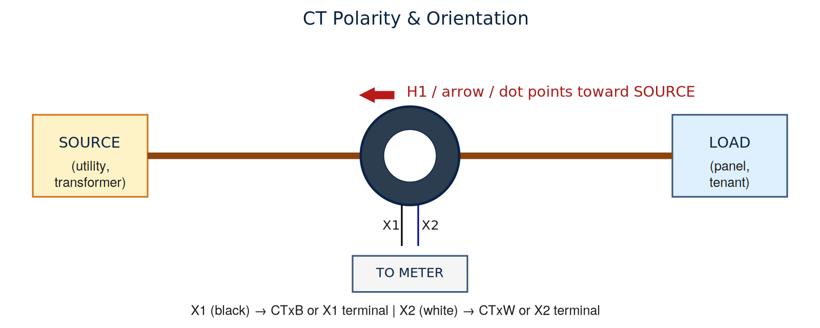
The Leviton has a red “Reverse Phase” LED that illuminates if any CT is reversed — great diagnostic. The older NMI doesn’t have that, so verify with a clamp-on amp meter after energization. If a phase reads half the expected value, or reads negative, you’ve got a backward CT.
Installing the NMI KD 7834
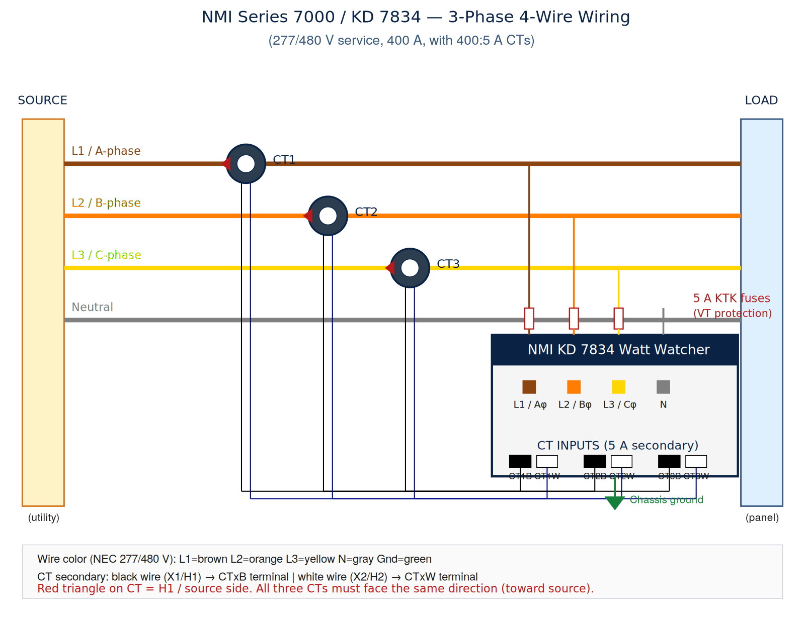
Assuming three Eaton CT-SP-5-400-5A CTs on a 277/480 V 3-phase 4-wire WYE service rated 400 A.
Work on a 277/480 V service requires arc-flash PPE rated to the incident energy of the source. Perform an arc-flash hazard analysis per NFPA 70E before opening any energized panel. De-energize and lockout/tagout per OSHA 29 CFR 1910.147 before installing CTs around live conductors unless absolutely necessary.
Pre-install checklist
- Verify panel service matches meter rating: 277/480 V, 3-phase, 4-wire WYE.
- Confirm utility-side service ampacity is at least 400 A and the CTs are correctly sized.
- Plan meter mounting location within 6 ft of the CTs (Eaton factory lead length).
- Identify a 15 A 3-pole breaker space (or fused disconnect) for the meter’s voltage reference / power supply.
- Arc-flash hazard analysis completed; appropriate PPE on hand.
- Lockout/tagout devices and absence-of-voltage tester ready.
- Shorting block or short jumper wires available for CT secondaries (critical for future service work — see safety section).
- Permit pulled if required by your local jurisdiction.
Wiring procedure
- Mount the meter to its enclosure surface using the four corner mounting screws.
- Run conduit between the meter location and the panel where the CTs will be installed. CT secondary wires can share conduit with the meter voltage reference wires, but should not share conduit with high-current power conductors when avoidable.
- Install all three CTs at the same location in the panel — typically downstream of the main lugs, on each phase conductor (A, B, C). The neutral does not require a CT for a balanced 3-element meter.
- Verify all three CTs are oriented the same way: H1 / arrow / source-side label all facing toward the utility.
- Snap each CT closed around its phase conductor. Confirm the latches are fully engaged. A partially-closed CT has a large air gap in its magnetic circuit and reads low.
- Connect the CT secondaries. From each CT, the black wire is X1 (polarity side); the white wire is X2. Connect Phase A CT to CT1B / CT1W on the meter; Phase B to CT2B / CT2W; Phase C to CT3B / CT3W.
- Land Phase A on the meter terminal labeled L1 / Aφ; Phase B on L2 / Bφ; Phase C on L3 / Cφ; Neutral on N.
- Protect each voltage tap with a fast-acting fuse (5 A KTK or equivalent) close to the source. The KD 7834 does not have internal fuses on the voltage reference inputs.
- Connect the green chassis-ground wire to the panel ground bus.
- Per NEC, CTs may not occupy more than 75% of the wiring space of any cross-sectional area inside the panel. Verify before final close-up.
Energize and verify
- Close the CT shorting block to the “normal” (non-shorting) position if one is used.
- Restore voltage to the panel and remove lockout devices.
- Press the yellow PUSH SEQUENCE button on the meter front to step through the display: Current kWh, Current Demand, Max Demand, Max Demand Time, Accumulated Demand, Present Time.
- Phase A / B / C indicator LEDs should be lit when current flows on the corresponding phase.
- Verify the current reading on each phase against a clamp-on amp meter. A reading at half the expected value, or negative, indicates a reversed CT — power down and swap X1 and X2 at that terminal pair.
- Set the demand reset key to lock the max demand register.
Installing the Leviton 2N480-041
Procedure follows the Leviton Series 2000 Quick Start Installation Guide (document PK-A3338-10-00-0A). Assuming three Leviton-compatible 400:0.1 A CTs.
The Leviton 0.1 A CTs do not carry the open-circuit voltage hazard of 5 A CTs. They’re safer to handle. But they still must be polarized correctly and paired with the right phase voltage reference to read properly.
Step-by-step (per Leviton QSG)
- Mount the meter. The Series 2000 is designed for permanent surface mounting. Mount near the load center.
- Install conduit. Pull voltage reference and CT secondary wires through. Wire sizes per NEC.
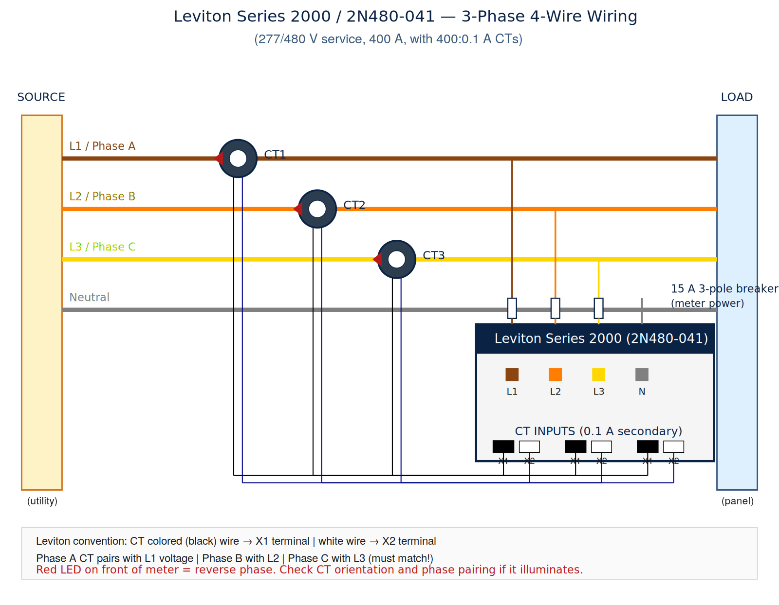
- Install CTs. H1 label or arrow must face the source. Wire each CT secondary to the meter:
- Phase A CT: colored (black) wire to X1, white wire to X2 at the CT1 input pair.
- Phase B CT: same convention at CT2.
- Phase C CT: same at CT3.
- Per the Leviton instructions: white wires always land on X2 terminals.
- Meter power & voltage references. Connect the meter to a 15 A 3-pole circuit breaker for both meter power and voltage reference. If no breaker space is available, voltage can be sourced by tapping off main lugs (per NEC and local code) using fast-acting fuses 0.5–2 A:
- Line 1 → L1 terminal (meter power and Phase A voltage reference)
- Line 2 → L2 terminal (Phase B voltage reference)
- Line 3 → L3 terminal (Phase C voltage reference)
- Neutral → N terminal
Verify phase alignment
Phase A CT pairs with Line 1 voltage. Phase B with Line 2. Phase C with Line 3. If the red LED Reverse Phase Indicator illuminates after energization, the install is incorrect. Per Leviton, check three things: (1) CT line/load orientation, (2) voltage reference connections match the CT phase placement, (3) polarity at the CT input terminals.
The two green LEDs are pulse-output duty cycle indicators — left LED is 1000 Wh duty cycle (500 Wh on / 500 Wh off); right LED is 10 Wh duty cycle (5 Wh on / 5 Wh off).
Optional: isolated pulse output
The Series 2000 has an isolated pulse output channel — terminals labeled 10, 1K, COM. The “10” terminal pulses every 10 Wh; “1K” pulses every 1000 Wh; COM is the common return. These outputs feed a BMS, Modbus gateway, or pulse-counting data logger.
The thing nobody warns you about: open-circuit hazard on 5 A CTs
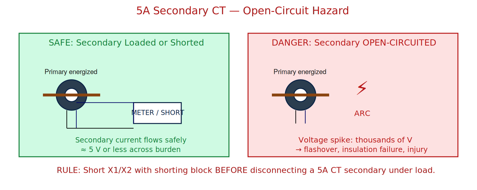
This applies to the Eaton CT-SP-5-400-5A and any other 5 A secondary CT — not to the Magnelab (millivolt) or Leviton (0.1 A) types. It’s the single most important thing to know about traditional revenue-grade CTs, and it’s the most common cause of CT-related accidents in the field.
The physics: a CT acts as a current source. With the primary energized, the secondary delivers a proportional current. If the secondary path is interrupted — you disconnect the meter, or a wire breaks, or a terminal gets loose — the CT tries to drive its rated current into infinite impedance.
The secondary voltage rises until either (a) something arcs over, (b) the insulation fails catastrophically, or (c) the core saturates. Voltages of several kilovolts are typical on a loaded 5 A CT that’s been opened. Several. Kilovolts.
How to service 5 A CTs safely
- Install a CT shorting block (also called a “test switch”) in the secondary wiring during original install. This lets you remove the meter for service without de-energizing the primary. They’re cheap and they’re life insurance.
- Before opening any 5 A CT secondary, place the shorting block in the “short” position so X1 and X2 are jumpered together. Verify with a continuity tester.
- If no shorting block is installed: de-energize the primary first, then verify zero current with a clamp meter before opening the secondary.
- If de-energizing isn’t possible (rare), short the secondary with a heavy gauge wire jumper (10 AWG minimum) before disconnecting from the meter.
- Never operate a 5 A CT with the secondary leads cut, dangling, or terminated in anything other than a meter, a shorting block, or another known low-impedance load.
The 0.333 V Magnelab and 0.1 A Leviton CTs do not share this hazard. They can be open-circuited safely. The hazard is specific to 5 A current-loop CTs. Know which type you’re working with.
What it cost
For the curious, here’s the budget for a complete pair of meter installs (CTs only — meters were already purchased):
| Item | Qty | Unit cost | Total |
|---|---|---|---|
| Eaton CT-SP-5-400-5A (for NMI) | 3 | ~$140 | ~$420 |
| Leviton CTS04-SCS (for Leviton meter) | 3 | ~$95 | ~$285 |
| CT shorting block (NMI install) | 1 | $45 | $45 |
| 5 A KTK fuses (NMI voltage refs) | 3 | $8 | $24 |
| 15 A 3-pole breaker (Leviton power) | 1 | varies by panel | $60–$200 |
| Estimated total | ~$830–$975 |
Distributors that consistently stock the Eaton CT-SP series in the U.S.: Graybar, Cooper Electric Supply, Rexel, CED, Warshauer Electric Supply, McNaughton-McKay, Revere Electric Supply. Call ahead — they’re stocked items but not always on the shelf. Lead time when ordered is typically 2–5 business days from Eaton’s Cleveland warehouse.
Takeaways
- CT signal standards are not interchangeable. 0.333 V, 0.1 A, and 5 A are three different worlds. Verify the spec before you buy.
- Primary turn wrapping scales the effective primary current rating, but it cannot convert a millivolt-output CT into a current-loop CT, or vice versa.
- CT polarity matters. The H1 / arrow / source side faces the source.
- 5 A CTs are dangerous to open-circuit under load. Install shorting blocks. Short before you open. Carry a clamp meter.
- Read the manufacturer’s quick-start guide before installing. Leviton’s PK-A3338 is two pages of dense gold.
And if you ever find a handwritten note suggesting you wrap a CT 15 times to make it work with the wrong meter — that’s a sign you’ve got the wrong CT for the job, not a sign you need to break out the lineman pliers.
References used in this writeup: Eaton Technical Data TD049001EN (5 A split-core CT family); Leviton document PK-A3338-10-00-0A (Series 2000 Quick Start); ANSI/IEEE C57.13 (instrument transformer requirements); ANSI C12.20 (electricity meter accuracy classes); NFPA 70 (National Electrical Code); NFPA 70E (electrical safety in the workplace); OSHA 29 CFR 1910.147 (lockout/tagout).